EP1597162B1 - Recipient pour matieres coulantes telles que des pates et des cremes - Google Patents
Recipient pour matieres coulantes telles que des pates et des cremes Download PDFInfo
- Publication number
- EP1597162B1 EP1597162B1 EP02788543A EP02788543A EP1597162B1 EP 1597162 B1 EP1597162 B1 EP 1597162B1 EP 02788543 A EP02788543 A EP 02788543A EP 02788543 A EP02788543 A EP 02788543A EP 1597162 B1 EP1597162 B1 EP 1597162B1
- Authority
- EP
- European Patent Office
- Prior art keywords
- section
- shape
- container according
- cross
- inlet
- Prior art date
- Legal status (The legal status is an assumption and is not a legal conclusion. Google has not performed a legal analysis and makes no representation as to the accuracy of the status listed.)
- Expired - Lifetime
Links
- 239000000126 substance Substances 0.000 title claims abstract description 16
- 239000006071 cream Substances 0.000 title claims description 41
- 239000012530 fluid Substances 0.000 title claims description 10
- 230000001788 irregular Effects 0.000 claims description 9
- 239000000463 material Substances 0.000 claims description 9
- 230000000694 effects Effects 0.000 claims description 3
- 239000013013 elastic material Substances 0.000 claims 1
- 238000007790 scraping Methods 0.000 claims 1
- -1 that is to say Substances 0.000 claims 1
- 239000006210 lotion Substances 0.000 abstract 1
- 239000006072 paste Substances 0.000 description 35
- 230000009969 flowable effect Effects 0.000 description 5
- 230000003796 beauty Effects 0.000 description 3
- 230000003247 decreasing effect Effects 0.000 description 3
- 210000003811 finger Anatomy 0.000 description 3
- 210000003813 thumb Anatomy 0.000 description 3
- 241000219198 Brassica Species 0.000 description 2
- 235000003351 Brassica cretica Nutrition 0.000 description 2
- 235000003343 Brassica rupestris Nutrition 0.000 description 2
- QKSKPIVNLNLAAV-UHFFFAOYSA-N bis(2-chloroethyl) sulfide Chemical compound ClCCSCCCl QKSKPIVNLNLAAV-UHFFFAOYSA-N 0.000 description 2
- 238000004140 cleaning Methods 0.000 description 2
- 229940079593 drug Drugs 0.000 description 2
- 239000003814 drug Substances 0.000 description 2
- 239000003925 fat Substances 0.000 description 2
- 239000000499 gel Substances 0.000 description 2
- 235000010746 mayonnaise Nutrition 0.000 description 2
- 239000008268 mayonnaise Substances 0.000 description 2
- 235000010460 mustard Nutrition 0.000 description 2
- 239000002674 ointment Substances 0.000 description 2
- 229940034610 toothpaste Drugs 0.000 description 2
- 239000000606 toothpaste Substances 0.000 description 2
- 208000031872 Body Remains Diseases 0.000 description 1
- 238000013459 approach Methods 0.000 description 1
- 230000001174 ascending effect Effects 0.000 description 1
- 230000015572 biosynthetic process Effects 0.000 description 1
- 239000004744 fabric Substances 0.000 description 1
- 239000002699 waste material Substances 0.000 description 1
Images




Classifications
-
- B—PERFORMING OPERATIONS; TRANSPORTING
- B65—CONVEYING; PACKING; STORING; HANDLING THIN OR FILAMENTARY MATERIAL
- B65D—CONTAINERS FOR STORAGE OR TRANSPORT OF ARTICLES OR MATERIALS, e.g. BAGS, BARRELS, BOTTLES, BOXES, CANS, CARTONS, CRATES, DRUMS, JARS, TANKS, HOPPERS, FORWARDING CONTAINERS; ACCESSORIES, CLOSURES, OR FITTINGS THEREFOR; PACKAGING ELEMENTS; PACKAGES
- B65D35/00—Pliable tubular containers adapted to be permanently or temporarily deformed to expel contents, e.g. collapsible tubes for toothpaste or other plastic or semi-liquid material; Holders therefor
- B65D35/24—Pliable tubular containers adapted to be permanently or temporarily deformed to expel contents, e.g. collapsible tubes for toothpaste or other plastic or semi-liquid material; Holders therefor with auxiliary devices
- B65D35/28—Pliable tubular containers adapted to be permanently or temporarily deformed to expel contents, e.g. collapsible tubes for toothpaste or other plastic or semi-liquid material; Holders therefor with auxiliary devices for expelling contents
- B65D35/30—Pistons
-
- B—PERFORMING OPERATIONS; TRANSPORTING
- B65—CONVEYING; PACKING; STORING; HANDLING THIN OR FILAMENTARY MATERIAL
- B65D—CONTAINERS FOR STORAGE OR TRANSPORT OF ARTICLES OR MATERIALS, e.g. BAGS, BARRELS, BOTTLES, BOXES, CANS, CARTONS, CRATES, DRUMS, JARS, TANKS, HOPPERS, FORWARDING CONTAINERS; ACCESSORIES, CLOSURES, OR FITTINGS THEREFOR; PACKAGING ELEMENTS; PACKAGES
- B65D2231/00—Means for facilitating the complete expelling of the contents
Definitions
- the invention relates to a container for flowable substances, such as pastes and creams, i. Substances which assume the formation of the container containing them, yet they have their own volume, according to the preamble of claim 1.
- tubes for toothpaste for beauty creams, for cleaning creams or for body care creams, as well as tubes for medicines and ointments.
- utensils such as mustard or mayonnaise, commercial pastes, gels and fat.
- this known type of container has the disadvantage that the escape of the paste or cream is very expensive, especially when a large proportion of the paste or cream has already leaked through previous use. In this case one must press carefully on the entire surface of the tube, starting from the lower end and then further up to the inlet and outlet channel, so that the residual paste or cream is conveyed into the, near the inlet and outlet channel near the region of the hollow body ,
- the proposed thrust member avoids, during its continuous rise along the hollow body, which dissipates the flowable material, it keeps him tight and promotes him continuously in the direction of the inlet and outlet channel, by preventing that in the subjacent part of the hollow body remains of the flowable Stoffes remain.
- this known container has the disadvantage that when ascending the thrust member can not be excluded that the last remnants of the paste or cream between the inner walls of the hollow body and the upper surface of the thrust member are included as soon as they are very close.
- the object of the present invention is the development of such a container, so that in a particularly simple and fast way, the escape of the flowable substance contained therein allows and at the same time its contents can be completely emptied. This object is achieved by a container having the features of claim 1.
- a container for flowable substances 2 such as pastes or creams, i.
- Fabrics which take the shape of the receiving container, yet they have their own volume.
- Such a container could be, for example, a tube for toothpaste, for beauty creams, for cleaning creams or for body care creams, as well as a tube for medicines and ointments. Also included are utensils such as mustard or mayonnaise, commercial pastes, gels and fat.
- the container comprises a deformable hollow body 1, in which the paste or cream 2 is located.
- the hollow body 1 is provided with an inlet and outlet channel 3, at the end of an inlet and outlet opening 4 is provided.
- the container further comprises a closure element 5.
- the closure element 5 is connectable to the inlet and outlet channel 3 in order to prevent the outward escape of the paste or cream 2 through the inlet and outlet openings 4.
- the container also comprises a thrust member 6, which is arranged in the hollow body 1, that the paste or cream 2 is located in the space between the inlet and outlet opening 4 and the thrust member 6. This is achieved by arranging the thrust member 6 at that end of the hollow body 1 opposite to the end having the inlet and outlet openings 4.
- the thrust member 6 is arranged without bonds in the hollow body 1 and is therefore able to slide under a Schubau fromein Quantum exert the fingers of a person on the hollow body 1.
- the paste or cream 2 is pushed by the thrust member 6 in the direction of the inlet and outlet opening 4 out.
- the thrust member 6 is constructed in several parts, an upper part 6a, a middle part 6b and a lower part 6c.
- the upper part 6 a is in contact with the uppermost paste or cream 2 and has a maximum cross-section equal to that of the hollow body 1. This upper part 6a ensures that the paste or cream 2 is pushed and conveyed.
- the middle part 6b has a uniform cross section on the same as that of the hollow body 1 is equal and on its surface a stripper clamp 7 is annularly arranged.
- This stripping clamp 7 is suitable, during the sliding of the thrust member 6, strip the inner surface of the hollow body 1 and prevents that during the sliding of the thrust member 6 in the underlying empty part of the hollow body 1, that part between the thrust member 6 and the lower ends of Container, remnants of paste or cream 2 left over.
- the lower part 6c is exposed to the thrust external action, which the thrust member 6 continuously from its initial position, that of the inlet and outlet channel 3 is opposite, to its end position, in the vicinity of the inlet and outlet channel 3, moves.
- the effect exerted by the user is more continuous when the lower part 6c is made of an elastically yielding material.
- a material may be provided which is elastically yielding in a natural way.
- small open channels 9 extend on the surface of the upper part 6a. In this way, it is precluded that remains of the paste or cream 2 are included when, in the end portion of the sliding of the thrust member 6, the surface of the upper part 6a and the inner walls of the hollow body 1 are very close.
- the presence of the channels 9 on the surface of the upper part 6a is therefore important, because in this case they allow the possibility of collecting the remains of the paste or cream 2 in the inlet and outlet channel 3, from where they are taken out in any case can be.
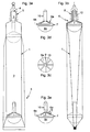
- the thrust member 6 In the first, arranged in the drawing sheet left and marked with the letter a longitudinal section, the thrust member 6 is shown in its initial position, while in the second, arranged in the drawing sheet right and marked with the letter b longitudinal section, the thrust member 6 in his End position shown. In this second longitudinal section, the thrust member 6 is indicated by dashed lines in its initial position.
- Thrust member 6 shown in dashed lines in another significant position, which is taken by him, during its intermittent sliding in the interior of the hollow body 1. It is a position that the thrust member 6, just before a suitably provided on its upper part 6a projection 10 penetrates into the inlet and outlet channel 3 occupies.
- This projection 10 penetrates in the end portion of the sliding of the thrust member 6 in the inlet and outlet channel 3 and serves to push any residue of the paste or cream 2 to the outside and to empty the inlet and outlet channel 3 completely.
- the last remnants of the paste or cream 2 accumulate in the inlet and outlet channel 3. They enter the inlet and outlet channel 3 by flowing into the small open channels 9, which also furrow the surface of the projection 10. The presence of these channels 9 prevents the projection 10 from clogging the inlet and outlet channel 3 completely and that the remains of the paste or cream 2 between the inner walls of the hollow body 1 and the surface of the upper part 6a of the thrust member 6 are included.
- the shape of the various parts 6a, 6b and 6c, which form the thrust member 6, also depends on the type of tube, in particular its cross section.
- the first example of a thrust member 6 according to the invention can be seen in particular in FIGS. 1c-1e.
- the upper part 6 a has the shape of a truncated cone with a round cross section and is provided with the projection 10.
- the middle part 6b has the shape of a cylinder with a round cross section and the Abstreifschelle 7, while the lower part 6c has an irregular shape.
- the irregular shape of the lower part 6c is that, as can be seen in particular in Figure 1c, which results from the fact that its lower part with an approximately elliptical, very squashed, almost rectangular cross-section on the upper part with round cross section connects.
- the second example of a thrust member 6 according to the invention can be seen in particular in FIGS. 2c-2e.
- the upper part 6a and the middle part 6b are the same as those of the above-mentioned first example.
- the lower part 6c is obtained by decreasing material to a lower part 6c, like that of the first example mentioned above, to form a shaped recess 8.
- This shaped recess 8 is intended to receive the thumb of the user's hand and facilitates the exercise of the external thrust action.
- the third example of a thrust member 6 according to the invention can be seen in particular in FIGS. 3c-3e.
- the upper part 6a has the shape of a truncated cone with a round cross section and is provided with the projection 10, while the central part 6b has the shape of a cylinder with a round cross section and the stripping clamp 7.
- the lower part 6c has the shape of a hemisphere, so that thanks to the symmetry of this part, the thrust external action exerted by the user's hand can take place in any position because, unlike the case of the presence of the shaped recess 8, a preferred direction is missing.
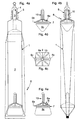
- the fourth example of a thrust member 6 according to the invention can be seen in particular in FIGS. 4c-4e.
- the upper part 6 a has the shape of a truncated cone with a square cross-section and is provided with the projection 10.
- the middle part 6b has the shape of a parallelepiped with a square cross section and the stripping clamp 7, while the lower part 6c has an irregular shape.
- the irregular shape of the lower part 6c is that, as can be seen in particular in Figure 4c, which results from the fact that its lower part with an approximately elliptical, very squashed, almost rectangular cross-section connects to its upper part with a square cross-section.
- the fifth example of a thrust member 6 according to the invention can be seen in particular in FIGS. 5c-5e.
- the upper part 6a and the middle part 6b are the same as those of the above-mentioned fourth example.
- the lower part 6c results by decreasing material to a lower part 6c, like that of the fourth example mentioned above, to form a shaped recess 8.
- This shaped recess 8 is intended to receive the thumb of the user's hand and facilitates the exercise of the external thrust action.
- FIGS. 6c-6e The sixth example of a thrust member 6 according to the invention can be seen in particular in FIGS. 6c-6e.
- the upper part 6a has the shape of a truncated cone with a square cross section and is provided with the projection 10, while the middle part 6b in the form of a parallelepiped with square cross section and the Abstreifschelle 7 on.
- the lower part 6c has the shape of a hemisphere, so that thanks to the symmetry of this part, the thrust external action exerted by the user's hand can take place in any position because, unlike the case of the presence of the shaped recess 8, a preferred direction is missing.
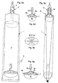
- the seventh example of a thrust member 6 according to the invention can be seen in particular in FIGS. 7c-7e.
- the upper part 6 a has the shape of a truncated cone with an elliptical cross section and is provided with the projection 10.
- the middle part 6b has the shape of a cylinder with an elliptical cross section and the stripping clamp 7, while the lower part 6c has an irregular shape.
- the irregular shape of the lower part 6c is that, as can be seen in particular in Figure 1c, which results from the fact that its lower part with an approximately elliptical, very squashed, almost rectangular cross-section connects to the upper part with an elliptical cross section.
- FIGS. 8c-8e The eighth example of a thrust member 6 according to the invention can be seen in particular in FIGS. 8c-8e.
- the upper part 6a and the middle part 6b are the same as those of the above-mentioned seventh example.
- the lower part 6c is obtained by decreasing material to a lower part 6c, like that of the seventh example mentioned above, to form a shaped recess 8.
- This shaped recess 8 is intended to receive the thumb of the user's hand and facilitates the exercise of the external thrust action.
- the ninth example of a thrust member 6 according to the invention can be seen in particular in FIGS. 9c-9e.
- the upper part 6a has the shape of a truncated cone with an elliptical cross section and is provided with the projection 10, while the middle part 6b is in the form of a cylinder having elliptical cross section and the Abstreifschelle 7.
- the lower part 6c has the shape of a semi-ellipsoid, so that thanks to the symmetry of this part, the thrust external action exerted by the user's hand can take place in any position because, unlike the case of the presence of the shaped recess 8, a preferred direction is missing.
- the user removes the closure element 5. Subsequently, he will press with the fingers of the hand on the deformable hollow body 1, on the thrust member 6 upper region, which is easily recognized by probing.
- the pressure exerted by the fingers of the hand exerts on its part a pushing action on the underlying thrust member 6, in particular on the lower part 6 c.
- the thrust member 6 slides by a certain distance in the direction of the inlet and outlet channel 3.
- the upper part 6a pushes the paste or cream 2 and puts it under pressure, while the middle part 6b by means of the Abstreifschelle 7 prevents the paste or cream 2 escapes into the empty, the thrust member 6 underlying area of the hollow body 1.
- the thrust member 6 is in the end portion of its sliding, close to the entrance and exit channel 3 and the paste or cream 2 will be in or near the inlet and outlet channel 3, the user of the container according to the invention will not have to take any special measures to allow the remainder of the paste or cream 2 to escape.
Landscapes
- Engineering & Computer Science (AREA)
- Mechanical Engineering (AREA)
- Containers And Packaging Bodies Having A Special Means To Remove Contents (AREA)
- Cosmetics (AREA)
- Dairy Products (AREA)
- Tubes (AREA)
Claims (13)
- Récipient pour substances fluides (2) comme des pâtes ou des crèmes, c'est-à-dire des substances qui prennent la forme du récipient qui les contient bien que ne possédant pas un volume propre, comprenant:un corps creux déformable (1) où se trouve la substance fluide (2) et qui montre un canal d'entrée et sortie (3) sur l'extrémité duquel est prévue une ouverture d'entrée et sortie (4), etun élément de fermeture (5) reliable au canal d'entrée et sortie (3) pour empêcher la sortie de la substance fluide (2), etun organe de poussée (6) qui se trouve dépourvu de liens à l'intérieur du corps creux (1) et est donc en mesure de se déplacer sous l'effet d'une action de poussée exercée de l'extérieur, et est placé à l'intérieur du corps creux (1) de manière à ce que la substance fluide (2) se trouve dans l'espace compris entre lui et l'ouverture d'entrée et sortie (4), où l'organe de poussée (6) présente une partie supérieure (6a) qui se trouve au contact de la substance fluide (2) sus-jacente et montre une section maximale égale à celle du corps creux (1) et une partie inférieure (6c) soumise à l'action de poussée externe, caractérisée en ce que sur la superficie de la partie supérieure (6a) sont prévus de petits canaux ouverts (9) où peut passer la substance fluide (2).
- Récipient suivant la revendication 1, caractérisé en ce que la partie supérieure (6a) présente un dépassement (10) dans la direction de l'ouverture d'entrée et sortie (4), qui dans la partie finale du déplacement de l'organe de poussée (6) pénètre à l'intérieur de l'ouverture d'entrée et sortie (4) de manière à pousser vers l'extérieur tout possible résidu de substance fluide (2) présent sur elle, et que les petits canaux ouverts (9) s'étendent aussi le long de la superficie du dépassement (10), de manière à ce que la substance fluide (2) qui passe à l'intérieur puisse arriver au canal d'entrée et sortie (3).
- Récipient suivant la revendication 1, caractérisé en ce que l'organe de poussée (6) présente aussi une partie intermédiaire (6b) dont la section est régulière et est identique à celle du corps creux (1), où sur la superficie de la partie intermédiaire (6b) est placé un segment racleur (7) apte à racler la superficie interne du corps creux (1) pendant le déplacement de l'organe de poussée (6).
- Récipient suivant la revendication 2, caractérisé en ce que la partie supérieure (6a) présente la forme d'un tronc de cône à section ronde, la partie intermédiaire (6b) présente la forme d'un cylindre à section ronde et la partie inférieure (6c) présente une forme irrégulière dérivant du fait que sa partie basse, ayant une section approximativement elliptique, très aplatie, presque rectangulaire, se relie à sa partie haute, ayant une section ronde.
- Récipient suivant la revendication 3, caractérisé en ce qu'on enlève le matériau de la partie inférieure (6c) de manière à créer un retrait profilé (8).
- Récipient suivant la revendication 2, caractérisé en ce que la partie supérieure (6a) présente la forme d'un tronc de cône à section ronde, la partie intermédiaire (6b) présente la forme d'un cylindre à section ronde et la partie inférieure (6c) présente la forme d'une demi-sphère.
- Récipient suivant la revendication 2, caractérisé en ce que la partie supérieure (6a) présente la forme d'un tronc de cône à section carrée, la partie intermédiaire (6b) présente la forme d'un parallélépipède à section carrée et la partie inférieure (6c) présente une forme irrégulière dérivant du fait que sa partie basse, ayant une section approximativement elliptique, très aplatie, presque rectangulaire, se relie à sa partie haute, ayant une section carrée.
- Récipient suivant la revendication 6, caractérisée en ce qu'on enlève du matériel de la partie inférieure (6c) de manière à créer un retrait profilé (8).
- Récipient suivant la revendication 2, caractérisé en ce que la partie supérieure (6a) présente la forme d'un tronc de cône à section carrée, la partie intermédiaire (6b) présente la forme d'un parallélépipède à section carrée et la partie inférieure (6c) présente la forme d'une demi-sphère.
- Récipient suivant la revendication 2, caractérisé en ce que la partie supérieure (6a) présente la forme d'un tronc de cône à section elliptique, la partie intermédiaire (6b) présente la forme d'un cylindre à section elliptique et la partie inférieure (6c) présente une forme irrégulière dérivant du fait que sa partie basse, ayant une section approximativement elliptique, très aplatie, presque rectangulaire, se relie à sa partie haute, ayant une section elliptique.
- Récipient suivant la revendication 9, caractérisé en ce qu'on enlève de la matière de la partie inférieure (6c) de manière à créer un retrait profilé (8).
- Récipient suivant la revendication 2, caractérisé en ce que la partie supérieure (6a) présente la forme d'un tronc de cône elliptique, la partie centrale (6b) présente la forme d'un cylindre à section elliptique et la partie inférieure (6c) présente la forme d'un demi-ellipsoïde.
- Récipient suivant une des revendications de 1 à 12, caractérisé en ce que la partie inférieure (6c) est réalisée en un matériau élastique souple.
Applications Claiming Priority (1)
| Application Number | Priority Date | Filing Date | Title |
|---|---|---|---|
| PCT/IT2002/000688 WO2004039685A1 (fr) | 2002-10-29 | 2002-10-29 | Recipient pour matieres coulantes telles que des pates et des cremes |
Publications (2)
| Publication Number | Publication Date |
|---|---|
| EP1597162A1 EP1597162A1 (fr) | 2005-11-23 |
| EP1597162B1 true EP1597162B1 (fr) | 2006-12-13 |
Family
ID=32259867
Family Applications (1)
| Application Number | Title | Priority Date | Filing Date |
|---|---|---|---|
| EP02788543A Expired - Lifetime EP1597162B1 (fr) | 2002-10-29 | 2002-10-29 | Recipient pour matieres coulantes telles que des pates et des cremes |
Country Status (8)
| Country | Link |
|---|---|
| US (1) | US20070062977A1 (fr) |
| EP (1) | EP1597162B1 (fr) |
| AT (1) | ATE348050T1 (fr) |
| AU (1) | AU2002353518A1 (fr) |
| DE (1) | DE50208974D1 (fr) |
| ES (1) | ES2278991T3 (fr) |
| PT (1) | PT1597162E (fr) |
| WO (1) | WO2004039685A1 (fr) |
Families Citing this family (15)
| Publication number | Priority date | Publication date | Assignee | Title |
|---|---|---|---|---|
| GB2433486B (en) * | 2005-12-10 | 2008-07-09 | William Arthur Bell | Deformable dispensing tube |
| WO2008047188A1 (fr) * | 2006-10-20 | 2008-04-24 | Albertus Johannes Human | Piston plongeur |
| US20080302826A1 (en) * | 2007-06-09 | 2008-12-11 | Rich Jr Joseph | Plunger tube |
| KR100932779B1 (ko) * | 2008-02-13 | 2009-12-21 | 임형준 | 잔량제거수단을 갖는 튜브형 용기 |
| KR200447897Y1 (ko) * | 2008-06-23 | 2010-03-04 | 신민욱 | 절약형 치약용기 |
| KR101022595B1 (ko) | 2010-01-27 | 2011-03-16 | 우종원 | 점성물질 인출피스톤을 갖는 튜브용기 |
| WO2011087335A2 (fr) * | 2010-02-23 | 2011-07-21 | Woo Jong Won | Contenant tubulaire pourvu d'un piston servant à distribuer des substances visqueuses |
| US20120085786A1 (en) * | 2010-10-12 | 2012-04-12 | Marc Mamiye | Pinch tube with internal piston dispensing extractor |
| EP2647583A1 (fr) * | 2012-04-03 | 2013-10-09 | Marc Mamiye | Tube de pincement extracteur de distribution avec piston interne |
| TW201502018A (zh) * | 2013-04-09 | 2015-01-16 | Veycle Design Co Ltd | 管狀軟管環保裝置結構 |
| KR101331846B1 (ko) * | 2013-05-15 | 2013-12-03 | 주식회사 우경아이앤아이 | 내용물 배출용기 |
| WO2016113188A1 (fr) * | 2015-01-15 | 2016-07-21 | Enzo Ferrarin | Distributeur amélioré pour récipients pour substances fluides |
| WO2016113186A1 (fr) | 2015-01-15 | 2016-07-21 | Enzo Ferrarin | Contenant pour substances coulantes |
| CN112313159B (zh) * | 2018-04-27 | 2022-09-30 | 约尔·沙洛维茨 | 食物容器和分配器 |
| IL267706B (en) * | 2019-06-27 | 2021-07-29 | Harris Hilll | Portable ointment dispenser |
Family Cites Families (11)
| Publication number | Priority date | Publication date | Assignee | Title |
|---|---|---|---|---|
| US2789731A (en) * | 1955-06-06 | 1957-04-23 | Leonard L Marraffino | Striping dispenser |
| US3297207A (en) * | 1964-04-28 | 1967-01-10 | Ballin Gene | Collapsible tubes with follower and the method of filling thereof |
| US3493147A (en) * | 1968-02-05 | 1970-02-03 | Gene Ballin | Collapsible tube and follower |
| US3827607A (en) * | 1971-08-26 | 1974-08-06 | Eyelet Specialty Co | Pressure operated container for dispensing viscous products |
| DE2339177A1 (de) * | 1973-08-02 | 1975-02-13 | Voormann Louis Ing Gmbh | Verpackungsanordnung fuer stifte, pastoese massen od.dgl |
| US5020694A (en) * | 1989-03-16 | 1991-06-04 | Chesebrough-Pond's, Inc. | Multi-cavity dispensing container |
| GB2257108A (en) * | 1991-06-25 | 1993-01-06 | John David Sheppard | Dispensing contents of sqeezable containers |
| DE9110529U1 (de) * | 1991-08-26 | 1991-10-10 | Prestele, Eugen, 8900 Augsburg | Kartusche |
| NZ519006A (en) * | 1999-11-10 | 2006-12-22 | Scholle Corp | Collapsible bag for dispensing liquids and method |
| US20020148854A1 (en) * | 2001-04-16 | 2002-10-17 | Egerhazy Joseph Bela | Flexible tube dispenser for viscous materials with movable insert and method of assembly |
| US6474511B1 (en) * | 2001-08-31 | 2002-11-05 | Sonoco Development, Inc. | Safety cap for fluid dispensing cartridges |
-
2002
- 2002-10-29 AT AT02788543T patent/ATE348050T1/de not_active IP Right Cessation
- 2002-10-29 AU AU2002353518A patent/AU2002353518A1/en not_active Abandoned
- 2002-10-29 DE DE50208974T patent/DE50208974D1/de not_active Expired - Fee Related
- 2002-10-29 US US10/532,844 patent/US20070062977A1/en not_active Abandoned
- 2002-10-29 EP EP02788543A patent/EP1597162B1/fr not_active Expired - Lifetime
- 2002-10-29 WO PCT/IT2002/000688 patent/WO2004039685A1/fr not_active Ceased
- 2002-10-29 PT PT02788543T patent/PT1597162E/pt unknown
- 2002-10-29 ES ES02788543T patent/ES2278991T3/es not_active Expired - Lifetime
Also Published As
| Publication number | Publication date |
|---|---|
| US20070062977A1 (en) | 2007-03-22 |
| ATE348050T1 (de) | 2007-01-15 |
| WO2004039685A1 (fr) | 2004-05-13 |
| ES2278991T3 (es) | 2007-08-16 |
| AU2002353518A1 (en) | 2004-05-25 |
| DE50208974D1 (de) | 2007-01-25 |
| EP1597162A1 (fr) | 2005-11-23 |
| PT1597162E (pt) | 2007-03-30 |
Similar Documents
| Publication | Publication Date | Title |
|---|---|---|
| EP1597162B1 (fr) | Recipient pour matieres coulantes telles que des pates et des cremes | |
| EP1555952B1 (fr) | Dispositif de stockage et d'application de substances visqueuses | |
| DE10056212B4 (de) | Vorrichtung zum Lagern und Ausbringen von fließfähigen Zusammensetzungen, Verfahren zur Herstellung und Verwendung der Vorrichtung | |
| EP1240087B1 (fr) | Dispositif pour stocker et distribuer une substance coulante | |
| EP2480271A2 (fr) | Contenant scellé pourvu d'un piston coulissant | |
| DE102012214259A1 (de) | Katheter-Set | |
| DE3202275A1 (de) | Einhandbetaetigter behaelter zur abgabe gleicher oder verschiedener volumenmengen viskoser fuellgueter sowie seine befuellung | |
| DE60119136T2 (de) | Beutel zum verpacken einer substanz mit integrierter kanüle und band aus solchen beuteln | |
| DE2910310A1 (de) | Vorrichtung zur abgabe eines fluids aus einem behaelter | |
| DE69312510T2 (de) | Nachfüllbarer mehrkammer-spender und nachfüllpatrone | |
| DE3324780A1 (de) | Vorrichtung zur intra-analen applikation von fluessigen oder pastoesen wirkstoffzubereitungen | |
| WO2011000353A1 (fr) | Ensemble cathéter | |
| EP0315077A1 (fr) | Distributeur pour produits pâteux | |
| EP0245502B1 (fr) | Distributeur de substances pateuses ou fluides | |
| DE3523891C2 (de) | Füllzahnbürste | |
| EP0078471A2 (fr) | Récipient à vidage par pression | |
| DE2711208C2 (de) | Vorrichtung zum Dosieren und Abfüllen insbesondere hochviskoser Medien | |
| DE102009033400A1 (de) | Vaginaldusche | |
| WO2010118764A1 (fr) | Appareil de pompage de liquide | |
| DE10200748A1 (de) | Verschließbare Abgabevorrichtung zur Abgabe eines in einem Behälter enthaltenen flüssigen, viskosen oder pastösen Mediums | |
| DE2625981C2 (de) | Vorrichtung zum Ausgießen von Flüssigkeiten aus Behältern | |
| EP1703936A1 (fr) | Dispositif pour traiter des troubles de vidage de la vessie chez un etre humain | |
| CH674191A5 (fr) | ||
| DE2517793A1 (de) | Packung mit zwei kammern | |
| EP2419162B1 (fr) | Appareil de pompage de liquide |
Legal Events
| Date | Code | Title | Description |
|---|---|---|---|
| PUAI | Public reference made under article 153(3) epc to a published international application that has entered the european phase |
Free format text: ORIGINAL CODE: 0009012 |
|
| 17P | Request for examination filed |
Effective date: 20050527 |
|
| AK | Designated contracting states |
Kind code of ref document: A1 Designated state(s): AT BE BG CH CY CZ DE DK EE ES FI FR GB GR IE IT LI LU MC NL PT SE SK TR |
|
| AX | Request for extension of the european patent |
Extension state: AL LT LV MK RO SI |
|
| DAX | Request for extension of the european patent (deleted) | ||
| GRAP | Despatch of communication of intention to grant a patent |
Free format text: ORIGINAL CODE: EPIDOSNIGR1 |
|
| GRAS | Grant fee paid |
Free format text: ORIGINAL CODE: EPIDOSNIGR3 |
|
| GRAA | (expected) grant |
Free format text: ORIGINAL CODE: 0009210 |
|
| AK | Designated contracting states |
Kind code of ref document: B1 Designated state(s): AT BE BG CH CY CZ DE DK EE ES FI FR GB GR IE IT LI LU MC NL PT SE SK TR |
|
| PG25 | Lapsed in a contracting state [announced via postgrant information from national office to epo] |
Ref country code: SK Free format text: LAPSE BECAUSE OF FAILURE TO SUBMIT A TRANSLATION OF THE DESCRIPTION OR TO PAY THE FEE WITHIN THE PRESCRIBED TIME-LIMIT Effective date: 20061213 Ref country code: CZ Free format text: LAPSE BECAUSE OF FAILURE TO SUBMIT A TRANSLATION OF THE DESCRIPTION OR TO PAY THE FEE WITHIN THE PRESCRIBED TIME-LIMIT Effective date: 20061213 Ref country code: FI Free format text: LAPSE BECAUSE OF FAILURE TO SUBMIT A TRANSLATION OF THE DESCRIPTION OR TO PAY THE FEE WITHIN THE PRESCRIBED TIME-LIMIT Effective date: 20061213 Ref country code: DK Free format text: LAPSE BECAUSE OF FAILURE TO SUBMIT A TRANSLATION OF THE DESCRIPTION OR TO PAY THE FEE WITHIN THE PRESCRIBED TIME-LIMIT Effective date: 20061213 |
|
| REG | Reference to a national code |
Ref country code: GB Ref legal event code: FG4D Free format text: NOT ENGLISH |
|
| REG | Reference to a national code |
Ref country code: CH Ref legal event code: EP |
|
| REG | Reference to a national code |
Ref country code: IE Ref legal event code: FG4D Free format text: LANGUAGE OF EP DOCUMENT: GERMAN |
|
| REF | Corresponds to: |
Ref document number: 50208974 Country of ref document: DE Date of ref document: 20070125 Kind code of ref document: P |
|
| PG25 | Lapsed in a contracting state [announced via postgrant information from national office to epo] |
Ref country code: BG Free format text: LAPSE BECAUSE OF FAILURE TO SUBMIT A TRANSLATION OF THE DESCRIPTION OR TO PAY THE FEE WITHIN THE PRESCRIBED TIME-LIMIT Effective date: 20070313 Ref country code: SE Free format text: LAPSE BECAUSE OF FAILURE TO SUBMIT A TRANSLATION OF THE DESCRIPTION OR TO PAY THE FEE WITHIN THE PRESCRIBED TIME-LIMIT Effective date: 20070313 |
|
| REG | Reference to a national code |
Ref country code: PT Ref legal event code: SC4A Free format text: AVAILABILITY OF NATIONAL TRANSLATION Effective date: 20070309 |
|
| GBT | Gb: translation of ep patent filed (gb section 77(6)(a)/1977) |
Effective date: 20070321 |
|
| REG | Reference to a national code |
Ref country code: CH Ref legal event code: NV Representative=s name: BUGNION S.A. |
|
| ET | Fr: translation filed | ||
| REG | Reference to a national code |
Ref country code: ES Ref legal event code: FG2A Ref document number: 2278991 Country of ref document: ES Kind code of ref document: T3 |
|
| PLBE | No opposition filed within time limit |
Free format text: ORIGINAL CODE: 0009261 |
|
| STAA | Information on the status of an ep patent application or granted ep patent |
Free format text: STATUS: NO OPPOSITION FILED WITHIN TIME LIMIT |
|
| 26N | No opposition filed |
Effective date: 20070914 |
|
| PGFP | Annual fee paid to national office [announced via postgrant information from national office to epo] |
Ref country code: DE Payment date: 20071101 Year of fee payment: 6 Ref country code: ES Payment date: 20071119 Year of fee payment: 6 Ref country code: NL Payment date: 20071029 Year of fee payment: 6 |
|
| PGFP | Annual fee paid to national office [announced via postgrant information from national office to epo] |
Ref country code: CH Payment date: 20071114 Year of fee payment: 6 Ref country code: IT Payment date: 20071030 Year of fee payment: 6 Ref country code: AT Payment date: 20071113 Year of fee payment: 6 |
|
| PGFP | Annual fee paid to national office [announced via postgrant information from national office to epo] |
Ref country code: BE Payment date: 20071130 Year of fee payment: 6 |
|
| PG25 | Lapsed in a contracting state [announced via postgrant information from national office to epo] |
Ref country code: GR Free format text: LAPSE BECAUSE OF FAILURE TO SUBMIT A TRANSLATION OF THE DESCRIPTION OR TO PAY THE FEE WITHIN THE PRESCRIBED TIME-LIMIT Effective date: 20070314 |
|
| PGFP | Annual fee paid to national office [announced via postgrant information from national office to epo] |
Ref country code: FR Payment date: 20071031 Year of fee payment: 6 Ref country code: GB Payment date: 20071031 Year of fee payment: 6 |
|
| PG25 | Lapsed in a contracting state [announced via postgrant information from national office to epo] |
Ref country code: MC Free format text: LAPSE BECAUSE OF NON-PAYMENT OF DUE FEES Effective date: 20071031 |
|
| PGFP | Annual fee paid to national office [announced via postgrant information from national office to epo] |
Ref country code: PT Payment date: 20071026 Year of fee payment: 6 |
|
| PG25 | Lapsed in a contracting state [announced via postgrant information from national office to epo] |
Ref country code: EE Free format text: LAPSE BECAUSE OF FAILURE TO SUBMIT A TRANSLATION OF THE DESCRIPTION OR TO PAY THE FEE WITHIN THE PRESCRIBED TIME-LIMIT Effective date: 20061213 |
|
| BERE | Be: lapsed |
Owner name: FERRARIN, ENZO Effective date: 20081031 |
|
| REG | Reference to a national code |
Ref country code: PT Ref legal event code: MM4A Free format text: LAPSE DUE TO NON-PAYMENT OF FEES Effective date: 20090429 |
|
| REG | Reference to a national code |
Ref country code: CH Ref legal event code: PL |
|
| GBPC | Gb: european patent ceased through non-payment of renewal fee |
Effective date: 20081029 |
|
| NLV4 | Nl: lapsed or anulled due to non-payment of the annual fee |
Effective date: 20090501 |
|
| REG | Reference to a national code |
Ref country code: FR Ref legal event code: ST Effective date: 20090630 |
|
| PG25 | Lapsed in a contracting state [announced via postgrant information from national office to epo] |
Ref country code: NL Free format text: LAPSE BECAUSE OF NON-PAYMENT OF DUE FEES Effective date: 20090501 |
|
| PG25 | Lapsed in a contracting state [announced via postgrant information from national office to epo] |
Ref country code: AT Free format text: LAPSE BECAUSE OF NON-PAYMENT OF DUE FEES Effective date: 20081029 Ref country code: PT Free format text: LAPSE BECAUSE OF NON-PAYMENT OF DUE FEES Effective date: 20090429 Ref country code: CY Free format text: LAPSE BECAUSE OF FAILURE TO SUBMIT A TRANSLATION OF THE DESCRIPTION OR TO PAY THE FEE WITHIN THE PRESCRIBED TIME-LIMIT Effective date: 20061213 Ref country code: LU Free format text: LAPSE BECAUSE OF NON-PAYMENT OF DUE FEES Effective date: 20071029 Ref country code: IT Free format text: LAPSE BECAUSE OF NON-PAYMENT OF DUE FEES Effective date: 20081029 Ref country code: DE Free format text: LAPSE BECAUSE OF NON-PAYMENT OF DUE FEES Effective date: 20090501 |
|
| PGFP | Annual fee paid to national office [announced via postgrant information from national office to epo] |
Ref country code: IE Payment date: 20071113 Year of fee payment: 6 |
|
| PG25 | Lapsed in a contracting state [announced via postgrant information from national office to epo] |
Ref country code: BE Free format text: LAPSE BECAUSE OF NON-PAYMENT OF DUE FEES Effective date: 20081031 Ref country code: TR Free format text: LAPSE BECAUSE OF FAILURE TO SUBMIT A TRANSLATION OF THE DESCRIPTION OR TO PAY THE FEE WITHIN THE PRESCRIBED TIME-LIMIT Effective date: 20061213 |
|
| PG25 | Lapsed in a contracting state [announced via postgrant information from national office to epo] |
Ref country code: LI Free format text: LAPSE BECAUSE OF NON-PAYMENT OF DUE FEES Effective date: 20081031 Ref country code: CH Free format text: LAPSE BECAUSE OF NON-PAYMENT OF DUE FEES Effective date: 20081031 Ref country code: IE Free format text: LAPSE BECAUSE OF NON-PAYMENT OF DUE FEES Effective date: 20081029 Ref country code: FR Free format text: LAPSE BECAUSE OF NON-PAYMENT OF DUE FEES Effective date: 20081031 |
|
| PG25 | Lapsed in a contracting state [announced via postgrant information from national office to epo] |
Ref country code: GB Free format text: LAPSE BECAUSE OF NON-PAYMENT OF DUE FEES Effective date: 20081029 |
|
| REG | Reference to a national code |
Ref country code: ES Ref legal event code: FD2A Effective date: 20081030 |
|
| PG25 | Lapsed in a contracting state [announced via postgrant information from national office to epo] |
Ref country code: ES Free format text: LAPSE BECAUSE OF NON-PAYMENT OF DUE FEES Effective date: 20081030 |