EP1597576B1 - Dispositif d'arret capillaire - Google Patents
Dispositif d'arret capillaire Download PDFInfo
- Publication number
- EP1597576B1 EP1597576B1 EP04713620A EP04713620A EP1597576B1 EP 1597576 B1 EP1597576 B1 EP 1597576B1 EP 04713620 A EP04713620 A EP 04713620A EP 04713620 A EP04713620 A EP 04713620A EP 1597576 B1 EP1597576 B1 EP 1597576B1
- Authority
- EP
- European Patent Office
- Prior art keywords
- membrane
- inlet
- outlet
- aperture
- silicon
- Prior art date
- Legal status (The legal status is an assumption and is not a legal conclusion. Google has not performed a legal analysis and makes no representation as to the accuracy of the status listed.)
- Expired - Lifetime
Links
Images


Classifications
-
- F—MECHANICAL ENGINEERING; LIGHTING; HEATING; WEAPONS; BLASTING
- F04—POSITIVE - DISPLACEMENT MACHINES FOR LIQUIDS; PUMPS FOR LIQUIDS OR ELASTIC FLUIDS
- F04B—POSITIVE-DISPLACEMENT MACHINES FOR LIQUIDS; PUMPS
- F04B19/00—Machines or pumps having pertinent characteristics not provided for in, or of interest apart from, groups F04B1/00 - F04B17/00
- F04B19/006—Micropumps
-
- B—PERFORMING OPERATIONS; TRANSPORTING
- B01—PHYSICAL OR CHEMICAL PROCESSES OR APPARATUS IN GENERAL
- B01L—CHEMICAL OR PHYSICAL LABORATORY APPARATUS FOR GENERAL USE
- B01L3/00—Containers or dishes for laboratory use, e.g. laboratory glassware; Droppers
- B01L3/50—Containers for the purpose of retaining a material to be analysed, e.g. test tubes
- B01L3/502—Containers for the purpose of retaining a material to be analysed, e.g. test tubes with fluid transport, e.g. in multi-compartment structures
- B01L3/5027—Containers for the purpose of retaining a material to be analysed, e.g. test tubes with fluid transport, e.g. in multi-compartment structures by integrated microfluidic structures, i.e. dimensions of channels and chambers are such that surface tension forces are important, e.g. lab-on-a-chip
- B01L3/50273—Containers for the purpose of retaining a material to be analysed, e.g. test tubes with fluid transport, e.g. in multi-compartment structures by integrated microfluidic structures, i.e. dimensions of channels and chambers are such that surface tension forces are important, e.g. lab-on-a-chip characterised by the means or forces applied to move the fluids
-
- B—PERFORMING OPERATIONS; TRANSPORTING
- B01—PHYSICAL OR CHEMICAL PROCESSES OR APPARATUS IN GENERAL
- B01L—CHEMICAL OR PHYSICAL LABORATORY APPARATUS FOR GENERAL USE
- B01L3/00—Containers or dishes for laboratory use, e.g. laboratory glassware; Droppers
- B01L3/50—Containers for the purpose of retaining a material to be analysed, e.g. test tubes
- B01L3/502—Containers for the purpose of retaining a material to be analysed, e.g. test tubes with fluid transport, e.g. in multi-compartment structures
- B01L3/5027—Containers for the purpose of retaining a material to be analysed, e.g. test tubes with fluid transport, e.g. in multi-compartment structures by integrated microfluidic structures, i.e. dimensions of channels and chambers are such that surface tension forces are important, e.g. lab-on-a-chip
- B01L3/502738—Containers for the purpose of retaining a material to be analysed, e.g. test tubes with fluid transport, e.g. in multi-compartment structures by integrated microfluidic structures, i.e. dimensions of channels and chambers are such that surface tension forces are important, e.g. lab-on-a-chip characterised by integrated valves
-
- F—MECHANICAL ENGINEERING; LIGHTING; HEATING; WEAPONS; BLASTING
- F16—ENGINEERING ELEMENTS AND UNITS; GENERAL MEASURES FOR PRODUCING AND MAINTAINING EFFECTIVE FUNCTIONING OF MACHINES OR INSTALLATIONS; THERMAL INSULATION IN GENERAL
- F16K—VALVES; TAPS; COCKS; ACTUATING-FLOATS; DEVICES FOR VENTING OR AERATING
- F16K99/00—Subject matter not provided for in other groups of this subclass
- F16K99/0001—Microvalves
- F16K99/0003—Constructional types of microvalves; Details of the cutting-off member
- F16K99/0015—Diaphragm or membrane valves
-
- F—MECHANICAL ENGINEERING; LIGHTING; HEATING; WEAPONS; BLASTING
- F16—ENGINEERING ELEMENTS AND UNITS; GENERAL MEASURES FOR PRODUCING AND MAINTAINING EFFECTIVE FUNCTIONING OF MACHINES OR INSTALLATIONS; THERMAL INSULATION IN GENERAL
- F16K—VALVES; TAPS; COCKS; ACTUATING-FLOATS; DEVICES FOR VENTING OR AERATING
- F16K99/00—Subject matter not provided for in other groups of this subclass
- F16K99/0001—Microvalves
- F16K99/0034—Operating means specially adapted for microvalves
- F16K99/0055—Operating means specially adapted for microvalves actuated by fluids
- F16K99/0059—Operating means specially adapted for microvalves actuated by fluids actuated by a pilot fluid
-
- B—PERFORMING OPERATIONS; TRANSPORTING
- B01—PHYSICAL OR CHEMICAL PROCESSES OR APPARATUS IN GENERAL
- B01L—CHEMICAL OR PHYSICAL LABORATORY APPARATUS FOR GENERAL USE
- B01L2200/00—Solutions for specific problems relating to chemical or physical laboratory apparatus
- B01L2200/12—Specific details about manufacturing devices
-
- B—PERFORMING OPERATIONS; TRANSPORTING
- B01—PHYSICAL OR CHEMICAL PROCESSES OR APPARATUS IN GENERAL
- B01L—CHEMICAL OR PHYSICAL LABORATORY APPARATUS FOR GENERAL USE
- B01L2400/00—Moving or stopping fluids
- B01L2400/04—Moving fluids with specific forces or mechanical means
- B01L2400/0475—Moving fluids with specific forces or mechanical means specific mechanical means and fluid pressure
- B01L2400/0487—Moving fluids with specific forces or mechanical means specific mechanical means and fluid pressure fluid pressure, pneumatics
-
- B—PERFORMING OPERATIONS; TRANSPORTING
- B01—PHYSICAL OR CHEMICAL PROCESSES OR APPARATUS IN GENERAL
- B01L—CHEMICAL OR PHYSICAL LABORATORY APPARATUS FOR GENERAL USE
- B01L2400/00—Moving or stopping fluids
- B01L2400/06—Valves, specific forms thereof
- B01L2400/0688—Valves, specific forms thereof surface tension valves, capillary stop, capillary break
-
- B—PERFORMING OPERATIONS; TRANSPORTING
- B01—PHYSICAL OR CHEMICAL PROCESSES OR APPARATUS IN GENERAL
- B01L—CHEMICAL OR PHYSICAL LABORATORY APPARATUS FOR GENERAL USE
- B01L3/00—Containers or dishes for laboratory use, e.g. laboratory glassware; Droppers
- B01L3/50—Containers for the purpose of retaining a material to be analysed, e.g. test tubes
- B01L3/502—Containers for the purpose of retaining a material to be analysed, e.g. test tubes with fluid transport, e.g. in multi-compartment structures
- B01L3/5027—Containers for the purpose of retaining a material to be analysed, e.g. test tubes with fluid transport, e.g. in multi-compartment structures by integrated microfluidic structures, i.e. dimensions of channels and chambers are such that surface tension forces are important, e.g. lab-on-a-chip
- B01L3/502723—Containers for the purpose of retaining a material to be analysed, e.g. test tubes with fluid transport, e.g. in multi-compartment structures by integrated microfluidic structures, i.e. dimensions of channels and chambers are such that surface tension forces are important, e.g. lab-on-a-chip characterised by venting arrangements
-
- F—MECHANICAL ENGINEERING; LIGHTING; HEATING; WEAPONS; BLASTING
- F16—ENGINEERING ELEMENTS AND UNITS; GENERAL MEASURES FOR PRODUCING AND MAINTAINING EFFECTIVE FUNCTIONING OF MACHINES OR INSTALLATIONS; THERMAL INSULATION IN GENERAL
- F16K—VALVES; TAPS; COCKS; ACTUATING-FLOATS; DEVICES FOR VENTING OR AERATING
- F16K99/00—Subject matter not provided for in other groups of this subclass
- F16K2099/0073—Fabrication methods specifically adapted for microvalves
- F16K2099/0074—Fabrication methods specifically adapted for microvalves using photolithography, e.g. etching
-
- F—MECHANICAL ENGINEERING; LIGHTING; HEATING; WEAPONS; BLASTING
- F16—ENGINEERING ELEMENTS AND UNITS; GENERAL MEASURES FOR PRODUCING AND MAINTAINING EFFECTIVE FUNCTIONING OF MACHINES OR INSTALLATIONS; THERMAL INSULATION IN GENERAL
- F16K—VALVES; TAPS; COCKS; ACTUATING-FLOATS; DEVICES FOR VENTING OR AERATING
- F16K99/00—Subject matter not provided for in other groups of this subclass
- F16K2099/0082—Microvalves adapted for a particular use
- F16K2099/0084—Chemistry or biology, e.g. "lab-on-a-chip" technology
Definitions
- This invention relates to a system having one or more fluidic channels with sub-millimetre dimensions.
- Such systems are used within the fields of chemistry, bio-chemistry, molecular and cell biology and are often termed microfluidic systems.
- Systems to which the present invention relate may be used to monitor electrophysiological properties of ion channels in ion channel- containing structures, typically lipid membrane-containing structures such as cells, by establishing an electrophysiological measuring configuration in which a cell membrane forms a high resistive seal around the measuring electrode, making it possible to determine and monitor a current flow through the cell membrane.
- Such systems can form part of an apparatus for carrying out patch clamp techniques utilised to study ion transfer channels and biological membranes, for example.
- Ion channels are transmembrane proteins which catalyse transport of inorganic ions across cell membranes.
- the ion channels participate in processes as diverse as generating and timing action potentials, synaptic transmission, secretion of hormones, contraction of muscles, etc.
- Many pharmacological agents exert their specific effects via modulation of ion channels.
- Examples include antiepileptic compounds such as phenytoin and lamotrigine, which block voltage-dependent Na+-channels in the brain, antihypertensive drugs such as nifedipine and diltiazem, which block voltage dependent Ca2+-channels in smooth muscle cells, and stimulators of insulin release such as glibenclamide and tolbutamide, which block an ATP-regulated K+-channel in the pancreas.
- the patch clamp technique has enabled scientists to perform manipulations with voltage-dependent channels. These techniques include adjusting the polarity of the electrode in the patch pipette and altering the saline composition to moderate the free ion levels in the bath solution.
- the patch clamp technique represents a major development in biology and medicine, since it enables measurement of ion flow through single ion channel proteins, and also enables the study of a single ion channel activity in response to drug exposure.
- a thin (approx. 0.5-2 ⁇ m in diameter) glass pipette is used. The tip of this patch pipette is pressed against the surface of the cell membrane. The pipette tip seals tightly to the cell membrane and isolates a small population of ion channel proteins in the tiny patch of membrane limited by the pipette orifice.
- the activity of these channels can be measured individually ('single channel recording') or, alternatively, the patch can be ruptured, allowing measurements of the channel activity of the entire cell membrane ('whole-cell configuration').
- High-conductance access to the cell interior for performing whole-cell measurements can be obtained by rupturing the membrane by applying negative pressure in the pipette.
- a gigaseal requires that the cell membrane and the pipette glass are brought into close proximity to each other.
- the distance between adjacent cells in tissues, or between cultured cells and their substrates generally is in the order of 20-40 nm (Neher, 2001)
- the distance between the cell membrane and the pipette glass in the gigaseal is predicted to be in the Angström (i.e. 10-10 m) range.
- the physio-chemical nature of the gigaseal is not known.
- gigaseals may be formed between cell membranes and a wide variety of glass types including quartz, aluminosilicate, and borosilicate (Rae and Levis, 1992), indicating that the specific chemical composition of the glass is not crucial.
- Cell membranes are composed of a phospholipid bilayer with intercalated glycoproteins, the latter serving a multitude of functions including acting as receptors for various agents.
- These membrane-spanning glycoproteins typically comprise peptide- and glyco-moieties which extend out from the membrane into the extracellular space, forming a so-called 'glycocalyx' layer around the phospholipid bilayer which reaches a height of 20 to 50 nm and creates an electrolyte-filled compartment adjacent to the phospholipid bilayer.
- the glycocalyx forms a hydrophilic and negatively charged domain constituting the interspace between the cell and its aqueous environment.
- planar substrates e.g a silicon chip
- conventional glass micro pipette for example, see WO 01/25769 and Mayer, 2000.
- a typical microfluidic system comprises a pump and a measurement apparatus connected via a fluidic channel to the pump.
- both the pump and the measurement apparatus have dimensions of the order of a few micrometers. With such systems it is known to be necessary to apply external pressures of up to several atmospheres in order to prime the system.
- Priming is defined as the process where the air initially present in the system is replaced by liquid. Because of the sub-millimetre dimensions of the fluidic channels, forces exerted due to surface tension of the fluid within the channels become more and more significant and can pose problems during the priming process.
- Some known microfluidic systems comprise an external pump controlling the pressure exerted on the measurement systems.
- the pump is formed integrally with, or is closely associated with the microfluidic system.
- Such pumps are known as micropumps.
- the air flow resistance in the measurement apparatus is large compared with the volume of the interconnecting fluidic channel. This means that an excessively long length of time is needed for the priming process, in particular for venting out air originally present in the fluidic channels.
- US 2002/144905 discloses a system for positioning and/or analyzing samples such as cells, vesicles, cellular organelles, and fragments, derivatives, and mixtures thereof, for electrical and/or optical analysis, especially relating to the presence and/or activity of ion channels.
- EP 0672834 discloses a microfluid manipulator for the controllable conveying, metering injecting and mixing of fluids, preferably highly concentrated medicines, in the submicrolitre range, without micromechanical diaphragm pumps and valves.
- a microfluidics system for determining and/or monitoring of electrophysiological properties of ion channels, in ion channel containing structures comprising:
- the present invention makes use of the pressure exerted by the surface tension of a liquid surface in a small orifice or aperture.
- the present invention thus solves or reduces problems inherent in the priming process of most microfluidic systems, by introducing a capillary force based liquid stop in the fluidic path.
- the first membrane comprises a plurality of apertures, although in certain embodiments, the first membrane may comprise a single aperture only.
- the pressure means comprises a pumping device, the system further comprising an enclosed first volume positioned between the inlet and outlet, a second volume in hydraulic communication with the first volume; the pumping device being in hydraulic communication with the first and second volumes, for pumping fluid through the system or for exerting a hydraulic pressure difference between the first and second volume, the first membrane being positioned between the outlet and the first volume.
- the system further comprises a second membrane comprising an aperture having a radius within the range 0.1 to 50 ⁇ m, and being positioned between the inlet and the first volume.
- a membrane forming a microfluidic system for determining and/or monitoring of electrophysiological properties of ion channels, in an ion channel structures comprising a channel having an inlet and an outlet; a first membrane positioned between the inlet and outlet and comprising an aperture having a radius within the range 0.1 to 50 ⁇ m, the inlet and the outlet being in hydraulic communication with one another, such that a fluid can move along the channel from the inlet to the outlet.
- a device for taking electrophysiological measurements comprising a microfluidic system comprising a channel having an inlet and an outlet; a first membrane positioned between the inlet and outlet and comprising an aperture having a radius within the range 0.1 to 50 ⁇ m, the inlet and the outlet being in hydraulic communication with one another, such that a fluid can move along the channel from the inlet to the outlet.
- a method of priming a system comprising a microfluidics system comprising:
- Figures 1 a and 1c show the cross section of a single aperture formed in a silicon membrane 12 where the thickness L of the membrane 12 is much less than the aperture radius r.
- the region below the membrane is flooded with liquid while the region above the membrane is filled with air.
- the liquid and air are separated by a liquid surface 13 that has the shape of a spherical cap.
- the angle ⁇ is formed between the membrane surface and the tangent of the liquid surface at its contact point with the membrane.
- the pressure exerted by the surface tension is given by the derivative of the free energy F with respect to the volume V.
- the water surface emerging from an aperture of diameter r takes on the shape of a spherical cap, since this is the shape with the minimal surface area for a given volume.
- the angles ⁇ 180° where the pressure is zero correspond to situations where the aperture, and nearest membrane surface, are either fully wetted or fully dry. In these situations the surface tension plays no role for the fluid flow around the aperture, and the liquid flow is unhindered. This state is termed the open state of the aperture.
- the seal will be broken by two similar situations.
- the liquid surface will then be stable until ⁇ reaches -37° corresponding to a pressure of -p o .
- the surface will become unstable, and an air bubble will continue to increase in size below the aperture.
- 180°- ⁇ ⁇ 37° which corresponds to a very hydrophobic material
- the seal will hold until ⁇ reaches 180°- ⁇ , corresponding to a pressure of -p o ⁇ P(180°- ⁇ ). At this point the surface will become unstable, and the air will spread out over the bottom membrane surface.
- the maximum pressures the seal is able to withstand are termed the positive and negative holding pressures.
- the positive holding pressure is thus p o for ⁇ > 37° and p o ⁇ P( ⁇ ) for ⁇ ⁇ 37°
- the negative holding pressure is p o for 180- ⁇ > 37° and p o ⁇ P(180- ⁇ ) for 180- ⁇ ⁇ 37°.
- Holding pressures for water on a glass membrane Aperture radius ( ⁇ m) Positive holding pressure (mbar) Negative holding pressure (mbar) 0.1 9471 14600 0.3 3157 4867 0.5 1894 2920 1 947 1460 2 474 730 2.5 379 584 3.5 271 417 5 189 292 7 135 209 10 95 146 20 47 73 50 19 29 100 9 15 Table 2. Holding pressures for water on a PMMA membrane.
- An array of identical apertures in the membrane has the same holding pressures as a single aperture, but with the advantage of having a larger flow conductance for air and liquid.
- An array is therefore preferred because it can give a less hindered flow in the open state, and therefore a greater contrast between the open and the sealed state. If there is a variation in the aperture diameters of the array, the holding pressure will be determined by the largest of the apertures.
- Figures 3a to 3d shows a cross section of a membrane 30 according to the invention in various configurations of the sealing state. In these configurations the space below the membrane 32 is wetted while the space above the membrane 34 is filled with air. Liquid and air are separated by the liquid surface indicated by the thin line 36. In Figures 3a and 3b the topside 38 of the membrane is dry. In Figure 3a there is a positive pressure from the rear, and in Figure 3b there is a negative pressure from the rear. In these cases the device is able to hold pressures as shown in Tables 1 and 2 above.
- the membrane material is formed from a hydrophilic material suitable for micropatterning such as oxidised silicon, silicon nitride, glass, silica, alumina, oxidised aluminium or acrylic.
- This reduction of functionality of the device by the wetting of both sides can be surpassed by optionally coating the intended dry side of the membrane with a hydrophobic material, for example (but not limited to) PTFE or PDMS, while keeping the intended wet side hydrophilic.
- a hydrophobic material for example (but not limited to) PTFE or PDMS, while keeping the intended wet side hydrophilic.
- the thickness of the membrane falls within the range of 50 to 400nm when the membrane is formed from silicon nitride, 1 to 20 ⁇ m when the membrane is formed from oxidised silicon, 2 to 200 ⁇ m for glass or silica, and 5 to 500 ⁇ m for alumina or a plastics material.
- the radius of the apertures falls within the range of 0.1 to 50 ⁇ m.
- the aperture radius may fall within the range of 1 to 50 ⁇ m.
- the radius is in the range 1 to 3 ⁇ m.
- the radius of the aperture will fall within the range 25 to 100 ⁇ m.
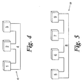
- a microfluidic system is designated generally by the reference numeral 40.
- the system is particularly appropriate for use with an external pump.
- the system 40 comprises a measurement apparatus 1 and a pump 2, which in this example is an external gas pressure pump.
- the measuring device 1 and the pump 2 are interconnected by a fluidic channel 4.
- the system 40 further comprises a membrane 3 in accordance with the present invention.
- the presence of the membrane 3 means that liquid can be introduced through the membrane 3, but at the completion of the priming process, the membrane 3 will seal off the inlet of the system. This is necessary to ensure a correct operation of the pump, which would otherwise be short circuited.
- the air flow resistance of the pump 2 and the measurement apparatus 1 is large compared with the volume of the interconnecting channel 4, resulting in an excessive time requirement for the priming process.
- a second embodiment of a system according to the present invention is designated generally in Figure 5 by the reference numeral 50.
- the system 50 comprises a membrane 5 for introducing liquid into the system 50.
- the system 50 further comprises a pump 6, for example an electroosmotic pumping device, and a measurement apparatus 7 connected to the pump 6 by means of an interconnecting channel 8.
- the system 50 further comprises a second membrane 9 in accordance with the present invention which serves as an outlet for air contained within the system 50, allowing air to vent from the system.
- the two membranes 5, 9 will seal the system 50 enabling the micropump 6 to exert pressure on the measurement system.
- a membrane according to the present invention is designated generally by the reference numeral 10.
- the membrane 10 comprises an array of penetrating apertures 11.
- the positioning of the apertures in the membrane may be arbitrary, so long as the membrane maintains its mechanical stability. There is therefore, no need to accurately locate the apertures 11 within the membrane 10.
- the membrane thickness is not critical to the functioning of the membrane, but should in general be as small as possible to ensure a low flow resistance through the membrane, whilst at the same time ensuring the mechanical stability and ease of manufacturing.
- the radii of apertures should be chosen so that they fit with the hydrostratic pressures needed in the particular microfluidic system in which the membrane is incorporated.
- Figure 7 shows a membrane 15 according to the present invention embedded into a channel structure with an inlet 14 and an outlet 16.
- Liquid can be introduced into the inlet 14 with an overpressure, which is smaller than the positive holding pressure of the device, forcing the air in front of the liquid out through the membrane apertures.
- the device will seal, enabling pressure driven applications to run without being connected to air volumes, which in some cases can affect the success of the application.
- Figure 8a shows a more complicated fluidic system with an inlet 17, an enclosed volume 18, an outlet 19, a first membrane 20, a second membrane 21, a pumping device 22, and a measurement apparatus or other fluidic system where pumping is required 23.
- a configuration like this is preferred if the physical dimensions of the devices 22 and 23 are so small that surface tension forces and high flow resistance in these makes it troublesome to prime the enclosed volume 18 through these. After priming it is required that the two membranes 20 and 19 enter the sealing states, in order to enable the pump 22 to act on the measurement apparatus 23.
- an amount of liquid should be introduced into the inlet 17 having the same volume as the enclosed volume 18 plus some extra to account for the tolerances in the system, ensuring in all cases sufficient liquid for the priming.
- Gas pressure lower than the positive holding pressure of membrane 20 should be applied to the inlet 17 for a sufficient length of time to allow the liquid to reach the membranes 21, 20.
- a short pressure pulse (0.1-10 seconds) larger than the positive holding pressure of membrane 20 should be applied in order to force liquid through the apertures of the membrane 20.
- a positive pressure lower than the negative holding pressure of membrane 20 should be kept at inlet 17 in order to transfer the liquid into the enclosed volume 18.
- the air in volume 18 will be vented through the second membrane 21. At some point the liquid will reach the second membrane 21 causing it to enter its sealing state.
- FIG 8b another example is shown, where a fluidic system with an inlet 17, an enclosed volume 18, an outlet 19, a membrane 21, a pumping device 24, and a measurement apparatus or other fluidic system where pumping is required 23.
- an amount of liquid should be introduced into the inlet 17, before this is connected to the pumping device.
- the liquid should have the same volume as the enclosed volume 18 plus some extra to account fro the tolerances in the system, ensuring in all cases sufficient liquid for the priming.
- the pumping device should then be connected and gas pressure within the range between the negative and positive holding pressure of membrane 21 can now be exerted on the measurement apparatus 23 by the pumping device.
- the membrane material can, in general, be any hydrophilic material suitable for micropatterning, such as oxidised silicon, silicon nitride, glass, silica, alumina, oxidised aluminium, acrylic.
- the apertures in the membrane can be fabricated using laser milling, micro-drilling, sand blasting, with a high-pressure water jet, with photolithographic techniques, or with other methods for micro-fabrication.
- FIG. 9 A preferred embodiment is shown in Figure 9 where a membrane with holes is defined on a silicon substrate using standard MEMS technology (See reference 2).
- the structure consists of a silicon substrate 46, a membrane 25, and pores defined lithographically and etched into the membrane 26. This can for example be done through the following process:
- the substrate can be fabricated through the following process:
- the substrate can be fabricated through the following process:
- the substrate can be fabricated through the following process:
- the substrate can be fabricated through the following process:
- the substrate can be fabricated through the following process:
- the substrate can be fabricated through the following process:
- the substrate can be fabricated through the following process:
- the substrate can be fabricated through the following process:
- a membrane can be defined in silicon nitride alone using a similar process.
- the main advantage of fabricating the present invention using the above mentioned silicon technology is that it makes it possible to integrate it with silicon microfluidics systems.
- the invention can be integrated into a silicon-based device for doing electrophysiology measurements, with the purpose of easing the priming process.
- a description of a device which consists of an aperture for obtaining a high resistance seal to a cell, and an electroosmotic flow pump which is used to apply suction to the aperture with the purpose of trapping and manipulating the cell.
- the aperture can be defined in a silicon membrane in the same manner as the present invention.
- an electroosmotic pumping device based on silicon technology is disclosed. This device can be fabricated as an array of apertures in a silicon membrane in the same manner as the present invention.
- Figure 10 shows an integration of an aperture for carrying out electrophysiology measurements, an electroosmotic flow pump, and two systems according to the present invention, monolithically integrated on a silicon chip 27.
- This chip system is an embodiment of the system shown in Fig. 9.
- the bottom side of the silicon is sealed off using a channel defining layer 28 and a bottom plate containing an electrochemical electrode 29.
- the pieces 28 and 29 could alternatively be made in one piece.
- the pieces 27, 28, and 29 could be bonded or glued on wafer scale or on a single die level.
- the enclosed volume 60 should be filled with liquid; a priming inlet formed from membrane 31; and a venting outlet formed from membrane 37 should be sealed off.
- Membrane 31 has an inlet channel 62 where liquid is initially introduced.
- the apertures of membrane 31 have a radius of 1.5-4 ⁇ m.
- the membrane could optionally be coated with a hydrophobic material.
- the electroosmotic flow pump 33 has a topside fluidic system 64 containing a liquid inlet and an electrochemical electrode.
- the apertures of pump 33 have a radius of 0.2-0.7 ⁇ m.
- the aperture for carrying out electrophysiology measurements 35 consists of a single aperture with a radius of 0.3-1.0 ⁇ m in a membrane.
- a fluidics system 36 exists containing an inlet for cells and at least one electrochemical electrode.
- the membrane 37 has a venting channel 68 where the air originally contained in the enclosed volume can be expelled.
- the sieve apertures of membrane 37 have a radius of 1.5-4 ⁇ m.
- the membrane could optionally be coated with a hydrophobic material.
- Membranes 31, 37, pump 33 and the membrane defining aperture 35 can be made with the same membrane thickness of 1-50 ⁇ m. Electrochemical electrodes 39 and 41 can be included in the enclosed volume 60, and contacted with through-holes in the bottom plate 29 to contact pads 44 and 42.
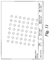
- FIG 11 shows a scanning electron micrograph of a fabricated membrane 110 according to the present invention.
- the membrane has a 14 ⁇ m thick silicon membrane made on a 380 ⁇ m thick Si wafer by means of anisotropic etch.
- the 3.5 ⁇ m radius apertures were etched with Deep Reactive Ion Etch (DRIE).
- DRIE Deep Reactive Ion Etch
- the silicon surfaces including the interior of the holes were coated with a thin layer of silicon oxide (quartz).
- the devices were packaged in plastic housings with fluidic channels on the top and bottom side, in a configuration as shown in Figure 7.
- the devices were tested by adding 20 ⁇ l of water with a small amount of malachite green dye to the channel on the topside of the device.
- a gas pressure of +50 mbar was then applied for 10s in order to fill the channel until the liquid reached the membrane.
- Increasing suction or pressure was applied in periods of either 30 or 60s.
- a microscope was used to monitor breaches of the sealing state. After a breach the highest pressure/suction used was noted, and the second highest pressure/suction used was noted as the apparent lower limit of that particular device.
Landscapes
- Chemical & Material Sciences (AREA)
- Engineering & Computer Science (AREA)
- General Engineering & Computer Science (AREA)
- Dispersion Chemistry (AREA)
- Health & Medical Sciences (AREA)
- Mechanical Engineering (AREA)
- Hematology (AREA)
- Chemical Kinetics & Catalysis (AREA)
- Clinical Laboratory Science (AREA)
- General Health & Medical Sciences (AREA)
- Analytical Chemistry (AREA)
- Apparatus Associated With Microorganisms And Enzymes (AREA)
- Mechanical Coupling Of Light Guides (AREA)
- Materials For Medical Uses (AREA)
- Investigating Or Analyzing Materials By The Use Of Electric Means (AREA)
- Automatic Analysis And Handling Materials Therefor (AREA)
- Conductive Materials (AREA)
- Absorbent Articles And Supports Therefor (AREA)
- Micromachines (AREA)
- Undergarments, Swaddling Clothes, Handkerchiefs Or Underwear Materials (AREA)
- Orthopedics, Nursing, And Contraception (AREA)
Claims (19)
- Système microfluidique pour déterminer et/ou surveiller des propriétés électrophysiologiques de canaux ioniques, dans des structures contenant des canaux ioniques, comprenant :un canal comprenant un orifice d'entrée (62) et un orifice de sortie (68) ;une première membrane (37) positionnée entre l'orifice d'entrée (62) et l'orifice de sortie (68) et comprenant une ouverture ayant un rayon qui se situe dans la plage de 0,1 à 50 µm, l'orifice d'entrée et l'orifice de sortie étant en communication hydraulique l'un avec l'autre de telle sorte qu'un fluide peut circuler le long du canal entre l'orifice d'entrée (62) et l'orifice de sortie (68) ;des moyens de pression (33) pour créer une différence de pression entre l'orifice d'entrée (62) et l'orifice de sortie (68), moyennant quoi, en fonctionnement, le mouvement d'un fluide à l'intérieur du canal est arrêté au niveau de la première membrane (37) sous l'action d'une tension de surface créée dans le fluide au niveau de l'ouverture, jusqu'à ce que les moyens de pression créent une différence de pression entre l'orifice d'entrée (62) et l'orifice de sortie (68) qui dépasse la tension de surface créée au niveau de l'ouverture.
- Système selon la revendication 1 dans lequel la première membrane (37) comprend une pluralité d'ouvertures, chacune de ces ouvertures ayant un rayon qui se situe dans une plage de 0,1 à 50 µm.
- Système selon l'une quelconque des revendications précédentes dans lequel les moyens de pression (33) comprennent un dispositif de pompage, le système comprenant en outre un premier volume formé (60) positionné entre l'orifice d'entrée (62) et l'orifice de sortie (68), un deuxième volume (64) en communication hydraulique avec le premier volume (60), le dispositif de pompage (33) étant en communication hydraulique avec les premier et deuxième volumes (60, 64), pour pomper un fluide à travers le système ou pour exercer une différence de pression hydraulique entre les premier et deuxième volumes (60, 64), la première membrane (37) étant positionnée entre l'orifice de sortie (68) et le premier volume (60).
- Système selon la revendication 3 comprenant en outre une deuxième membrane (31) comprenant une ouverture ayant un rayon qui se situe dans la plage de 0,1 à 50 µm, et étant positionnée entre l'orifice d'entrée (62) et le premier volume (60).
- Système selon la revendication 3 ou 4 comprenant une pluralité de deuxièmes volumes (64, 66).
- Système selon l'une quelconque des revendications 3, 4 ou 5, dans lequel le ou chacun des deuxièmes volumes (64, 66) comprend un deuxième orifice d'entrée.
- Système selon l'une quelconque des revendications 3, 4, 5 ou 6, dans lequel le ou chacun des deuxièmes volumes (64, 66) comprend un deuxième orifice de sortie.
- Système selon la revendication 4, ou selon l'une quelconque des revendications qui dépendent de celle-ci, dans lequel la deuxième membrane (31) comprend une pluralité d'ouvertures, chacune de ces ouvertures ayant un rayon qui se situe dans la plage de 0,1 à 50 µm.
- Système selon l'une quelconque des revendications précédentes dans lequel la ou chacune des membranes (31, 37) comprend un matériau hydrophile.
- Système selon la revendication 8 dans lequel la ou chacune des membranes (31, 37) est formée à partir de silicium oxydé, de nitrure de silicium, de verre, de silice, d'alumine, d'aluminium oxydé, ou d'acrylique.
- Système selon la revendication 8 dans lequel le système est formé à partir de silicium.
- Système selon l'une quelconque des revendications précédentes dans lequel la ou chacune des membranes (31, 37) est enduite d'un matériau hydrophobe sur au moins une face.
- Système selon la revendication 12 dans lequel le matériau hydrophile comprend du PTFE ou du PDMS.
- Système selon l'une quelconque des revendications précédentes dans lequel l'épaisseur de la ou de chacune des membranes (31, 37) se situe dans la plage de 50 à 400 nm quand la membrane (31, 37) est formée à partir de nitrure de silicium ; dans la plage de 1 à 20 µm quand la membrane (31, 37) est formée à partir de silicium oxydé ; dans la plage de 2 à 200 µm quand la membrane (31, 37) est formée à partir de verre ou de silice ; et dans la plage de 5 à 500 µm quand la membrane est formée à partir d'alumine ou d'une matière plastique.
- Utilisation d'une membrane comprenant une ouverture ayant un rayon qui se situe dans la plage de 0,1 à 50 µm, dans un système microfluidique selon l'une quelconque des revendications 1 à 14.
- Dispositif de prise de mesures électrophysiologiques comprenant un système selon l'une quelconque des revendications 1 à 14.
- Procédé d'amorçage d'un système selon l'une quelconque des revendications 1 à 14 comprenant l'étape consistant à remplacer de l'air initialement présent dans le système par un liquide.
- Procédé selon la revendication 17 dans lequel l'étape consistant à remplacer de l'air initialement présent dans le système par un liquide est contrôlée de manière externe au moyen d'une pression de gaz.
- Procédé selon la revendication 19 dans lequel la pression de gaz est appliquée par impulsions d'une durée de 0,1 à 10 secondes.
Applications Claiming Priority (3)
| Application Number | Priority Date | Filing Date | Title |
|---|---|---|---|
| GBGB0303920.3A GB0303920D0 (en) | 2003-02-21 | 2003-02-21 | Capillary stop |
| GB0303920 | 2003-02-21 | ||
| PCT/IB2004/001031 WO2004074829A1 (fr) | 2003-02-21 | 2004-02-23 | Dispositif d'arret capillaire |
Publications (2)
| Publication Number | Publication Date |
|---|---|
| EP1597576A1 EP1597576A1 (fr) | 2005-11-23 |
| EP1597576B1 true EP1597576B1 (fr) | 2007-04-04 |
Family
ID=9953377
Family Applications (1)
| Application Number | Title | Priority Date | Filing Date |
|---|---|---|---|
| EP04713620A Expired - Lifetime EP1597576B1 (fr) | 2003-02-21 | 2004-02-23 | Dispositif d'arret capillaire |
Country Status (10)
| Country | Link |
|---|---|
| US (1) | US8268260B2 (fr) |
| EP (1) | EP1597576B1 (fr) |
| JP (1) | JP2006518851A (fr) |
| CN (1) | CN1774629B (fr) |
| AT (1) | ATE358823T1 (fr) |
| CA (1) | CA2516724C (fr) |
| DE (1) | DE602004005681T2 (fr) |
| DK (1) | DK1597576T3 (fr) |
| GB (1) | GB0303920D0 (fr) |
| WO (1) | WO2004074829A1 (fr) |
Cited By (2)
| Publication number | Priority date | Publication date | Assignee | Title |
|---|---|---|---|---|
| US8058056B2 (en) | 2004-03-12 | 2011-11-15 | The Regents Of The University Of California | Method and apparatus for integrated cell handling and measurements |
| US10167502B2 (en) | 2015-04-03 | 2019-01-01 | Fluxion Biosciences, Inc. | Molecular characterization of single cells and cell populations for non-invasive diagnostics |
Families Citing this family (12)
| Publication number | Priority date | Publication date | Assignee | Title |
|---|---|---|---|---|
| US20020144905A1 (en) | 1997-12-17 | 2002-10-10 | Christian Schmidt | Sample positioning and analysis system |
| US7244349B2 (en) | 1997-12-17 | 2007-07-17 | Molecular Devices Corporation | Multiaperture sample positioning and analysis system |
| US7270730B2 (en) | 2000-08-04 | 2007-09-18 | Essen Instruments, Inc. | High-throughput electrophysiological measurement system |
| US7067046B2 (en) | 2000-08-04 | 2006-06-27 | Essen Instruments, Inc. | System for rapid chemical activation in high-throughput electrophysiological measurements |
| JP2009518643A (ja) * | 2005-12-12 | 2009-05-07 | コーニンクレッカ フィリップス エレクトロニクス エヌ ヴィ | クロマトグラフィで使用する分離媒体 |
| US8293524B2 (en) | 2006-03-31 | 2012-10-23 | Fluxion Biosciences Inc. | Methods and apparatus for the manipulation of particle suspensions and testing thereof |
| DE502008001596D1 (de) * | 2008-06-02 | 2010-12-02 | Boehringer Ingelheim Micropart | Mikrofluidische Folienstruktur zum Dosierren von Flüssigkeiten |
| CN102200536B (zh) | 2010-03-25 | 2015-05-27 | 艾博生物医药(杭州)有限公司 | 测试液体样本中被分析物的检测装置 |
| US8702930B2 (en) | 2011-01-13 | 2014-04-22 | Panasonic Corporation | Sensor chip and storage method thereof |
| US10830758B2 (en) * | 2015-08-09 | 2020-11-10 | Georgia Tech Research Corporation | Systems and methods enabling patch-clamp re-use |
| EP4460694A1 (fr) | 2022-01-07 | 2024-11-13 | Sophion Bioscience A/S | Guidage de pipette dans un patch-clamp à plaques à cupules multiples |
| WO2023131698A1 (fr) | 2022-01-07 | 2023-07-13 | Sophion Bioscience A/S | Appareil de patch-clamp semi-automatisé et procédé de réalisation d'une procédure de patch-clamp |
Family Cites Families (13)
| Publication number | Priority date | Publication date | Assignee | Title |
|---|---|---|---|---|
| US5368729A (en) * | 1993-07-23 | 1994-11-29 | Whatman, Inc. | Solid phase extraction device |
| DE4405026A1 (de) * | 1994-02-17 | 1995-08-24 | Rossendorf Forschzent | Mikro-Fluidmanipulator |
| US20020144905A1 (en) * | 1997-12-17 | 2002-10-10 | Christian Schmidt | Sample positioning and analysis system |
| ATE317545T1 (de) * | 1999-10-01 | 2006-02-15 | Sophion Bioscience As | Anordnung und verfahren zum feststellen und/oder überwachen elektrophysiologischer eigenschaften von ionenkanälen |
| US6932893B2 (en) * | 2000-10-02 | 2005-08-23 | Sophion Bioscience A/S | System for electrophysiological measurements |
| WO2002029402A2 (fr) | 2000-10-02 | 2002-04-11 | Sophion Bioscience A/S | Systeme permettant de proceder a des mesures electrophysiologiques |
| EP1331997B1 (fr) | 2000-11-06 | 2004-06-16 | Nanostream, Inc. | Regulateurs de debits microfluidiques |
| AU2002248149A1 (en) * | 2000-11-16 | 2002-08-12 | Fluidigm Corporation | Microfluidic devices for introducing and dispensing fluids from microfluidic systems |
| JP3738899B2 (ja) * | 2000-12-07 | 2006-01-25 | 株式会社 エフェクター細胞研究所 | 微量試料処理装置 |
| JP2002218974A (ja) | 2001-01-24 | 2002-08-06 | Ebara Corp | 反応プローブチップ及び検出システム |
| US20020117515A1 (en) * | 2001-02-27 | 2002-08-29 | Chih-Ming Lee | Syringe with disposable needle |
| US6588613B1 (en) * | 2002-05-13 | 2003-07-08 | The United States Of America As Represented By The Secretary Of The Air Force | Baby-feeding nipple |
| US6957744B2 (en) * | 2003-01-24 | 2005-10-25 | Insta-Mix, Inc. | Nipple with multiple pinholes for baby bottle assembly |
-
2003
- 2003-02-21 GB GBGB0303920.3A patent/GB0303920D0/en not_active Ceased
-
2004
- 2004-02-23 US US10/546,457 patent/US8268260B2/en active Active
- 2004-02-23 WO PCT/IB2004/001031 patent/WO2004074829A1/fr not_active Ceased
- 2004-02-23 EP EP04713620A patent/EP1597576B1/fr not_active Expired - Lifetime
- 2004-02-23 DK DK04713620T patent/DK1597576T3/da active
- 2004-02-23 AT AT04713620T patent/ATE358823T1/de not_active IP Right Cessation
- 2004-02-23 JP JP2006502503A patent/JP2006518851A/ja active Pending
- 2004-02-23 CN CN200480009952.4A patent/CN1774629B/zh not_active Expired - Lifetime
- 2004-02-23 DE DE602004005681T patent/DE602004005681T2/de not_active Expired - Lifetime
- 2004-02-23 CA CA2516724A patent/CA2516724C/fr not_active Expired - Fee Related
Cited By (3)
| Publication number | Priority date | Publication date | Assignee | Title |
|---|---|---|---|---|
| US8058056B2 (en) | 2004-03-12 | 2011-11-15 | The Regents Of The University Of California | Method and apparatus for integrated cell handling and measurements |
| US10167502B2 (en) | 2015-04-03 | 2019-01-01 | Fluxion Biosciences, Inc. | Molecular characterization of single cells and cell populations for non-invasive diagnostics |
| US11098352B2 (en) | 2015-04-03 | 2021-08-24 | Fluxion Biosciences, Inc. | Molecular characterization of single cells and cell populations for non-invasive diagnostics |
Also Published As
| Publication number | Publication date |
|---|---|
| CN1774629B (zh) | 2011-04-13 |
| CA2516724C (fr) | 2014-09-02 |
| EP1597576A1 (fr) | 2005-11-23 |
| US20060251544A1 (en) | 2006-11-09 |
| CN1774629A (zh) | 2006-05-17 |
| CA2516724A1 (fr) | 2004-09-02 |
| ATE358823T1 (de) | 2007-04-15 |
| US8268260B2 (en) | 2012-09-18 |
| GB0303920D0 (en) | 2003-03-26 |
| JP2006518851A (ja) | 2006-08-17 |
| WO2004074829A1 (fr) | 2004-09-02 |
| DK1597576T3 (da) | 2007-08-06 |
| DE602004005681T2 (de) | 2007-12-27 |
| DE602004005681D1 (de) | 2007-05-16 |
Similar Documents
| Publication | Publication Date | Title |
|---|---|---|
| EP1597576B1 (fr) | Dispositif d'arret capillaire | |
| US8349158B2 (en) | Electrowetting pumping device and application to electric activity measurements | |
| EP1712909B1 (fr) | Methode permettant de former une membrane lipidique double plane a des fins d'analyse proteique membranaire | |
| US6951632B2 (en) | Microfluidic devices for introducing and dispensing fluids from microfluidic systems | |
| US20020148992A1 (en) | Pneumatic valve interface for use in microfluidic structures | |
| US9364795B2 (en) | Nano and microfluidic device for separating and concentrating particles present in a fluid | |
| US20030104512A1 (en) | Biosensors for single cell and multi cell analysis | |
| US20040094733A1 (en) | Micro-fluidic system | |
| US20100015008A1 (en) | Microfluidic device for analyzing the status of a particle | |
| EP1495105B1 (fr) | Substrat et procede de mesure des proprietes electrophysiologiques de membranes cellulaires | |
| CA2434214A1 (fr) | Dispositif et procede d'analyse de canaux ioniques dans des membranes | |
| US20100055673A1 (en) | Transparent microfluidic device | |
| CA2420682A1 (fr) | Systeme microfluidique | |
| US7288785B2 (en) | Substrate and method for measuring the electro-physiological properties of cell membranes | |
| Agarwal et al. | Self-sealed circular channels for micro-fluidics | |
| JP2014030382A (ja) | マイクロ流体デバイス及び脂質二重膜の形成方法 | |
| Suzuki et al. | Planar lipid membrane array for membrane protein chip | |
| Lehnert et al. | Patch-Clamp Microsystems: A revolution in electrophysiology? | |
| Alberti et al. | Cell trapping platform towards a patch-clamp microchannel array | |
| Seo | Soft-state integrated microfluidic patch-clamp array chip |
Legal Events
| Date | Code | Title | Description |
|---|---|---|---|
| PUAI | Public reference made under article 153(3) epc to a published international application that has entered the european phase |
Free format text: ORIGINAL CODE: 0009012 |
|
| 17P | Request for examination filed |
Effective date: 20050915 |
|
| AK | Designated contracting states |
Kind code of ref document: A1 Designated state(s): AT BE BG CH CY CZ DE DK EE ES FI FR GB GR HU IE IT LI LU MC NL PT RO SE SI SK TR |
|
| AX | Request for extension of the european patent |
Extension state: AL LT LV MK |
|
| DAX | Request for extension of the european patent (deleted) | ||
| GRAP | Despatch of communication of intention to grant a patent |
Free format text: ORIGINAL CODE: EPIDOSNIGR1 |
|
| RAP1 | Party data changed (applicant data changed or rights of an application transferred) |
Owner name: SOPHION BIOSCIENCE A/S |
|
| GRAS | Grant fee paid |
Free format text: ORIGINAL CODE: EPIDOSNIGR3 |
|
| GRAA | (expected) grant |
Free format text: ORIGINAL CODE: 0009210 |
|
| AK | Designated contracting states |
Kind code of ref document: B1 Designated state(s): AT BE BG CH CY CZ DE DK EE ES FI FR GB GR HU IE IT LI LU MC NL PT RO SE SI SK TR |
|
| PG25 | Lapsed in a contracting state [announced via postgrant information from national office to epo] |
Ref country code: FI Free format text: LAPSE BECAUSE OF FAILURE TO SUBMIT A TRANSLATION OF THE DESCRIPTION OR TO PAY THE FEE WITHIN THE PRESCRIBED TIME-LIMIT Effective date: 20070404 Ref country code: SI Free format text: LAPSE BECAUSE OF FAILURE TO SUBMIT A TRANSLATION OF THE DESCRIPTION OR TO PAY THE FEE WITHIN THE PRESCRIBED TIME-LIMIT Effective date: 20070404 |
|
| REG | Reference to a national code |
Ref country code: GB Ref legal event code: FG4D |
|
| REG | Reference to a national code |
Ref country code: CH Ref legal event code: EP |
|
| REF | Corresponds to: |
Ref document number: 602004005681 Country of ref document: DE Date of ref document: 20070516 Kind code of ref document: P |
|
| REG | Reference to a national code |
Ref country code: IE Ref legal event code: FG4D |
|
| PG25 | Lapsed in a contracting state [announced via postgrant information from national office to epo] |
Ref country code: SE Free format text: LAPSE BECAUSE OF FAILURE TO SUBMIT A TRANSLATION OF THE DESCRIPTION OR TO PAY THE FEE WITHIN THE PRESCRIBED TIME-LIMIT Effective date: 20070704 |
|
| PG25 | Lapsed in a contracting state [announced via postgrant information from national office to epo] |
Ref country code: ES Free format text: LAPSE BECAUSE OF FAILURE TO SUBMIT A TRANSLATION OF THE DESCRIPTION OR TO PAY THE FEE WITHIN THE PRESCRIBED TIME-LIMIT Effective date: 20070715 |
|
| REG | Reference to a national code |
Ref country code: CH Ref legal event code: NV Representative=s name: KIRKER & CIE S.A. |
|
| REG | Reference to a national code |
Ref country code: DK Ref legal event code: T3 |
|
| PG25 | Lapsed in a contracting state [announced via postgrant information from national office to epo] |
Ref country code: PT Free format text: LAPSE BECAUSE OF FAILURE TO SUBMIT A TRANSLATION OF THE DESCRIPTION OR TO PAY THE FEE WITHIN THE PRESCRIBED TIME-LIMIT Effective date: 20070904 |
|
| ET | Fr: translation filed | ||
| NLV1 | Nl: lapsed or annulled due to failure to fulfill the requirements of art. 29p and 29m of the patents act | ||
| PG25 | Lapsed in a contracting state [announced via postgrant information from national office to epo] |
Ref country code: AT Free format text: LAPSE BECAUSE OF FAILURE TO SUBMIT A TRANSLATION OF THE DESCRIPTION OR TO PAY THE FEE WITHIN THE PRESCRIBED TIME-LIMIT Effective date: 20070404 |
|
| PG25 | Lapsed in a contracting state [announced via postgrant information from national office to epo] |
Ref country code: BE Free format text: LAPSE BECAUSE OF FAILURE TO SUBMIT A TRANSLATION OF THE DESCRIPTION OR TO PAY THE FEE WITHIN THE PRESCRIBED TIME-LIMIT Effective date: 20070404 |
|
| PG25 | Lapsed in a contracting state [announced via postgrant information from national office to epo] |
Ref country code: CZ Free format text: LAPSE BECAUSE OF FAILURE TO SUBMIT A TRANSLATION OF THE DESCRIPTION OR TO PAY THE FEE WITHIN THE PRESCRIBED TIME-LIMIT Effective date: 20070404 Ref country code: NL Free format text: LAPSE BECAUSE OF FAILURE TO SUBMIT A TRANSLATION OF THE DESCRIPTION OR TO PAY THE FEE WITHIN THE PRESCRIBED TIME-LIMIT Effective date: 20070404 Ref country code: BG Free format text: LAPSE BECAUSE OF FAILURE TO SUBMIT A TRANSLATION OF THE DESCRIPTION OR TO PAY THE FEE WITHIN THE PRESCRIBED TIME-LIMIT Effective date: 20070704 |
|
| PLBE | No opposition filed within time limit |
Free format text: ORIGINAL CODE: 0009261 |
|
| STAA | Information on the status of an ep patent application or granted ep patent |
Free format text: STATUS: NO OPPOSITION FILED WITHIN TIME LIMIT |
|
| PG25 | Lapsed in a contracting state [announced via postgrant information from national office to epo] |
Ref country code: SK Free format text: LAPSE BECAUSE OF FAILURE TO SUBMIT A TRANSLATION OF THE DESCRIPTION OR TO PAY THE FEE WITHIN THE PRESCRIBED TIME-LIMIT Effective date: 20070404 |
|
| 26N | No opposition filed |
Effective date: 20080107 |
|
| PG25 | Lapsed in a contracting state [announced via postgrant information from national office to epo] |
Ref country code: IT Free format text: LAPSE BECAUSE OF FAILURE TO SUBMIT A TRANSLATION OF THE DESCRIPTION OR TO PAY THE FEE WITHIN THE PRESCRIBED TIME-LIMIT Effective date: 20070404 Ref country code: GR Free format text: LAPSE BECAUSE OF FAILURE TO SUBMIT A TRANSLATION OF THE DESCRIPTION OR TO PAY THE FEE WITHIN THE PRESCRIBED TIME-LIMIT Effective date: 20070705 |
|
| PG25 | Lapsed in a contracting state [announced via postgrant information from national office to epo] |
Ref country code: RO Free format text: LAPSE BECAUSE OF FAILURE TO SUBMIT A TRANSLATION OF THE DESCRIPTION OR TO PAY THE FEE WITHIN THE PRESCRIBED TIME-LIMIT Effective date: 20070404 |
|
| PG25 | Lapsed in a contracting state [announced via postgrant information from national office to epo] |
Ref country code: MC Free format text: LAPSE BECAUSE OF NON-PAYMENT OF DUE FEES Effective date: 20080228 |
|
| PG25 | Lapsed in a contracting state [announced via postgrant information from national office to epo] |
Ref country code: IE Free format text: LAPSE BECAUSE OF NON-PAYMENT OF DUE FEES Effective date: 20080225 Ref country code: EE Free format text: LAPSE BECAUSE OF FAILURE TO SUBMIT A TRANSLATION OF THE DESCRIPTION OR TO PAY THE FEE WITHIN THE PRESCRIBED TIME-LIMIT Effective date: 20070404 |
|
| PG25 | Lapsed in a contracting state [announced via postgrant information from national office to epo] |
Ref country code: CY Free format text: LAPSE BECAUSE OF FAILURE TO SUBMIT A TRANSLATION OF THE DESCRIPTION OR TO PAY THE FEE WITHIN THE PRESCRIBED TIME-LIMIT Effective date: 20070404 |
|
| PG25 | Lapsed in a contracting state [announced via postgrant information from national office to epo] |
Ref country code: HU Free format text: LAPSE BECAUSE OF FAILURE TO SUBMIT A TRANSLATION OF THE DESCRIPTION OR TO PAY THE FEE WITHIN THE PRESCRIBED TIME-LIMIT Effective date: 20071005 Ref country code: LU Free format text: LAPSE BECAUSE OF NON-PAYMENT OF DUE FEES Effective date: 20080223 |
|
| PG25 | Lapsed in a contracting state [announced via postgrant information from national office to epo] |
Ref country code: TR Free format text: LAPSE BECAUSE OF FAILURE TO SUBMIT A TRANSLATION OF THE DESCRIPTION OR TO PAY THE FEE WITHIN THE PRESCRIBED TIME-LIMIT Effective date: 20070404 |
|
| REG | Reference to a national code |
Ref country code: FR Ref legal event code: PLFP Year of fee payment: 13 |
|
| REG | Reference to a national code |
Ref country code: FR Ref legal event code: PLFP Year of fee payment: 14 |
|
| REG | Reference to a national code |
Ref country code: FR Ref legal event code: PLFP Year of fee payment: 15 |
|
| PGFP | Annual fee paid to national office [announced via postgrant information from national office to epo] |
Ref country code: FR Payment date: 20230209 Year of fee payment: 20 Ref country code: DK Payment date: 20230119 Year of fee payment: 20 Ref country code: CH Payment date: 20230307 Year of fee payment: 20 |
|
| PGFP | Annual fee paid to national office [announced via postgrant information from national office to epo] |
Ref country code: GB Payment date: 20230209 Year of fee payment: 20 Ref country code: DE Payment date: 20230119 Year of fee payment: 20 |
|
| REG | Reference to a national code |
Ref country code: DE Ref legal event code: R071 Ref document number: 602004005681 Country of ref document: DE |
|
| REG | Reference to a national code |
Ref country code: DK Ref legal event code: EUP Expiry date: 20240223 |
|
| REG | Reference to a national code |
Ref country code: CH Ref legal event code: PL |
|
| REG | Reference to a national code |
Ref country code: GB Ref legal event code: PE20 Expiry date: 20240222 |
|
| PG25 | Lapsed in a contracting state [announced via postgrant information from national office to epo] |
Ref country code: GB Free format text: LAPSE BECAUSE OF EXPIRATION OF PROTECTION Effective date: 20240222 |