EP1598092A2 - Management du chargement d'une batterie pour un dispositif implantable - Google Patents
Management du chargement d'une batterie pour un dispositif implantable Download PDFInfo
- Publication number
- EP1598092A2 EP1598092A2 EP05016794A EP05016794A EP1598092A2 EP 1598092 A2 EP1598092 A2 EP 1598092A2 EP 05016794 A EP05016794 A EP 05016794A EP 05016794 A EP05016794 A EP 05016794A EP 1598092 A2 EP1598092 A2 EP 1598092A2
- Authority
- EP
- European Patent Office
- Prior art keywords
- recharge
- power source
- energy
- medical device
- management system
- Prior art date
- Legal status (The legal status is an assumption and is not a legal conclusion. Google has not performed a legal analysis and makes no representation as to the accuracy of the status listed.)
- Granted
Links
Images



Classifications
-
- A—HUMAN NECESSITIES
- A61—MEDICAL OR VETERINARY SCIENCE; HYGIENE
- A61N—ELECTROTHERAPY; MAGNETOTHERAPY; RADIATION THERAPY; ULTRASOUND THERAPY
- A61N1/00—Electrotherapy; Circuits therefor
- A61N1/18—Applying electric currents by contact electrodes
- A61N1/32—Applying electric currents by contact electrodes alternating or intermittent currents
- A61N1/36—Applying electric currents by contact electrodes alternating or intermittent currents for stimulation
- A61N1/372—Arrangements in connection with the implantation of stimulators
- A61N1/378—Electrical supply
- A61N1/3787—Electrical supply from an external energy source
-
- A—HUMAN NECESSITIES
- A61—MEDICAL OR VETERINARY SCIENCE; HYGIENE
- A61N—ELECTROTHERAPY; MAGNETOTHERAPY; RADIATION THERAPY; ULTRASOUND THERAPY
- A61N1/00—Electrotherapy; Circuits therefor
- A61N1/18—Applying electric currents by contact electrodes
- A61N1/32—Applying electric currents by contact electrodes alternating or intermittent currents
- A61N1/36—Applying electric currents by contact electrodes alternating or intermittent currents for stimulation
- A61N1/3605—Implantable neurostimulators for stimulating central or peripheral nerve system
- A61N1/36128—Control systems
- A61N1/36142—Control systems for improving safety
Definitions
- This invention relates generally to implantable medical devices, and more particularly to a battery recharge management system for implantable medical devices.
- medical devices can be surgically implanted or connected externally to the patient receiving treatment. Physicians use medical devices alone or in combination with drug therapies to treat patient medical conditions. For some medical conditions, medical devices provide the best, and sometimes the only, therapy to restore an individual to a more healthful condition and a fuller life.
- Implantable medical devices are commonly used today to treat patients suffering from various ailments. Implantable medical devices can be used to treat any number of conditions such as pain, incontinence, movement disorders such as epilepsy and Parkinson's disease, and sleep apnea. Additional therapies appear promising to treat a variety of physiological, psychological, and emotional conditions. As the number of implantable medical device therapies has expanded, greater demands have been placed on the implantable medical device.
- Implantable Neuro Stimulator delivers mild electrical impulses to neural tissue using an electrical lead.
- the neurostimulation targets desired neural tissue to treat the ailment of concern. For example, in the case of pain, electrical impulses (which are felt as tingling) may be directed to cover the specific sites where the patient is feeling pain. Neurostimulation can give patients effective pain relief and can reduce or eliminate the need for repeat surgeries and the need for pain medications.
- Implantable medical devices such as neurostimulation systems may be partially implantable where a battery source is worn outside the patient's body. This system requires a coil and/or an antenna to be placed on the patient's skin over the site of the receiver to provide energy and/or control to the implanted device.
- the medical device is totally implantable where the battery is part of the implanted device. The physician and patient may control the implanted system using an external programmer.
- totally implantable systems include, for example, the Itrel® 3 brand neurostimulator sold by Medtronic, Inc. of Minneapolis, Minnesota.
- the system generally includes an implantable neurostimulator (INS) (also known as an implantable pulse generator (IPG)), external programmer(s), and electrical lead(s).
- INS implantable neurostimulator
- IPG implantable pulse generator
- the INS is typically implanted near the abdomen of the patient.
- the lead is a small medical wire with special insulation. It is implanted next to the spinal cord through a needle and contains a set of electrodes (small electrical contacts) through which electrical stimulation is delivered to the spinal cord.
- the lead is coupled to the INS via an implanted extension cable.
- the INS can be powered by an internal source such as a battery or by an external source such as a radio frequency transmitter.
- the INS contains electronics to send precise, electrical pulses to the spinal cord, brain, or neural tissue to provide the desired treatment therapy.
- the external programmer is a hand-held device that allows the physician or patient to optimize the stimulation therapy delivered by the INS.
- the external programmer communicates with the INS using radio waves.
- An alternative such rechargeable power source is a rechargeable battery, such as a lithium ion battery.
- the rechargeable battery provides a number of advantages over the capacitive power source including (1) less frequent replenishment; and (2) a smaller size and weight. Each of these advantages improves the quality of life of the patient.
- U.S. Patent No. 5,991,665 discloses an energy transfer system for transmitting energy to an implantable medical device.
- the rechargeable battery provides distinct advantages over the capacitive power source, care must be taken in the recharging process so as to maintain the battery's storage capacity and efficacy. For example, recharge of the battery at too high a voltage can damage the battery. Similarly, too high a recharge current can also be harmful to the battery. Damage may also result if the temperature of the INS increases significantly during recharge. Damage to the battery results in reduced efficacy, thereby requiring more frequent recharging, and even eventual replacement of the battery (by surgically explanting the INS). On the one hand, it is undesirable to overheat and damage the battery if it is charged too rapidly. On the other hand, however, it is desirable to charge the battery efficiently to minimize the charging time and improve patient quality of life.
- a recharge management system for an implantable medical device comprising in combination:
- an implantable medical device comprising:
- a recharge management system for an implantable medical device comprising in combination:
- the recharge management system for an implantable medical device has a rechargeable power source such as a lithium ion battery, a recharge coil associated with the implantable device capable of receiving via telemetry magnetic recharge energy from an external device, a recharge regulator receiving the magnetic recharge energy from the recharge coil and providing the recharge energy to the rechargeable power source, a recharge measurement device monitoring at least one recharge parameter, and a recharge regulation control unit for regulating the recharge energy delivered to the power source in response to the recharge measurement device.
- the recharge measurement device measures voltage and current levels being delivered by the external source, voltage and current levels being delivered to the power source, and the energy level of the power source. These measurements are provided to the recharge regulation control unit to adjust the energy provided to the power source to ensure that the power source is being recharged under safe levels.
- the temperature of the implantable medical device is also monitored.
- the recharge management system may further include an overvoltage protection circuit to limit the recharge energy delivered to the recharge regulator from the recharge coil and an AC to DC converter for converting the recharge energy from the recharge coil.
- the present invention provides a recharge management system for an implantable medical device having an outer shield comprising in combination:
- the present invention may be implemented within any number of implantable medical devices that require a self-contained rechargeable power source including, but not limited to, an implantable signal generator, an implantable drug pump, a pacemaker, a defibrillator, a cochlear implant, and an implantable diagnostic device.
- the present invention is a battery recharge management system and method for an implantable medical device.
- the recharge management system regulates the recharge energy that is provided to the battery during recharge by limiting the current into the battery, ensuring against overcharging of the battery, ensuring a minimum and a maximum input voltage during recharge, and ensuring against overheating of the implantable medical device.
- the present invention is implemented within an implantable neurostimulator, however, those skilled in the art will appreciate that the present invention may be implemented generally within any implantable medical device having an implanted rechargeable battery including, but not limited to, implantable drug delivery devices, implantable devices providing stimulation and drug delivery, pacemakers, defibrillators, cochlear implants, and implantable diagnostic devices for detecting bodily conditions of certain organs, like the brain or the heart.
- FIG. 1 shows the general environment of an Implantable Neuro Stimulator (INS) medical device 14 in accordance with a preferred embodiment of the present invention.
- the neurostimulation system generally includes an INS 14, a lead 12, a lead extension 20, an External Neuro Stimulator (ENS) 25, a physician programmer 30, and a patient programmer 35.
- the INS 14 preferably is a modified implantable pulse generator that will be available from Medtronic, Inc. with provisions for multiple pulses occurring either simultaneously or with one pulse shifted in time with respect to the other, and having independently varying amplitudes and pulse widths.
- the INS 14 contains a power source 315 and electronics to send precise, electrical pulses to the spinal cord, brain, or neural tissue to provide the desired treatment therapy.
- INS 14 provides electrical stimulation by way of pulses although other forms of stimulation may be used such as continuous electrical stimulation.
- the lead 12 is a small medical wire with special insulation.
- the lead 12 includes one or more insulated electrical conductors with a connector on the proximal end and electrical contacts on the distal end.
- Some leads are designed to be inserted into a patient percutaneously, such as the Model 3487 A Pisces-Quad® lead available from Medtronic, Inc. of Minneapolis Minnesota, and some leads are designed to be surgically implanted, such as the Model 3998 Specify® lead also available from Medtronic.
- the lead 12 may also be a paddle having a plurality of electrodes including, for example, a Medtronic paddle having model number 3587A.
- the lead 12 may provide electrical stimulation as well as drug infusion.
- Those skilled in the art will appreciate that any variety of leads may be used to practice the present invention.
- the lead 12 is implanted and positioned to stimulate a specific site in the spinal cord or the brain.
- the lead 12 may be positioned along a peripheral nerve or adjacent neural tissue ganglia like the sympathetic chain or it may be positioned to stimulate muscle tissue.
- the lead 12 contains one or more electrodes (small electrical contacts) through which electrical stimulation is delivered from the INS 14 to the targeted neural tissue. If the spinal cord is to be stimulated, the lead 12 may have electrodes that are epidural, intrathecal or placed into the spinal cord itself. Effective spinal cord stimulation may be achieved by any of these lead placements.
- the lead connector can be connected directly to the INS 14, typically the lead connector is connected to a lead extension 20 which can be either temporary for use with an ENS 25 or permanent for use with an INS 14.
- a lead extension 20 is Model 7495 available from Medtronic.
- the ENS 25 functions similarly to the INS 14 but is not designed for implantation.
- the ENS 25 is used to test the efficacy of stimulation therapy for the patient before the INS 14 is surgically implanted.
- An example of an ENS 2 5 is a Model 3625 Screener available from Medtronic.
- the physician programmer 30, also known as a console programmer, uses telemetry to communicate with the implanted INS 14, so a physician can program and manage a patient's therapy stored in the INS 14 and troubleshoot the patient's INS system.
- An example of a physician programmer 30 is a Model 7432 Console Programmer available from Medtronic.
- the patient programmer 35 also uses telemetry to communicate with the INS 14, so the patient can manage some aspects of her therapy as defined by the physician.
- An example of a patient programmer 35 is a Model 7434 Itrel® 3 EZ Patient Programmer available from Medtronic.
- Implantation of an Implantable Neuro Stimulator typically begins with implantation of at least one stimulation lead 12 usually while the patient is under a local anesthetic.
- the lead 12 can either be percutaneously or surgically implanted. Once the lead 12 has been implanted and positioned, the lead's distal end is typically anchored into position to minimize movement of the lead 12 after implantation.
- the lead's proximal end can be configured to connect to a lead extension 20. If a trial screening period is desired, the temporary lead extension 20 can be connected to a percutaneous extension with a proximal end that is external to the body and configured to connect to an External Neuro Stimulator (ENS) 25.
- ENS External Neuro Stimulator
- the ENS 25 is programmed with a therapy and the therapy is often modified to optimize the therapy for the patient.
- the lead's proximal end or the lead extension proximal end is connected to the INS 14.
- the INS 14 is programmed with a therapy and then implanted in the body typically in a subcutaneous pocket at a site selected after considering physician and patient preferences.
- the INS 14 is implanted subcutaneously in a human body and is typically implanted near the abdomen of the patient.
- the above preferred embodiment for the placement of the INS 14 within the lower left abdominal region 6 of the patient is further illustrated in Figure 2C.
- Other preferred embodiments for the placement of stimulator 1 within a human patient is further shown in Figures 2A, 2B, and 2D.
- the INS 14 can be implanted in a pectoral region 4 of the patient.
- the INS 14 can be implanted in a region 5 behind the ear of a patient, and more specifically in the mastoid region.
- the INS 14 can be placed in the lower back or upper buttock region 7 of the patient. The INS 14 is discussed in further detail herein.
- the physician periodically uses the physician programmer 30 to communicate with the implanted INS 14 to manage the patient therapy and collect INS data.
- the patient uses the patient programmer 35 to communicate with the implanted INS 14 to make therapy adjustments that have been programmed by the physician, recharge the INS power source 315, and record diary entries about the effectiveness of the therapy.
- Both the physician programmer 30 and patient programmer 35 have an antenna or coil locator that indicates when the telemetry head is aligned closely enough with the implanted INS 14 for adequate telemetry.
- the neurostimulation system may include a sensor 25 to provide closed-loop feedback control of the INS 14.
- the INS 14 may receive feedback instructions from an external component, which processes a recorded signal from the sensor 25 and sends instruction to signal generator via antenna.
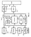
- FIG. 3 is a schematic block diagram of an INS 14 in accordance with a preferred embodiment of the present invention.
- the implantable medical device generally includes a processor 335 with an oscillator 330, a calendar clock 325, memory 340, and system reset 345, a telemetry module 305, a recharge module 310, a power source 315, a power management module 320, a therapy module 350, and a therapy measurement module 355.
- Other components of the INS 14 can include, for example, a diagnostics module (not shown). All components except the power source 315 can be configured on one or more Application Specific Integrated Circuits (ASICs) or may be one or more discrete components, or a combination of both.
- ASICs Application Specific Integrated Circuits
- all components except the oscillator 330, the calendar clock 325, and the power source 315 are connected to bi-direc tional data bus 327 that is non-multiplexed with separate address and data lines.
- the processor 335 is synchronous and operates on low power such as a Motorola 68HC11 synthesized core operating with a compatible instruction set.
- the oscillator 330 operates at a frequency compatible with the processor 335, associated components, and energy constraints such as in the range from 100 KHz to 1.0 MHZ.
- the calendar clock 325 counts the number of seconds since a fixed date for date/time stamping of events and for therapy control such as circadian rhythm linked therapies.
- the memory 340 includes memory sufficient for operation of the INS 14 such as volatile Random Access Memory (RAM) for example Static RAM, nonvolatile Read Only Memory (ROM), Electrically Erasable Programmable Read Only Memory (EEPROM) for example Flash EEPROM, and register arrays configured on ASICs.
- RAM volatile Random Access Memory
- ROM nonvolatile Read Only Memory
- EEPROM Electrically Erasable Programmable Read Only Memory
- register arrays configured on ASICs.
- Direct Memory Access is available to selected modules such as the telemetry module 305, so the telemetry module 305 can request control of the data bus 327 and write data directly to memory 340 bypassing the processor 335.
- the system reset 345 controls operation of ASICs and modules during power-up of the INS 14, so ASICs and modules registers can be loaded and brought on-line in a stable condition.
- the telemetry module 305 provides bi-directional communications between the INS 14 and the external programmers 30 or 35.
- the telemetry module 305 generally comprises a telemetry antenna, a receiver, a transmitter, and a telemetry processor 335.
- Telemetry modules are generally known in the art and are further detailed in U.S. Patent No. 5,752,977, entitled "Efficient High Data Rate Telemetry Format For Implanted Medical Device” issued to Grevious et al. (May 19, 1998).
- the INS 14 may be configured in a variety of versions by removing modules not necessary for the particular configuration and by adding additional components or modules. All components of the INS 14 are contained within or carried on a housing that is hermetically sealed and manufactured from a biocompatible material such as titanium. Feedthroughs provide electrical connectivity through the housing while maintaining a hermetic seal, and the feedthroughs can be filtered to reduce incoming noise from sources such as cell phones.
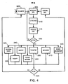
- FIG. 4 depicts a general operation flowchart of the INS 14.
- operation of the INS 14 begins with the processor 335 receiving data from either telemetry module 305 or from an internal source in the INS 14.
- the received data is stored in a memory location.
- the data is processed by the processor 35 to identify the type of data and can include further processing such as validating the integrity of the data.
- a decision is made whether to take an action. If no action is required, the INS 14 stands by to receive data. If an action is required, the action will involve one or more of the following modules or components: calendar clock 325, memory 340, telemetry 305, recharge 310, power management 320, therapy 350, and therapy measurement 355.
- An example of an action would be to recharge the power source 315.
- a decision is made whether the action is to be communicated or "uplinked" to a patient or physician programmer 35 or 30 through the telemetry module 305. If the action is uplinked, the action is recorded in the patient or physician programmer. If the action is not uplinked, the action is recorded internally within the INS 14.
- FIG. 5 is a schematic block diagram of the recharge module 310 of the INS 14 in accordance with a preferred embodiment of the present invention.
- the recharge module 310 provides a form of closed-loop feedback control to ensure proper and efficient charging of the battery with minimized risk of damage to the battery.
- the recharge module 310 serves to regulate the charging rate of the power source 315 according to power source parameters.
- the recharge module 310 also serves to maintain INS 14 temperature within acceptable limits so any temperature rise during recharge does not create an unsafe condition for the patient.
- the INS 14 communicates charging status to the patient charger, so the patient charges at optimum efficiency and at a level that prevents the INS 14 from overheating yet charges the power source 315 efficiently.
- the recharge module 310 generally comprises a recharge coil, an Alternating Current (AC) over-voltage protection device 505, an AC to DC converter 510, a recharge regulator 515, a recharge measurement device 520, and a recharge regulation control unit 525.
- the recharge module 310 charges the battery by receiving an energy transfer signal with a frequency of about 5.0 KHz to 10.0 KHz and converting the energy transfer signal into a regulated DC power to charge the INS power source 315.
- the recharge coil can be the same coil as the telemetry antenna if multiplexed or the recharge coil can be separate from the telemetry antenna.
- the recharge coil may be within the INS 14 housing or may be outside the INS 14 housing but connected through a cable.
- the AC over-voltage protection device 505 can be a Zener diode that shunts high voltage to ground and may be placed at the input or output of the AC to DC converter 510.
- the AC to DC converter 510 can be a standard rectifier circuit or an active rectifier having integrated or discrete component designs.
- the recharge regulator 515 regulates the voltage received from the AC to DC converter 510 to a level appropriate for charging the power source 315.
- the recharge regulation control unit 525 adjusts the recharge regulator 515 in response to information from the recharge measurement device 520 and a recharge program.
- the recharge program is generally within the INS memory 340 and can vary based upon the type of device, type of power source 315, and condition of the power source 315.
- the recharge measurement device 520 measures various recharge parameters of the INS 14 including, but not limited to, the input and output voltage at the recharge regulator 515, the input and output current at the recharge regulator 515, input voltage to the power source, input current to the power source, power source voltage, and power source charge.
- the recharge measurement device 520 also measures temperature of the INS 14.
- temperature of specific areas of the INS 14 may be measured including, but not limited to, the recharge coil, recharge regulator 515, power source 315, and the outer shield for the INS 14. Based upon the recharge measurement, the recharge regulation control unit 525 can increase or decrease the energy reaching the power source 315 (discussed herein).
- the recharge method and apparatus of the present invention supplies a regulated voltage and current to the rechargeable power source 315.
- the regulated voltage and current is continually monitored during recharge.
- the charge current will be controlled to be within the range of 0-100 mA, with capability to achieve 150-200 mA.
- voltage is monitored.
- the charge voltage will be controlled to be in the range of 50 mV - 5.0 V with a maximum being in the range of 6.0 V.
- the current supply is monitored and tapered to prevent the risk of damage to the power source 315.
- the temperature sensing may further limit the charge current threshold in the case of more than a certain rise in temperature in the INS 14.
- the recharge module 310 protects the power source 315 from sudden bursts of energy from an outside source, known or unknown. Even further, the present invention provides for more efficient recharge, namely provides information as to whether recharging energy can be gradually increased to more efficiently re charge the power source 315. Still further, the INS 14 continues to deliver therapy during the recharge process without affecting the stimulation pulse.
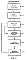
- FIG. 6 is a flow chart depicting the operation of the recharge module 310 in accordance with a preferred embodiment of the present invention.
- This process may be stored as a recharge program that is run by processor 335 and stored in memory 340.
- the recharging process for the INS 14 begins with the patient or the physician, using an external patient programmer 35 or physician programmer 30, placing a telemetry head containing the recharge coil near the INS 14.
- Both the patient and physician programmers 30 and 35 have an antenna or coil locator that indicates when the telemetry head is aligned closely enough with the implanted INS 14 for adequate telemetry and charge coupling.
- a coil (not shown) of the external component creates a magnetic field that a coil of the INS 14 receives.
- the external component also emits command signals to the antenna of the INS 14. These received command signals are demodulated by the telemetry unit 305 and communicated to the processor 335.
- the processor 335 activates the proper control for the inductor to receive the RF coupled energy from the inductor of the external component.
- the magnetic recharge energy may then be delivered from the external programmers 30 or 35 to the INS 14.
- the power source 315 may not have sufficient energy to provide the feedback control.
- the external component may deliver an initial large burst of energy to "wake up" the power source 315 and the recharge module 310. Once the recharge module 310 has energy to implement the closed-loop feedback control, the excess energy may be absorbed away from the power source 315.
- step 610 upon receiving the magnetic recharge energy by the INS 14, it is converted to from AC to DC using the AC/DC converter 510.
- the DC energy is also filtered to smooth out the signal and eliminate noise.
- the DC energy is thereby delivered to the recharge regulator 515.
- the DC signal is regulated by the recharge regulator 515 under control of the recharge regulation control unit 525.
- the recharge regulation control unit 525 receives as input information from the recharge measurement device 520 and program information from the INS processor 335 and memory 340.
- the recharge measurement device 520 provides information to the recharge regulation control unit 525 of vari ous recharge parameters. Based on this information, the recharge regulation control unit 525 adjusts the recharge energy delivered by the recharge regulator 515 to the power source 315.
- the recharge energy is delivered to replenish the power source 315 only if the DC voltage from the AC/DC converter 510 (V in ) reaches a certain minimum.
- the recharge regulator 515 provides recharge energy to the power source 315 in accordance with the parameters provided by the recharge regulation control unit 525.
- the external component initiates the charging process at a safe level.
- the power source charge current or voltage is then slowly increased. The process continues until one of the following three criterion are reached: (1) a lower limit at V in is reached; (2) the power source 315 is replenished to a maximum voltage; (3) the charge current to the power source 315 I in reaches a maximum limit; or (4) the temperature increases more than a preset amount.
- the recharge regulation control unit 525 provides feedback as to whether the power source 315 is receiving the recharge energy and whether the recharge energy is too high or too low. If the recharge energy is too high, the energy can be reduced to reduce risk of damage to the power so urce 315. If the recharge energy is too low, it can be slowly increased to improve recharge efficiency. This can be achieved by adjusting the recharge energy that the recharge regulator 515 provides to the power source 315 and/or by notifying the external component via telemetry signaling to increase or decrease the delivery of magnetic recharge energy.
- the recharge regulation control unit 525 communicates with the external component via telemetry unit 305. Those skilled in the art will appreciate that other communication techniques may be implemented. For example, the recharge regulation control unit 525 communicates with the external component by modulating the load on the recharge coil. This change in the load can then be sensed in the circuitry driving the source coil of the external component.
- the recharge regulation control unit 525 will regulate the current down.
- the INS 14 will inform the charging device that the RF energy being sent is higher than necessary and the charging device will adjust its RF transmission of energy accordingly.
- the INS 14 will communicate to the charging device to lower the supplied energy if components in the INS 14 are heating up above safe limits for the patient and/or device.
- the INS 14 will communicate to the charging device that the RF energy can be increased.
- the recharge measurement unit 520 measures the power source 315 and provides this information to the recharge regulation control unit 525 to control the recharge regulator output energy to an appropriate energy level. Once the power source 315 is fully charged, the recharge regulation control unit 525 instructs the recharge regulator 515 to stop delivery of recharge energy to the power source 315.
- a signal may also be provided via telemetry unit 305 notifying the external device that the power source 315 is fully recharged.
- the processor 335 may be coupled to the charge/discharge monitor.
- the charge/discharge monitor may notify the processor 335 that a "fully charged” state is reached in the rechargeable power source 315.
- the processor 335 may then send a signal via the telemetry unit 305 and onto the external component. Upon receipt of this command signal, the external component may turn off the energy transmitted to the inductor.
- the battery recharge management system of the present invention can be used with any other implantable systems requiring a self-contained rechargeable power source, including, but not limited to, pacemakers, defibrillators, and cochlear implants.
- the battery recharge management system of the present invention may also be used to recharge an implantable diagnostic device for detecting bodily conditions of certain organs, like the brain or the heart.
- the battery recharge management system of the present invention can be used to recharge a drug delivery system having an implantable battery-powered pump.
Landscapes
- Health & Medical Sciences (AREA)
- Engineering & Computer Science (AREA)
- Biomedical Technology (AREA)
- Nuclear Medicine, Radiotherapy & Molecular Imaging (AREA)
- Radiology & Medical Imaging (AREA)
- Life Sciences & Earth Sciences (AREA)
- Animal Behavior & Ethology (AREA)
- General Health & Medical Sciences (AREA)
- Public Health (AREA)
- Veterinary Medicine (AREA)
- Neurology (AREA)
- Neurosurgery (AREA)
- Electrotherapy Devices (AREA)
- Secondary Cells (AREA)
- Infusion, Injection, And Reservoir Apparatuses (AREA)
- Circuits Of Receivers In General (AREA)
Applications Claiming Priority (3)
| Application Number | Priority Date | Filing Date | Title |
|---|---|---|---|
| US562221 | 2000-04-28 | ||
| US09/562,221 US7167756B1 (en) | 2000-04-28 | 2000-04-28 | Battery recharge management for an implantable medical device |
| EP01973774A EP1283732B1 (fr) | 2000-04-28 | 2001-01-18 | Gestion de la recharge d'une batterie d'un dispositif medical implantable |
Related Parent Applications (1)
| Application Number | Title | Priority Date | Filing Date |
|---|---|---|---|
| EP01973774A Division EP1283732B1 (fr) | 2000-04-28 | 2001-01-18 | Gestion de la recharge d'une batterie d'un dispositif medical implantable |
Publications (3)
| Publication Number | Publication Date |
|---|---|
| EP1598092A2 true EP1598092A2 (fr) | 2005-11-23 |
| EP1598092A3 EP1598092A3 (fr) | 2005-12-21 |
| EP1598092B1 EP1598092B1 (fr) | 2008-02-27 |
Family
ID=24245319
Family Applications (2)
| Application Number | Title | Priority Date | Filing Date |
|---|---|---|---|
| EP05016794A Expired - Lifetime EP1598092B1 (fr) | 2000-04-28 | 2001-01-18 | Management du chargement d'une batterie pour un dispositif implantable |
| EP01973774A Expired - Lifetime EP1283732B1 (fr) | 2000-04-28 | 2001-01-18 | Gestion de la recharge d'une batterie d'un dispositif medical implantable |
Family Applications After (1)
| Application Number | Title | Priority Date | Filing Date |
|---|---|---|---|
| EP01973774A Expired - Lifetime EP1283732B1 (fr) | 2000-04-28 | 2001-01-18 | Gestion de la recharge d'une batterie d'un dispositif medical implantable |
Country Status (6)
| Country | Link |
|---|---|
| US (4) | US7167756B1 (fr) |
| EP (2) | EP1598092B1 (fr) |
| JP (1) | JP2003531699A (fr) |
| AT (1) | ATE423596T1 (fr) |
| DE (2) | DE60133054T2 (fr) |
| WO (1) | WO2001083029A1 (fr) |
Cited By (5)
| Publication number | Priority date | Publication date | Assignee | Title |
|---|---|---|---|---|
| WO2007053881A1 (fr) * | 2005-11-08 | 2007-05-18 | Ventrassist Pty Ltd | Ameliorations des systemes de commande et des systemes de puissance destines a des pompes a sang rotatives |
| WO2011059564A1 (fr) * | 2009-11-11 | 2011-05-19 | Boston Scientific Neuromodulation Corporation | Minimisation d'interferences entre des bobines de charge et de telemetrie dans un dispositif medical implantable |
| EP2662114A1 (fr) * | 2009-11-23 | 2013-11-13 | Boston Scientific Neuromodulation Corporation | Chargeur externe efficace destiné à charger une pluralité de dispositifs médicaux implantables |
| US9061159B2 (en) | 2009-11-11 | 2015-06-23 | Boston Scientific Neuromodulation Corporation | Using the case of an implantable medical device to broaden communication bandwidth |
| US9821112B2 (en) | 2003-10-02 | 2017-11-21 | Medtronic, Inc. | Inductively rechargeable external energy source, charger, system and method for a transcutaneous inductive charger for an implantable medical device |
Families Citing this family (166)
| Publication number | Priority date | Publication date | Assignee | Title |
|---|---|---|---|---|
| US8334677B2 (en) * | 2003-10-13 | 2012-12-18 | Cochlear Limited | Battery life optimizer |
| US7167756B1 (en) * | 2000-04-28 | 2007-01-23 | Medtronic, Inc. | Battery recharge management for an implantable medical device |
| US6850803B1 (en) | 2000-06-16 | 2005-02-01 | Medtronic, Inc. | Implantable medical device with a recharging coil magnetic shield |
| DE60140025D1 (de) | 2000-06-19 | 2009-11-12 | Medtronic Inc | Implantierbares medizinisches Gerät mit einer externen Nachladespule |
| US7151378B2 (en) | 2001-09-25 | 2006-12-19 | Wilson Greatbatch Technologies, Inc. | Implantable energy management system and method |
| US7437193B2 (en) | 2002-06-28 | 2008-10-14 | Boston Scientific Neuromodulation Corporation | Microstimulator employing improved recharging reporting and telemetry techniques |
| US9446229B2 (en) | 2003-04-08 | 2016-09-20 | Omar Omar-Pasha | Catheter |
| DE202004000852U1 (de) * | 2004-01-20 | 2005-06-02 | Omar-Pasha, Omar | Katheter |
| US8140168B2 (en) | 2003-10-02 | 2012-03-20 | Medtronic, Inc. | External power source for an implantable medical device having an adjustable carrier frequency and system and method related therefore |
| US7515967B2 (en) | 2003-10-02 | 2009-04-07 | Medtronic, Inc. | Ambulatory energy transfer system for an implantable medical device and method therefore |
| US8265770B2 (en) | 2003-10-02 | 2012-09-11 | Medtronic, Inc. | Driver circuitry switchable between energy transfer and telemetry for an implantable medical device |
| US7225032B2 (en) | 2003-10-02 | 2007-05-29 | Medtronic Inc. | External power source, charger and system for an implantable medical device having thermal characteristics and method therefore |
| EP1673143B1 (fr) | 2003-10-02 | 2012-08-22 | Medtronic, Inc. | Interface utilisateur d'un chargeur exterieur pour un dispositif medical implantable |
| US7286881B2 (en) | 2003-10-02 | 2007-10-23 | Medtronic, Inc. | External power source having an adjustable magnetic core and method of use |
| US7286880B2 (en) | 2003-10-02 | 2007-10-23 | Medtronic, Inc. | System and method for transcutaneous energy transfer achieving high efficiency |
| US9259584B2 (en) | 2003-10-02 | 2016-02-16 | Medtronic, Inc. | External unit for implantable medical device coupled by cord |
| US8126560B2 (en) * | 2003-12-24 | 2012-02-28 | Cardiac Pacemakers, Inc. | Stimulation lead for stimulating the baroreceptors in the pulmonary artery |
| US8024050B2 (en) | 2003-12-24 | 2011-09-20 | Cardiac Pacemakers, Inc. | Lead for stimulating the baroreceptors in the pulmonary artery |
| US8467875B2 (en) | 2004-02-12 | 2013-06-18 | Medtronic, Inc. | Stimulation of dorsal genital nerves to treat urologic dysfunctions |
| US7339353B1 (en) | 2004-03-10 | 2008-03-04 | Quallion Llc | Power system for managing power from multiple power sources |
| US7035688B2 (en) | 2004-04-30 | 2006-04-25 | Medtronic, Inc. | Laminate of magnetic material and method of making |
| US7123966B2 (en) | 2004-04-30 | 2006-10-17 | Medtronic, Inc. | Drop and slide engagement for implantable medical device |
| US7955543B2 (en) | 2004-04-30 | 2011-06-07 | Medtronic, Inc. | Method of overmolding a substrate |
| US8041427B2 (en) | 2004-04-30 | 2011-10-18 | Medtronic, Inc. | Battery isolator for implantable medical device |
| US7442337B2 (en) | 2004-04-30 | 2008-10-28 | Medtronic, Inc. | Method of laminating articles |
| US7512443B2 (en) | 2004-04-30 | 2009-03-31 | Medtronic, Inc. | Spacers for use with transcutaneous energy transfer system |
| US8195304B2 (en) | 2004-06-10 | 2012-06-05 | Medtronic Urinary Solutions, Inc. | Implantable systems and methods for acquisition and processing of electrical signals |
| WO2006022993A2 (fr) * | 2004-06-10 | 2006-03-02 | Ndi Medical, Llc | Generateur d'impulsions implantable assurant une stimulation fonctionnelle et/ou therapeutique des muscles et/ou des nerfs et/ou des tissus du systeme nerveux central |
| US20070066995A1 (en) * | 2004-06-10 | 2007-03-22 | Ndi Medical, Llc | Implantable pulse generator systems and methods for providing functional and/or therapeutic stimulation of muscles and/or nerves and/or central nervous system tissue |
| US9205255B2 (en) | 2004-06-10 | 2015-12-08 | Medtronic Urinary Solutions, Inc. | Implantable pulse generator systems and methods for providing functional and/or therapeutic stimulation of muscles and/or nerves and/or central nervous system tissue |
| US9308382B2 (en) | 2004-06-10 | 2016-04-12 | Medtronic Urinary Solutions, Inc. | Implantable pulse generator systems and methods for providing functional and/or therapeutic stimulation of muscles and/or nerves and/or central nervous system tissue |
| US8165692B2 (en) * | 2004-06-10 | 2012-04-24 | Medtronic Urinary Solutions, Inc. | Implantable pulse generator power management |
| US7761167B2 (en) | 2004-06-10 | 2010-07-20 | Medtronic Urinary Solutions, Inc. | Systems and methods for clinician control of stimulation systems |
| US9192772B1 (en) | 2004-06-29 | 2015-11-24 | Quallion Llc | Portable medical power system |
| WO2006014687A1 (fr) | 2004-07-20 | 2006-02-09 | Medtronic, Inc. | Telemetrie faisant appel a la puissance commutee dans un dispositif medical implantable |
| US7720546B2 (en) | 2004-09-30 | 2010-05-18 | Codman Neuro Sciences Sárl | Dual power supply switching circuitry for use in a closed system |
| US7774069B2 (en) | 2005-04-29 | 2010-08-10 | Medtronic, Inc. | Alignment indication for transcutaneous energy transfer |
| US7505816B2 (en) | 2005-04-29 | 2009-03-17 | Medtronic, Inc. | Actively cooled external energy source, external charger, system of transcutaneous energy transfer, system of transcutaneous charging and method therefore |
| US20070191904A1 (en) * | 2006-02-14 | 2007-08-16 | Imad Libbus | Expandable stimulation electrode with integrated pressure sensor and methods related thereto |
| US7769466B2 (en) * | 2006-02-24 | 2010-08-03 | Kenergy, Inc. | Class-E radio frequency amplifier for use with an implantable medical device |
| US7962211B2 (en) | 2006-04-28 | 2011-06-14 | Medtronic, Inc. | Antenna for an external power source for an implantable medical device, system and method |
| US7738965B2 (en) | 2006-04-28 | 2010-06-15 | Medtronic, Inc. | Holster for charging pectorally implanted medical devices |
| WO2007126454A2 (fr) | 2006-04-28 | 2007-11-08 | Medtronic, Inc. | système de transfert d'énergie transcutané à un dispositif médical implantable avec éléments d'accouplement |
| US9480846B2 (en) * | 2006-05-17 | 2016-11-01 | Medtronic Urinary Solutions, Inc. | Systems and methods for patient control of stimulation systems |
| US9002445B2 (en) | 2006-07-28 | 2015-04-07 | Boston Scientific Neuromodulation Corporation | Charger with orthogonal PCB for implantable medical device |
| KR101253669B1 (ko) * | 2006-10-10 | 2013-04-11 | 엘에스전선 주식회사 | 무접점 충전기 |
| US20080177353A1 (en) * | 2006-12-28 | 2008-07-24 | Takashi Hirota | Cochlear implant device, extracorporeal sound collector, and cochlear implant system having the same |
| US20080294219A1 (en) * | 2007-05-22 | 2008-11-27 | Osypka Thomas P | Power Management System for an Implantable Medical Device |
| US8901878B2 (en) * | 2007-06-05 | 2014-12-02 | Impulse Dynamics Nv | Transcutaneous charging device |
| MX2010004087A (es) * | 2007-10-16 | 2010-08-11 | Milux Holding Sa | Metodo y aparato para suministrar energia a un dispositivo medico. |
| AU2015200336A1 (en) * | 2007-10-16 | 2015-02-12 | Milux Holding Sa | A method and apparatus for supplying energy to a medical device |
| ATE509661T1 (de) * | 2007-10-26 | 2011-06-15 | Medtronic Inc | Verfahren und gerät zur dynamischen einstellung von wiederaufladeparametern |
| US8244367B2 (en) * | 2007-10-26 | 2012-08-14 | Medtronic, Inc. | Closed loop long range recharging |
| US8498716B2 (en) * | 2007-11-05 | 2013-07-30 | Boston Scientific Neuromodulation Corporation | External controller for an implantable medical device system with coupleable external charging coil assembly |
| US8024038B2 (en) * | 2007-12-30 | 2011-09-20 | Cardiac Pacemakers, Inc. | Implantable device with voltage delay test |
| EP2244760B8 (fr) * | 2008-01-28 | 2022-07-20 | Implantica Patent Ltd. | Dispositif de drainage implantable |
| US8193766B2 (en) * | 2008-04-30 | 2012-06-05 | Medtronic, Inc. | Time remaining to charge an implantable medical device, charger indicator, system and method therefore |
| US8751010B2 (en) | 2008-04-30 | 2014-06-10 | Medtronic, Inc. | Time to next recharge session feedback while recharging an implantable medical device, system and method therefore |
| US8314594B2 (en) * | 2008-04-30 | 2012-11-20 | Medtronic, Inc. | Capacity fade adjusted charge level or recharge interval of a rechargeable power source of an implantable medical device, system and method |
| US20100010582A1 (en) * | 2008-07-11 | 2010-01-14 | Boston Scientific Neuromodulation Corporation | Medical system and method for setting programmable heat limits |
| CN102149425B (zh) | 2008-09-10 | 2014-11-05 | 海德威公司 | 用于植入医疗设备的tet系统 |
| CA2776502A1 (fr) * | 2008-10-10 | 2010-04-15 | Peter Forsell | Chargeur pour implant |
| US8751001B2 (en) * | 2008-10-23 | 2014-06-10 | Medtronic, Inc. | Universal recharging of an implantable medical device |
| US9526418B2 (en) * | 2008-12-04 | 2016-12-27 | Deep Science, Llc | Device for storage of intraluminally generated power |
| US9631610B2 (en) * | 2008-12-04 | 2017-04-25 | Deep Science, Llc | System for powering devices from intraluminal pressure changes |
| US9353733B2 (en) | 2008-12-04 | 2016-05-31 | Deep Science, Llc | Device and system for generation of power from intraluminal pressure changes |
| US9517352B2 (en) | 2009-03-20 | 2016-12-13 | Medtronic, Inc. | Accessory apparatus for improved recharging of implantable medical device |
| CA2805339C (fr) * | 2009-07-17 | 2020-12-22 | Milux Holding S.A. | Systeme medical implante comprenant des implants |
| US10204706B2 (en) * | 2009-10-29 | 2019-02-12 | Medtronic, Inc. | User interface for optimizing energy management in a neurostimulation system |
| WO2011097289A1 (fr) | 2010-02-03 | 2011-08-11 | Medtronic, Inc. | Dispositifs médicaux implantables et systèmes bi-fréquence de télémétrie inductive et de recharge |
| US9042995B2 (en) * | 2010-02-03 | 2015-05-26 | Medtronic, Inc. | Implantable medical devices and systems having power management for recharge sessions |
| US8594806B2 (en) | 2010-04-30 | 2013-11-26 | Cyberonics, Inc. | Recharging and communication lead for an implantable device |
| US8942935B2 (en) | 2010-06-14 | 2015-01-27 | Medtronic, Inc. | Charge level measurement |
| US8712541B2 (en) | 2011-01-28 | 2014-04-29 | Medtronic, Inc. | Far field telemetry operations between an external device and an implantable medical device during recharge of the implantable medical device via a proximity coupling |
| US8700174B2 (en) | 2011-01-28 | 2014-04-15 | Medtronic, Inc. | Recharge coupling efficiency for patient posture state |
| US9136728B2 (en) | 2011-04-28 | 2015-09-15 | Medtronic, Inc. | Implantable medical devices and systems having inductive telemetry and recharge on a single coil |
| WO2013067538A1 (fr) | 2011-11-04 | 2013-05-10 | Nevro Corporation | Ensembles de charge et de communication pour dispositif médical à utiliser avec des générateurs de signal implantables |
| USD736383S1 (en) | 2012-11-05 | 2015-08-11 | Nevro Corporation | Implantable signal generator |
| US9270134B2 (en) * | 2012-01-27 | 2016-02-23 | Medtronic, Inc. | Adaptive rate recharging system |
| US9630018B2 (en) | 2012-01-31 | 2017-04-25 | Medtronic, Inc. | Charge control for high voltage therapy energy storage component |
| US9283397B2 (en) | 2012-01-31 | 2016-03-15 | Christopher C. Stancer | Charge control for high voltage therapy energy storage component |
| CN107029349A (zh) * | 2012-03-09 | 2017-08-11 | 安特罗麦迪克斯公司 | 用在医疗设备中的安全特征件 |
| KR101196552B1 (ko) * | 2012-03-23 | 2012-11-01 | (주) 씨아이디티 | 무접점충전시스템용 수신부의 2차 코일 |
| US8639348B2 (en) * | 2012-06-29 | 2014-01-28 | Zoll Medical Corporation | Providing life support |
| WO2014018973A1 (fr) | 2012-07-27 | 2014-01-30 | Thoratec Corporation | Bobines et systèmes de transmission de puissance résonants |
| US10291067B2 (en) | 2012-07-27 | 2019-05-14 | Tc1 Llc | Computer modeling for resonant power transfer systems |
| WO2014018971A1 (fr) | 2012-07-27 | 2014-01-30 | Thoratec Corporation | Systèmes de transfert de puissance résonants avec algorithme de protection |
| US9805863B2 (en) | 2012-07-27 | 2017-10-31 | Thoratec Corporation | Magnetic power transmission utilizing phased transmitter coil arrays and phased receiver coil arrays |
| US10525181B2 (en) | 2012-07-27 | 2020-01-07 | Tc1 Llc | Resonant power transfer system and method of estimating system state |
| WO2014018967A1 (fr) | 2012-07-27 | 2014-01-30 | Thoratec Corporation | Systèmes de transfert d'énergie résonnants à accord automatique |
| US9592397B2 (en) | 2012-07-27 | 2017-03-14 | Thoratec Corporation | Thermal management for implantable wireless power transfer systems |
| US10383990B2 (en) | 2012-07-27 | 2019-08-20 | Tc1 Llc | Variable capacitor for resonant power transfer systems |
| TWI513485B (zh) * | 2012-08-15 | 2015-12-21 | Nat Univ Tsing Hua | 微型植入裝置 |
| US9343923B2 (en) | 2012-08-23 | 2016-05-17 | Cyberonics, Inc. | Implantable medical device with backscatter signal based communication |
| US9225190B2 (en) | 2012-09-07 | 2015-12-29 | Manufacturers And Traders Trust Company | Implant current controlled battery charging based on temperature |
| US9209634B2 (en) | 2012-09-07 | 2015-12-08 | Greatbatch Ltd. | Method of improving battery recharge efficiency by statistical analysis |
| US9142989B2 (en) | 2012-09-07 | 2015-09-22 | Greatbatch Ltd. | Method of minimizing interruptions to implantable medical device recharging |
| US9935498B2 (en) | 2012-09-25 | 2018-04-03 | Cyberonics, Inc. | Communication efficiency with an implantable medical device using a circulator and a backscatter signal |
| WO2014146016A2 (fr) | 2013-03-15 | 2014-09-18 | Alfred E. Mann Foundation For Scientific Research | Stimulateurs de courant à sorties multiples, détection de courant et allumage rapide |
| WO2014145664A1 (fr) | 2013-03-15 | 2014-09-18 | Thoratec Corporation | Boîtier de test implantable intégré comprenant des ailettes et des boucles de bobine |
| US10373756B2 (en) | 2013-03-15 | 2019-08-06 | Tc1 Llc | Malleable TETs coil with improved anatomical fit |
| AU2014259681B2 (en) | 2013-05-03 | 2018-08-09 | Nevro Corporation | Molded headers for implantable signal generators, and associated systems and methods |
| CA3075310C (fr) | 2013-07-29 | 2022-04-05 | Alfred E. Mann Foundation For Scientific Research | Circuit d'attaque de classe e commande par microprocesseur |
| EP3072210B1 (fr) | 2013-11-11 | 2023-12-20 | Tc1 Llc | Systèmes à communications de transfert de puissance par résonance |
| WO2015070200A1 (fr) | 2013-11-11 | 2015-05-14 | Thoratec Corporation | Systèmes de transfert de puissance par résonance avec communications |
| EP3069358B1 (fr) | 2013-11-11 | 2019-06-12 | Tc1 Llc | Bobine de transfert de puissance résonnante à charnières |
| WO2015134871A1 (fr) | 2014-03-06 | 2015-09-11 | Thoratec Corporation | Connecteurs électriques pour dispositifs implantables |
| US9641012B2 (en) | 2014-04-18 | 2017-05-02 | Medtronic, Inc. | Methods, implantable medical devices, and systems that abort a high voltage charge when a transformer is impaired |
| AU2015264561B2 (en) | 2014-05-20 | 2020-02-20 | Nevro Corporation | Implanted pulse generators with reduced power consumption via signal strength/duration characteristics, and associated systems and methods |
| US9855423B2 (en) | 2014-08-15 | 2018-01-02 | Axonics Modulation Technologies, Inc. | Systems and methods for neurostimulation electrode configurations based on neural localization |
| WO2016025915A1 (fr) | 2014-08-15 | 2016-02-18 | Axonics Modulation Technologies, Inc. | Programmateur clinicien électromyographique intégré destiné à être utilisé avec un neurostimulateur implantable |
| CN106659882A (zh) | 2014-08-15 | 2017-05-10 | 艾克索尼克斯调制技术股份有限公司 | 用于进行神经刺激以减轻膀胱功能障碍和其他适应症的可植入引线附着结构 |
| EP3180071B1 (fr) | 2014-08-15 | 2021-09-22 | Axonics, Inc. | Dispositif de générateur d'impulsion externe et systèmè associé pour une stimulation nerveuse d'essai |
| EP3180072B1 (fr) | 2014-08-15 | 2018-11-28 | Axonics Modulation Technologies Inc. | Positionnement d'une dérivation électromyographique et titrage de la stimulation dans un système de stimulation nerveuse pour le traitement de la vessie hyperactive |
| EP3826104B1 (fr) | 2014-09-22 | 2023-05-03 | Tc1 Llc | Conceptions d'antenne de communication entre un implant à alimentation sans fil et un dispositif externe à l'extérieur du corps |
| EP4000684B1 (fr) | 2014-09-22 | 2025-05-07 | Boston Scientific Neuromodulation Corporation | Dispositifs d'utilisation d'un spectre d'énergie ou d'une association de signaux pour la gestion de la douleur |
| EP3197547A1 (fr) | 2014-09-22 | 2017-08-02 | Boston Scientific Neuromodulation Corporation | Systèmes et procédés pour administrer une thérapie à un patient à l'aide d'une stimulation électrique intermittente |
| EP3197546A2 (fr) | 2014-09-22 | 2017-08-02 | Boston Scientific Neuromodulation Corporation | Systèmes et méthodes à visée thérapeutique utilisant la stimulation électrique pour interrompre l'activité neuronale |
| US9925377B2 (en) | 2014-09-22 | 2018-03-27 | Boston Scientific Neuromodulation Corporation | Systems and methods for providing therapy using electrical stimulation to disrupt neuronal activity |
| EP3197548A1 (fr) | 2014-09-22 | 2017-08-02 | Boston Scientific Neuromodulation Corporation | Dispositifs utilisant une fréquence pathologique en stimulation électrique pour une gestion de la douleur |
| EP3204989B1 (fr) | 2014-10-06 | 2019-08-21 | Tc1 Llc | Connecteur multiaxial pour dispositifs implantables |
| US9884198B2 (en) | 2014-10-22 | 2018-02-06 | Nevro Corp. | Systems and methods for extending the life of an implanted pulse generator battery |
| CN107427685B (zh) | 2015-01-09 | 2021-09-21 | 艾克索尼克斯股份有限公司 | 与神经刺激充电设备一起使用的附接设备及相关联方法 |
| EP3242718B1 (fr) | 2015-01-09 | 2019-05-08 | Axonics Modulation Technologies, Inc. | Antenne améliorée et procédés d'utilisation pour un stimulateur nerveux implantable |
| AU2016205047B2 (en) | 2015-01-09 | 2020-07-02 | Axonics Modulation Technologies, Inc. | Patient remote and associated methods of use with a nerve stimulation system |
| US9517344B1 (en) | 2015-03-13 | 2016-12-13 | Nevro Corporation | Systems and methods for selecting low-power, effective signal delivery parameters for an implanted pulse generator |
| CN107847731B (zh) | 2015-07-10 | 2019-06-28 | 艾克索尼克斯调制技术股份有限公司 | 具有无asic的内部电子设备的可植入神经刺激器以及使用方法 |
| US10148126B2 (en) | 2015-08-31 | 2018-12-04 | Tc1 Llc | Wireless energy transfer system and wearables |
| EP3902100A1 (fr) | 2015-10-07 | 2021-10-27 | Tc1 Llc | Systèmes de transfert d'énergie par résonance à optimisation du rendement basée sur l'impédance du récepteur |
| ES2904702T3 (es) | 2015-12-31 | 2022-04-05 | Nevro Corp | Controlador para circuito de estimulación nerviosa y sistemas y métodos asociados |
| WO2017132374A1 (fr) | 2016-01-29 | 2017-08-03 | Axonics Modulation Technologies, Inc. | Procédés et systèmes pour ajustement de fréquence pour optimiser la charge d'un neurostimulateur implantable |
| CN108697897B (zh) | 2016-02-12 | 2023-01-13 | 艾克索尼克斯股份有限公司 | 用于试验神经刺激的外部脉冲发生器设备和相关联方法 |
| US11129996B2 (en) | 2016-06-15 | 2021-09-28 | Boston Scientific Neuromodulation Corporation | External charger for an implantable medical device for determining position and optimizing power transmission using resonant frequency as determined from at least one sense coil |
| US10342984B2 (en) | 2016-06-15 | 2019-07-09 | Boston Scientific Neuromodulation Corporation | Split coil for uniform magnetic field generation from an external charger for an implantable medical device |
| US10603501B2 (en) | 2016-06-15 | 2020-03-31 | Boston Scientific Neuromodulation Corporation | External charger for an implantable medical device having at least one sense coil concentric with a charging coil for determining position |
| US11471692B2 (en) | 2016-06-15 | 2022-10-18 | Boston Scientific Neuromodulation Corporation | External charger for an implantable medical device for adjusting charging power based on determined position using at least one sense coil |
| US10226637B2 (en) | 2016-06-15 | 2019-03-12 | Boston Scientific Neuromodulation Corporation | External charger for an implantable medical device having alignment and centering capabilities |
| US10363426B2 (en) | 2016-06-15 | 2019-07-30 | Boston Scientific Neuromodulation Corporation | External charger for an implantable medical device for determining position using phase angle or a plurality of parameters as determined from at least one sense coil |
| US10898292B2 (en) | 2016-09-21 | 2021-01-26 | Tc1 Llc | Systems and methods for locating implanted wireless power transmission devices |
| CN106682437A (zh) * | 2016-12-31 | 2017-05-17 | 北京品驰医疗设备有限公司 | 一种充电的远程医疗系统参数配置系统 |
| WO2018136592A2 (fr) | 2017-01-18 | 2018-07-26 | Tc1 Llc | Systèmes et procédés de transfert d'énergie transcutané à l'aide de micro-aiguilles |
| US10620243B2 (en) | 2017-02-09 | 2020-04-14 | Cochlear Limited | Rechargeable battery voltage adaption |
| WO2019099887A1 (fr) | 2017-11-17 | 2019-05-23 | Boston Scientific Neuromodulation Corporation | Systèmes et procédés pour produire une stimulation intermittente au moyen de systèmes de stimulation électrique |
| US10994146B2 (en) | 2017-12-12 | 2021-05-04 | Boston Scientific Neuromodulation Corporation | External device with electromagnet for use with an implantable medical device |
| US10554069B2 (en) | 2017-12-15 | 2020-02-04 | Medtronic, Inc. | Medical device temperature estimation |
| WO2019135890A1 (fr) | 2018-01-04 | 2019-07-11 | Tc1 Llc | Systèmes et procédés de dispositifs de transmission d'énergie sans fil élastique |
| AU2019214966B2 (en) | 2018-01-30 | 2024-12-05 | Nevro Corp. | Efficient use of an implantable pulse generator battery, and associated systems and methods |
| CN111741789B (zh) | 2018-02-22 | 2024-07-05 | 艾克索尼克斯股份有限公司 | 用于试验神经刺激的神经刺激引线和使用方法 |
| US10784705B2 (en) | 2018-04-27 | 2020-09-22 | Medtronic, Inc. | Recharging power sources of implantable medical devices |
| US10933238B2 (en) | 2019-01-31 | 2021-03-02 | Nevro Corp. | Power control circuit for sterilized devices, and associated systems and methods |
| US11642537B2 (en) | 2019-03-11 | 2023-05-09 | Axonics, Inc. | Charging device with off-center coil |
| US11848090B2 (en) | 2019-05-24 | 2023-12-19 | Axonics, Inc. | Trainer for a neurostimulator programmer and associated methods of use with a neurostimulation system |
| US11439829B2 (en) | 2019-05-24 | 2022-09-13 | Axonics, Inc. | Clinician programmer methods and systems for maintaining target operating temperatures |
| USD953532S1 (en) * | 2019-09-04 | 2022-05-31 | Saluda Medical Pty Limited | Implantable neural stimulation device |
| US11607163B2 (en) | 2020-01-15 | 2023-03-21 | Medtronic Inc. | Rechargeable cardiac monitor device |
| US20210401507A1 (en) | 2020-06-30 | 2021-12-30 | Neuro Rehab Systems, LLC | Systems, Devices, Components and Methods for the Delivery of First and Second Electrical Stimulation Signals to Motor and Sensory Peripheral Target Nerves |
| US12420103B1 (en) | 2020-08-20 | 2025-09-23 | Axonics, Inc. | Neurostimulation leads with reduced current leakage |
| US11752355B2 (en) | 2020-10-30 | 2023-09-12 | Medtronic, Inc. | Estimating the temperature of a housing of a device |
| US11969605B2 (en) * | 2020-12-23 | 2024-04-30 | Advanced Neuromodulation Systems, Inc. | Systems and methods for noise filtering in implantable medical device charging systems |
| WO2022140360A1 (fr) | 2020-12-23 | 2022-06-30 | Advanced Neuromodulation Systems, Inc. | Systèmes et procédés de filtrage de bruit dans des systèmes de charge de dispositif médical implantable |
| US20220271575A1 (en) * | 2021-02-24 | 2022-08-25 | Medtronic, Inc. | Learning algorithm for recharge system |
| US11705763B2 (en) | 2021-02-24 | 2023-07-18 | Medtronic, Inc. | Implant location detection and adaptive temperature control |
| JP2024513688A (ja) | 2021-03-12 | 2024-03-27 | アンバー セラピューティクス リミテッド | 失禁制御のためのデバイス、システム、および方法 |
| US12594428B2 (en) | 2022-05-06 | 2026-04-07 | Medtronic, Inc. | Haptics-based recharge alignment feedback for implantable stimulator |
| CN116660637A (zh) * | 2022-12-30 | 2023-08-29 | 北京品驰医疗设备有限公司 | 一种脉冲发生器的测试装置及其装配方法 |
| CN117873274B (zh) * | 2024-03-13 | 2024-05-31 | 合源医疗器械(上海)有限公司 | 输出功率的控制方法及装置、体外设备和植入物管理系统 |
Family Cites Families (26)
| Publication number | Priority date | Publication date | Assignee | Title |
|---|---|---|---|---|
| US4080558A (en) | 1974-12-30 | 1978-03-21 | Gould Inc. | Defibrillator battery charger |
| US4232679A (en) | 1977-01-26 | 1980-11-11 | Pacesetter Systems, Inc. | Programmable human tissue stimulator |
| US5876425A (en) * | 1989-09-22 | 1999-03-02 | Advanced Bionics Corporation | Power control loop for implantable tissue stimulator |
| US5179950A (en) | 1989-11-13 | 1993-01-19 | Cyberonics, Inc. | Implanted apparatus having micro processor controlled current and voltage sources with reduced voltage levels when not providing stimulation |
| US5127404A (en) | 1990-01-22 | 1992-07-07 | Medtronic, Inc. | Telemetry format for implanted medical device |
| JPH0640662A (ja) | 1991-06-24 | 1994-02-15 | Murata Mach Ltd | 自動ワインダのヤーンフィーラ |
| EP0532143A1 (fr) | 1991-09-12 | 1993-03-17 | BIOTRONIK Mess- und Therapiegeräte GmbH & Co Ingenieurbüro Berlin | Neurostimulateur |
| US5676651A (en) * | 1992-08-06 | 1997-10-14 | Electric Boat Corporation | Surgically implantable pump arrangement and method for pumping body fluids |
| US5314457A (en) | 1993-04-08 | 1994-05-24 | Jeutter Dean C | Regenerative electrical |
| US5411537A (en) * | 1993-10-29 | 1995-05-02 | Intermedics, Inc. | Rechargeable biomedical battery powered devices with recharging and control system therefor |
| US5591217A (en) | 1995-01-04 | 1997-01-07 | Plexus, Inc. | Implantable stimulator with replenishable, high value capacitive power source and method therefor |
| US5702431A (en) | 1995-06-07 | 1997-12-30 | Sulzer Intermedics Inc. | Enhanced transcutaneous recharging system for battery powered implantable medical device |
| JPH0965635A (ja) | 1995-08-28 | 1997-03-07 | Secoh Giken Inc | リニヤ駆動装置 |
| EP0928135B1 (fr) | 1996-07-17 | 2006-06-14 | Medtronic, Inc. | Systeme pour ameliorer la detection de signaux cardiaques par des stimulateurs cardiaques, au moyen d'un traitement genetique |
| US5733313A (en) * | 1996-08-01 | 1998-03-31 | Exonix Corporation | RF coupled, implantable medical device with rechargeable back-up power source |
| US5749909A (en) * | 1996-11-07 | 1998-05-12 | Sulzer Intermedics Inc. | Transcutaneous energy coupling using piezoelectric device |
| US5735887A (en) | 1996-12-10 | 1998-04-07 | Exonix Corporation | Closed-loop, RF-coupled implanted medical device |
| EP1666087A3 (fr) | 1997-02-26 | 2009-04-29 | The Alfred E Mann Foundation for Scientific Research | Dispositif implantable sur un patient et fonctionnant sur batterie |
| US5991664A (en) | 1997-03-09 | 1999-11-23 | Cochlear Limited | Compact inductive arrangement for medical implant data and power transfer |
| US5752977A (en) | 1997-04-15 | 1998-05-19 | Medtronic, Inc. | Efficient high data rate telemetry format for implanted medical device |
| ATE277672T1 (de) | 1997-08-01 | 2004-10-15 | Mann Alfred E Found Scient Res | Implantierbare einrichtung mit verbesserter anordnung zur ladung der batterie und zur energiezufuhr |
| US5991665A (en) | 1997-09-18 | 1999-11-23 | Sulzer Intermedics Inc. | Self-cooling transcutaneous energy transfer system for battery powered implantable device |
| US5941906A (en) | 1997-10-15 | 1999-08-24 | Medtronic, Inc. | Implantable, modular tissue stimulator |
| US6166518A (en) * | 1999-04-26 | 2000-12-26 | Exonix Corporation | Implantable power management system |
| US6553263B1 (en) * | 1999-07-30 | 2003-04-22 | Advanced Bionics Corporation | Implantable pulse generators using rechargeable zero-volt technology lithium-ion batteries |
| US7167756B1 (en) * | 2000-04-28 | 2007-01-23 | Medtronic, Inc. | Battery recharge management for an implantable medical device |
-
2000
- 2000-04-28 US US09/562,221 patent/US7167756B1/en not_active Expired - Lifetime
-
2001
- 2001-01-18 JP JP2001579900A patent/JP2003531699A/ja not_active Abandoned
- 2001-01-18 WO PCT/US2001/001694 patent/WO2001083029A1/fr not_active Ceased
- 2001-01-18 AT AT01973774T patent/ATE423596T1/de not_active IP Right Cessation
- 2001-01-18 EP EP05016794A patent/EP1598092B1/fr not_active Expired - Lifetime
- 2001-01-18 EP EP01973774A patent/EP1283732B1/fr not_active Expired - Lifetime
- 2001-01-18 DE DE60133054T patent/DE60133054T2/de not_active Expired - Lifetime
- 2001-01-18 DE DE60137761T patent/DE60137761D1/de not_active Expired - Lifetime
-
2006
- 2006-12-19 US US11/641,263 patent/US7865245B2/en not_active Expired - Fee Related
-
2010
- 2010-12-02 US US12/959,138 patent/US8989869B2/en not_active Expired - Fee Related
-
2015
- 2015-02-16 US US14/623,307 patent/US9492675B2/en not_active Expired - Fee Related
Cited By (9)
| Publication number | Priority date | Publication date | Assignee | Title |
|---|---|---|---|---|
| US9821112B2 (en) | 2003-10-02 | 2017-11-21 | Medtronic, Inc. | Inductively rechargeable external energy source, charger, system and method for a transcutaneous inductive charger for an implantable medical device |
| WO2007053881A1 (fr) * | 2005-11-08 | 2007-05-18 | Ventrassist Pty Ltd | Ameliorations des systemes de commande et des systemes de puissance destines a des pompes a sang rotatives |
| WO2011059564A1 (fr) * | 2009-11-11 | 2011-05-19 | Boston Scientific Neuromodulation Corporation | Minimisation d'interferences entre des bobines de charge et de telemetrie dans un dispositif medical implantable |
| US8577474B2 (en) | 2009-11-11 | 2013-11-05 | Boston Scientific Neuromodulation Corporation | Minimizing interference between charging and telemetry coils in an implantable medical device |
| US9042997B2 (en) | 2009-11-11 | 2015-05-26 | Boston Scientific Neuromodulation Corporation | Minimizing interference between charging and telemetry coils in an implantable medical device |
| US9061159B2 (en) | 2009-11-11 | 2015-06-23 | Boston Scientific Neuromodulation Corporation | Using the case of an implantable medical device to broaden communication bandwidth |
| EP2662114A1 (fr) * | 2009-11-23 | 2013-11-13 | Boston Scientific Neuromodulation Corporation | Chargeur externe efficace destiné à charger une pluralité de dispositifs médicaux implantables |
| US8676318B2 (en) | 2009-11-23 | 2014-03-18 | Boston Scientific Neuromodulation Corporation | Efficient external charger for charging a plurality of implantable medical devices |
| US9339659B2 (en) | 2009-11-23 | 2016-05-17 | Boston Scientific Neuromodulation Corporation | Efficient external charger for charging a plurality of implantable medical devices |
Also Published As
| Publication number | Publication date |
|---|---|
| WO2001083029A1 (fr) | 2001-11-08 |
| JP2003531699A (ja) | 2003-10-28 |
| DE60133054T2 (de) | 2009-02-26 |
| US8989869B2 (en) | 2015-03-24 |
| EP1283732A1 (fr) | 2003-02-19 |
| EP1598092A3 (fr) | 2005-12-21 |
| DE60137761D1 (de) | 2009-04-09 |
| US7865245B2 (en) | 2011-01-04 |
| DE60133054D1 (de) | 2008-04-10 |
| ATE423596T1 (de) | 2009-03-15 |
| EP1283732B1 (fr) | 2009-02-25 |
| US20100234921A1 (en) | 2010-09-16 |
| US20110077720A1 (en) | 2011-03-31 |
| US9492675B2 (en) | 2016-11-15 |
| US20150157869A1 (en) | 2015-06-11 |
| US7167756B1 (en) | 2007-01-23 |
| EP1598092B1 (fr) | 2008-02-27 |
Similar Documents
| Publication | Publication Date | Title |
|---|---|---|
| EP1598092B1 (fr) | Management du chargement d'une batterie pour un dispositif implantable | |
| US6453198B1 (en) | Power management for an implantable medical device | |
| EP1922112B1 (fr) | Generateur d'impulsions implantable alimente par un ultracondensateur a alimentation specifique pour le memoire volatile | |
| EP1501591B1 (fr) | Ondes impulsionnelles programmables pour dispositif medical implantable | |
| US7805189B2 (en) | Voltage/current regulator improvements for an implantable medical device | |
| US8165692B2 (en) | Implantable pulse generator power management | |
| US7239918B2 (en) | Implantable pulse generator for providing functional and/or therapeutic stimulation of muscles and/or nerves and/or central nervous system tissue | |
| US20100010582A1 (en) | Medical system and method for setting programmable heat limits | |
| US20030204221A1 (en) | Wave shaping for an implantable medical device | |
| US20070299483A1 (en) | Implantable pulse generator for providing functional and/or therapeutic stimulation of muscles and/or nerves and/or central nervous system tissue | |
| WO2003090850A1 (fr) | Programmes therapeutiques independants dans un dispositif medical pouvant etre implante | |
| EP1501590A2 (fr) | Reglage automatique de la sortie d'un signal pour un dispositif medical implantable | |
| EP1501589B1 (fr) | Temporisation de la recharge pour un dispositif medical implantable |
Legal Events
| Date | Code | Title | Description |
|---|---|---|---|
| PUAI | Public reference made under article 153(3) epc to a published international application that has entered the european phase |
Free format text: ORIGINAL CODE: 0009012 |
|
| PUAL | Search report despatched |
Free format text: ORIGINAL CODE: 0009013 |
|
| AC | Divisional application: reference to earlier application |
Ref document number: 1283732 Country of ref document: EP Kind code of ref document: P |
|
| AK | Designated contracting states |
Kind code of ref document: A2 Designated state(s): AT BE CH CY DE DK ES FI FR GB GR IE IT LI LU MC NL PT SE TR |
|
| AK | Designated contracting states |
Kind code of ref document: A3 Designated state(s): AT BE CH CY DE DK ES FI FR GB GR IE IT LI LU MC NL PT SE TR |
|
| 17P | Request for examination filed |
Effective date: 20060512 |
|
| AKX | Designation fees paid |
Designated state(s): DE FR NL |
|
| GRAP | Despatch of communication of intention to grant a patent |
Free format text: ORIGINAL CODE: EPIDOSNIGR1 |
|
| GRAS | Grant fee paid |
Free format text: ORIGINAL CODE: EPIDOSNIGR3 |
|
| GRAA | (expected) grant |
Free format text: ORIGINAL CODE: 0009210 |
|
| AC | Divisional application: reference to earlier application |
Ref document number: 1283732 Country of ref document: EP Kind code of ref document: P |
|
| AK | Designated contracting states |
Kind code of ref document: B1 Designated state(s): DE FR NL |
|
| RIN1 | Information on inventor provided before grant (corrected) |
Inventor name: TORGERSON, NATHAN A. Inventor name: RIEKELS, JAMES E. |
|
| REF | Corresponds to: |
Ref document number: 60133054 Country of ref document: DE Date of ref document: 20080410 Kind code of ref document: P |
|
| NLV1 | Nl: lapsed or annulled due to failure to fulfill the requirements of art. 29p and 29m of the patents act | ||
| PG25 | Lapsed in a contracting state [announced via postgrant information from national office to epo] |
Ref country code: NL Free format text: LAPSE BECAUSE OF FAILURE TO SUBMIT A TRANSLATION OF THE DESCRIPTION OR TO PAY THE FEE WITHIN THE PRESCRIBED TIME-LIMIT Effective date: 20080227 |
|
| ET | Fr: translation filed | ||
| PLBE | No opposition filed within time limit |
Free format text: ORIGINAL CODE: 0009261 |
|
| STAA | Information on the status of an ep patent application or granted ep patent |
Free format text: STATUS: NO OPPOSITION FILED WITHIN TIME LIMIT |
|
| 26N | No opposition filed |
Effective date: 20081128 |
|
| REG | Reference to a national code |
Ref country code: FR Ref legal event code: PLFP Year of fee payment: 16 |
|
| REG | Reference to a national code |
Ref country code: FR Ref legal event code: PLFP Year of fee payment: 17 |
|
| REG | Reference to a national code |
Ref country code: FR Ref legal event code: PLFP Year of fee payment: 18 |
|
| PGFP | Annual fee paid to national office [announced via postgrant information from national office to epo] |
Ref country code: FR Payment date: 20180125 Year of fee payment: 18 |
|
| PG25 | Lapsed in a contracting state [announced via postgrant information from national office to epo] |
Ref country code: FR Free format text: LAPSE BECAUSE OF NON-PAYMENT OF DUE FEES Effective date: 20190131 |
|
| PGFP | Annual fee paid to national office [announced via postgrant information from national office to epo] |
Ref country code: DE Payment date: 20191218 Year of fee payment: 20 |
|
| REG | Reference to a national code |
Ref country code: DE Ref legal event code: R071 Ref document number: 60133054 Country of ref document: DE |