EP1598249A1 - Frein anti-devers pour remorques - Google Patents
Frein anti-devers pour remorques Download PDFInfo
- Publication number
- EP1598249A1 EP1598249A1 EP05010373A EP05010373A EP1598249A1 EP 1598249 A1 EP1598249 A1 EP 1598249A1 EP 05010373 A EP05010373 A EP 05010373A EP 05010373 A EP05010373 A EP 05010373A EP 1598249 A1 EP1598249 A1 EP 1598249A1
- Authority
- EP
- European Patent Office
- Prior art keywords
- brake
- rolling
- brake according
- motor
- rolling brake
- Prior art date
- Legal status (The legal status is an assumption and is not a legal conclusion. Google has not performed a legal analysis and makes no representation as to the accuracy of the status listed.)
- Granted
Links
- 230000033001 locomotion Effects 0.000 claims abstract description 26
- 238000005096 rolling process Methods 0.000 claims description 62
- 230000005540 biological transmission Effects 0.000 claims description 19
- 230000001133 acceleration Effects 0.000 claims description 11
- 230000000694 effects Effects 0.000 description 7
- 238000013461 design Methods 0.000 description 6
- 230000004048 modification Effects 0.000 description 5
- 238000012986 modification Methods 0.000 description 5
- 238000009434 installation Methods 0.000 description 4
- 238000009420 retrofitting Methods 0.000 description 4
- 230000009471 action Effects 0.000 description 3
- 230000033228 biological regulation Effects 0.000 description 3
- 238000006243 chemical reaction Methods 0.000 description 3
- 238000010276 construction Methods 0.000 description 3
- 238000005259 measurement Methods 0.000 description 3
- 230000006978 adaptation Effects 0.000 description 2
- 230000008901 benefit Effects 0.000 description 2
- 238000001514 detection method Methods 0.000 description 2
- 238000012423 maintenance Methods 0.000 description 2
- 230000001105 regulatory effect Effects 0.000 description 2
- 238000012549 training Methods 0.000 description 2
- 238000012546 transfer Methods 0.000 description 2
- 230000001960 triggered effect Effects 0.000 description 2
- 230000004913 activation Effects 0.000 description 1
- 230000009286 beneficial effect Effects 0.000 description 1
- 230000000295 complement effect Effects 0.000 description 1
- 230000006835 compression Effects 0.000 description 1
- 238000007906 compression Methods 0.000 description 1
- 230000008878 coupling Effects 0.000 description 1
- 238000010168 coupling process Methods 0.000 description 1
- 238000005859 coupling reaction Methods 0.000 description 1
- 238000006073 displacement reaction Methods 0.000 description 1
- 230000008030 elimination Effects 0.000 description 1
- 238000003379 elimination reaction Methods 0.000 description 1
- 238000011156 evaluation Methods 0.000 description 1
- 230000002349 favourable effect Effects 0.000 description 1
- 230000001771 impaired effect Effects 0.000 description 1
- 230000001939 inductive effect Effects 0.000 description 1
- 238000010409 ironing Methods 0.000 description 1
- 230000003449 preventive effect Effects 0.000 description 1
- 230000035484 reaction time Effects 0.000 description 1
- 230000004044 response Effects 0.000 description 1
- 230000004043 responsiveness Effects 0.000 description 1
- 238000004904 shortening Methods 0.000 description 1
- 230000006641 stabilisation Effects 0.000 description 1
- 238000011105 stabilization Methods 0.000 description 1
- 239000006228 supernatant Substances 0.000 description 1
Images





Classifications
-
- B—PERFORMING OPERATIONS; TRANSPORTING
- B60—VEHICLES IN GENERAL
- B60T—VEHICLE BRAKE CONTROL SYSTEMS OR PARTS THEREOF; BRAKE CONTROL SYSTEMS OR PARTS THEREOF, IN GENERAL; ARRANGEMENT OF BRAKING ELEMENTS ON VEHICLES IN GENERAL; PORTABLE DEVICES FOR PREVENTING UNWANTED MOVEMENT OF VEHICLES; VEHICLE MODIFICATIONS TO FACILITATE COOLING OF BRAKES
- B60T7/00—Brake-action initiating means
- B60T7/12—Brake-action initiating means for automatic initiation; for initiation not subject to will of driver or passenger
-
- B—PERFORMING OPERATIONS; TRANSPORTING
- B60—VEHICLES IN GENERAL
- B60T—VEHICLE BRAKE CONTROL SYSTEMS OR PARTS THEREOF; BRAKE CONTROL SYSTEMS OR PARTS THEREOF, IN GENERAL; ARRANGEMENT OF BRAKING ELEMENTS ON VEHICLES IN GENERAL; PORTABLE DEVICES FOR PREVENTING UNWANTED MOVEMENT OF VEHICLES; VEHICLE MODIFICATIONS TO FACILITATE COOLING OF BRAKES
- B60T13/00—Transmitting braking action from initiating means to ultimate brake actuator with power assistance or drive; Brake systems incorporating such transmitting means, e.g. air-pressure brake systems
- B60T13/74—Transmitting braking action from initiating means to ultimate brake actuator with power assistance or drive; Brake systems incorporating such transmitting means, e.g. air-pressure brake systems with electrical assistance or drive
- B60T13/746—Transmitting braking action from initiating means to ultimate brake actuator with power assistance or drive; Brake systems incorporating such transmitting means, e.g. air-pressure brake systems with electrical assistance or drive and mechanical transmission of the braking action
-
- B—PERFORMING OPERATIONS; TRANSPORTING
- B60—VEHICLES IN GENERAL
- B60T—VEHICLE BRAKE CONTROL SYSTEMS OR PARTS THEREOF; BRAKE CONTROL SYSTEMS OR PARTS THEREOF, IN GENERAL; ARRANGEMENT OF BRAKING ELEMENTS ON VEHICLES IN GENERAL; PORTABLE DEVICES FOR PREVENTING UNWANTED MOVEMENT OF VEHICLES; VEHICLE MODIFICATIONS TO FACILITATE COOLING OF BRAKES
- B60T2230/00—Monitoring, detecting special vehicle behaviour; Counteracting thereof
- B60T2230/06—Tractor-trailer swaying
Definitions
- the invention relates to a roll brake for braked Trailer with the characteristics in the preamble of Main claim.
- a generic Rolling brake known to be a measuring device for Detection of Ringering and a Actuator with a motor and an actuator having, which engage with the brake linkage can.
- the actuation of the control element via a Spring accumulator powered by a motor by means of a cam or the like is tense and by a trip relaxed by the measuring device in the event of a fall.
- the Braking force developed during the deceleration braking is provided by the Spring accumulator determined. Wear and tear in the Brake system and in particular elongations of the brake cables reduce over the extended travel and the Spring relaxation the braking force.
- the known Rolling brake is neither a control, nor a Control of braking forces possible.
- the claimed rolling brake has the advantage that it can detect very early on occurring rolling movements of the vehicle trailer and counteract them by selectively pressing the wheel brakes.
- a measuring device occurrence and extent of the rolling motion are detected and evaluated, wherein an actuating element is directly operated depending on the evaluation by means of a control and a motorized actuator, which acts on the wheel brakes at the junction between the individual brake cables and the brake transmission device of the service brake.
- the motor movements determine the brake actuation and the movements of the control element, whereby a regulation of the roll braking is possible.
- the developed braking force can be adapted to the needs.
- a self-locking in the drive train keeps the brake operation even with the engine off and relieves him.
- variable-length actuator is the actuator directly with the connecting element between the Brake transmission device and the brake cables connected, so that the restoring forces of the roll brake by a Engine control accurately controlled and also after the Ringering phenomena can be regulated.
- the actuator preferably acts with one-sided Plant, in particular with pressure, on the connecting element one.
- the action can be directly by direct Attack on the connecting element or indirectly by Acting on the brake transmission device done.
- a spring unit in or on the actuator can in this case the Maintained contact and possibly the brake cables tighten.
- the actuator can be multi-part and from a Abtriebsorgan the engine and a push rod, The directly connected by a fitting or by means of said spring unit can be coupled.
- the Actuator can also be adjustable in length, what on the one hand the adaptation to different Installation situations and on the other hand an emergency release the rolling brake is used. By shortening the Actuator can the roll braking function in case of failure or blockage of the drive or the like. Repealed and the normal driving operation are enabled.
- the roll brake can be in the braking device new Vehicle trailer integrated. She lets herself alternatively also to existing vehicle trailers retrofit. In both cases it is an advantage that Rolling brake as a compact integrated unit form and attach in the area of the axis. At This place bothers her least and leaves nevertheless assemble and adjust well.
- On the connecting element can also be differences in the braking behavior of the wheel brakes compensate what. about a tilting movement of a trained as a balance beam Connecting element is possible.
- the invention relates to a roll brake (13) for a Vehicle trailer (1) and one with such Rolling brake (13) equipped vehicle trailer (1).
- Such a vehicle trailer (1) is shown in FIGS. 1 and 2 schematically and shown, for example. It consists of a chassis (2), which is a front-side rigid Tiller (7) with a trailer hitch (3), e.g. one Ball hitch coupling, and at least one axle (8) and a braking device (4).
- the chassis (2) has two longitudinal members (12), possibly through Cross beams are connected.
- the drawbar (7) is in the shown embodiment as V-drawbar in extension the longitudinal carrier (12) is formed. Alternatively, it may be to trade a pipe drawbar.
- the chassis (2) only from a drawbar, a structure and an axle, wherein on longitudinal members (12) and other chassis parts is omitted.
- the Vehicle trailer (1) may also have a structure which is indicated schematically in Figure 2 by outlines.
- the braking device (4) of the vehicle trailer (1) consists from a service brake (5) and a skid brake (13) and possibly a handbrake device (6).
- the Service brake (5) can in any suitable manner be formed and is usually used as a run-up brake designed.
- the overrun device and the handbrake lever are arranged in this case on the tiller head.
- the Operating and handbrake (5,6) can also have one Adjustment device (24) for compensation of Wear phenomena of the brake devices (4) exhibit.
- the braking forces of the service and handbrake (5,6) are by means of a brake transmission device (10) and via Transfer brake cables (11) to the wheel brakes (9).
- the Brake transmission device (10) is shown in FIG Embodiment designed as a brake linkage can Alternatively, but also from a brake cable or a consist of another element. Also a hydraulic Transmission facility is possible.
- the central Brake transmission device (10) is connected to the individual Brake cables (11) via a connecting element (16), e.g. a balance beam, connected.
- the brake cables (11) are as Cables or Bowden cables trained their coats on an abutment (21) mounted on the axle (8) and are supported, the brake cables protrude a piece and on the horizontal beam (16) with mutual distance attached, e.g. are hung.
- the brake linkage (10) engages in the middle of the balance beam (16) between the brake cables (11). It intersperses e.g. in cross section U- or L-shaped Balance beam (16) and is at the end with a Driver (28), e.g. a ball nut, provided with a rounded headboard on the inside of the balance beam (16) attacks and in the pulling direction (23) applied tensile forces the service and handbrake (5,6) on the balance beam (16) and transmits the brake cables (11).
- the ball nut forms a pivot bearing for the balance beam (16), which is on it is kept floating and by a tilting movement a compensation of different wheel braking forces allows.
- the brake linkage (10) also has a on the back over the driver (28) projecting axial Pin (27) on.
- the roll brake (13) serves to occur when Rolling movements of the vehicle trailer (1), e.g. triggered by driving maneuvers, wind forces or the like can be, the vehicle trailer (1) by pressing the wheel brakes (9) to stabilize again.
- the Rolling brake (13) comes into operation, even if the service brake (5) does not respond.
- the roll brake (13) is preferably as a compact Unit formed and on the axis (8) of the Vehicle trailer (1) arranged.
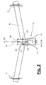
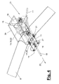
- Figure 3 to 7 and 8 to 10 different ways with the Mounting directly on the axle body or on the abutment (21). at multi-axle vehicle trailers (1) can one or more Rollers brakes (13) in a corresponding arrangement to be available.
- the Schlinger brake (13) also at another suitable place of the Accommodate the vehicle trailer (1).
- the roll brake (13) has a power supply (22), which are integrated in the rolling brake (13) can, e.g. in the form of a battery.
- a power supply 22
- the power supply (22) is preferably electric, but can also be of any other nature be.
- the roll brake (13) consists of a measuring device (14), a controller (19) and an actuator (15) with an actuating element (17) which is connected to the balance beam (16) or another suitable connection element in Engage intervention and the brake cables (11) can operate.
- the measuring device (14) is used for detection and recording from rolling motions.
- the occurring when rolling Vibrations are due to a specific frequency band characterized.
- lateral acceleration of the vehicle trailer (1) in both directions and over a certain period of time added to a distinction from others in the normal driving occurring lateral acceleration to meet.
- the yaw rate, i. the Angular velocity around the vertical axis measured.
- Rolling movements are based on the aforementioned Detected frequency band.
- you can Longitudinal accelerations are detected.
- a recording of inclinations of the vehicle trailer about the longitudinal axis and possibly also around the transverse axis are possible.
- the measuring device (14) can be of any suitable Be constructive training and can also be to any be arranged appropriate place.
- the frame (20) can on the axis (8) in be attached in any way. In Figure 3 to 7 it is directly attached to the axle body (8). It can be at one Original equipment e.g. be welded.
- Retrofitting to existing vehicle trailers (1) (1) can be a Clamping by means of clamps or the like. Provided be. When retrofitting can be a suitable additional abutment (21) attached to the frame (20) be.
- the measuring device is (14) also on the assembly and in the frame (20) arranged.
- Figure 2 shows a variant in which a Measuring unit (14) at a rear corner of the Vehicle trailer (1) attached and via appropriate Lines with the controller (19) and the power supply (22) of the roll brake (13) is connected. At this Vehicle corners occur the largest lateral accelerations, so that the best measuring possibilities exist here. Of the Construction and assembly costs are slightly higher than in the preferred integral design.
- Such ESP sensor arrangements can be multiple times and in different places of the vehicle trailer (1) be arranged.
- the controller (19) is connected to the measuring device (14) connected and can be integrated into the ESP sensor assembly or arranged separately with connection to several sensors be. It contains a comparison and Control device used by the measuring device (14) delivered measured data evaluated and given Setpoints are compared. In addition, an internal Comparison with previously recorded and saved Measurements take place to the reactions of Vehicle trailer (1) on the function of the rolling brake (13) and to determine the operation of the wheel brakes (9). About the controller (19) is thus a regulation of Rolling brake (13) possible.
- the actuator (15) has a motor (18) and a thereto Directly connected power and road transmitting Actuator (17) which is connected to the balance beam (16) directly or indirectly via the Brake transmission device (10) is engaged.
- the Motor (18) is connected to the controller (19) and is controlled by this. He owns a fast Responsiveness and high acceleration, so he upon activation of the skid brake (13) the wheel brakes (9) in a short reaction time of preferably below 1 sec.
- the possibly with a transmission (34) Equipped motor (18) is connected to the actuator (17) in a direct operative connection, wherein he the actuator (17) in the operating or pulling direction (23) of Brake transmission device (10) controlled moves.
- the controller (19) moves the Motor (18) again for brake release to the starting position back.
- the engine movements determine the Brake application.
- the actuating forces and actuating movements of the controller (19) acted upon motor (18) are on the Control element (17) directly on the balance beam (16) for Transfer operation of the brake cables (11).
- the operation of the balance beam (16) and the brake cables (11) through the Actuator (15) remains for the duration of Lingering brake operation maintained.
- the Actuator (15) can thus via the motor (18) at any time control the braking effect and in response to the Regulate rolling behavior.
- the motor (18) is preferably electrical Geared motor with a gearbox (34), e.g. one Planetary gear and a preferably linearly movable Output member (40), e.g. an extendable spindle, a Rack or the like formed. He is e.g. when so-called electric cylinder with a low-friction Ball screw designed.
- the output member (40), in particular in the form of a threaded spindle, especially one Trapezoidal spindle, may alternatively be self-locking.
- the rod-like adjusting element (17) may be in one piece or be multi-part and consists e.g. from the output drive (40) and an actuator (25), e.g. one Push rod, which in the embodiment of Figure 3 to 7 connected by a fitting (29) and directly are coupled. This results in a length-stable Control element (7) whose length is fixed in braking mode.
- a similar fitting (29), the motor (18) on be stored at the rear end of the frame (20).
- the Fittings (29) may have limited angular movements at the Allow connection point.
- the adjusting element (17) is in the variant of Figure 3 to 7 rod-shaped and pressure-resistant.
- the actuator (15) in Direction of travel seen at the rear of the axle (8) arranged, wherein the connecting element (16) or the balance beam, located at the front.
- the actuator (17) via the push rod (25) in one-sided stop connection with the balance beam (16). It starts when the skid brake (13) is actuated and exerts pressure forces on the balance beam (16).
- the Control element (17) can in the inactive starting position on the balance beam (16) or at a short distance be distanced.
- the adjusting element (17) can be made adjustable in length be and this any suitable constructive Have design, e.g. as a telescopic pole with Locking possibility in different extension positions. This allows retrofitting without installation Adjustment of the existing braking device (4).
- the Length adjustment relates to a basic setting of Actuator length at commissioning, at Maintenance or emergency release done and is substantially constant during operation remains.
- the adjusting element (17) is at least partially, in particular in the area of the push rod (25), as a tube trained and has at least at its the balance beam (16) facing front a pipe opening (26).
- This pipe opening (26) is the pipe or the push rod (25) on the rear pin (27) of the brake linkage (10) plugged and guided longitudinally movable.
- the Push rod (25) lies with its front end on Driver (28) in a one-way driver connection, in particular a thrust connection to.
- the push rod (25) penetrates the at the bottom of the axle body (8) arranged abutment (21) and can in the local Passage be guided.
- the brake linkage (10) in Pulling direction (23) are moved, which by the Casserole device is intercepted.
- the motor-driven Extending movement of the actuating element (17) is in Dependence on the reaction of trailer movements the braking forces regulated. As long as the rolling effects and In particular, the lateral accelerations, exist, the Maintained braking effect and possibly enlarged. If Slack effects and lateral accelerations will subside the motor (18) driven in the opposite direction and retracts the control element (17) again.
- the return springs in the wheel brakes (9) pull the brake cables (11) and the balance beam (16) together with the brake linkage (10) and back to the starting position.
- the function of the rolling brake (13) can from the Vehicle driver by a braking reaction and a Operation of the service brake (5) are superimposed.
- By the longitudinally movable guide of the tube (25) on the pin (27) can be the balance beam (16) from the actuator (17) in the pulling direction (23). This relative movement can also in normal driving and braking operation and not active anti-roll brake (13) take place.
- the roll brake (13) can be a tracking device (30) (not shown in FIGS. 3 to 7) to be used in the Driving with not actuated service brake (5) the Control element (17) in stop position on To hold connecting element (16) or on the driver (28).
- the actuator (15) can this Compensation follow and the stop contact of the Control element (17) on the driver (28) or on Maintaining connection element (16).
- This Tracking may be controlled, depending on what different way is possible, e.g. through a contact or force measurement, a position measurement of Connecting element (16) or otherwise.
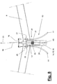
- FIG. 7 to 9 show different variants of Rolling brake (13).
- the modifications affect on the one hand the possibility of mounting on the abutment (21).
- the axle body (8) can multiply in number, shape and arrangement Vary way.
- the abutment (21), however, is usually on the same location on the axle and arranged varies hardly in its shape.
- a suitable Holder (35) are used, preferably as Clamping device is formed.
- FIG. 10 shows this an embodiment in detail.
- the holder (35) consists made of two angled jaws (36,37), which are in Inside a cutout (39) to carry out the Have brake cables (11) and the adjusting element (17).
- the a jaw (37) may also have a U-shaped Support rail for receiving the frame or housing (20) exhibit.
- FIGS. 8 and 9 illustrate a further modification, which relates to the design of the actuating element (17).
- a spring unit (31) By the inserted spring unit (31) an axial relative movement between the output member (40) and push rod (25) during operation possible.
- the aforementioned Basic adjustment of the actuator length can thereby Operational changes.
- In the thrust direction is the Relativweg by the moving on block spring limited.
- the relative movement is through a bow-shaped or cage-like guide (33) limited.
- the Guide (33) consists e.g.
- the output member (40) presses, e.g. the spindle shown in Figure 9, on the spring unit (31) and then back on the push rod (25).
- the equipped with a compression spring spring unit (31) even with the engine off, a spring force on the Push rod (25) and over the balance beam (16) on the Apply brake cables (11), so that the brake cables (11) at Occurrence of subsidence in the brake or cable area in Rolling brake operation automatically and without Motor Nach ein can be tightened. Furthermore Can wear in a relaxed rest position compensating adjustment of the brake cables (11) take place.
- the Spring unit (31) also the push rod (27) in constant contact with the connecting element (16) or the driver (28).
- the rollback brake (13) This immediately responds to an engine operation and actuates the wheel brakes without delay.
- On the spring unit (31) can also have one or more Switch (32), in particular mechanical limit switches, inductive displacement sensors, radiometric Hall sensors or Like., Be appropriate. This can be a force limit the actuator (15) can be realized. This is also for the control loop overrun brake (5) and skid brake (13) beneficial. If e.g. with activated overrun brake (5) the rolling brake (13) is triggered and the Motor movement is controlled only via the current consumption, The wheel brakes (9) could be over tightened. Of the Motor (18) and the self-locking spindle (40) would then stay in this suit position.
- the Spring unit (31) acts in such a case compensating, over the said limit switch the Motor (18) is switched off when the push rod (25) stops when the wheel brakes (9) and the Spindle (40) continues to the specified load and Moving limit extends.
- a relaxation of the spring unit (31) detected by one or more of the switches (32) become.
- This can be interpreted in various ways and be used.
- In the extended clamping position or Ringer braking position when the engine is off (18) can at a significant spring relaxation of the engine (18) if necessary, with continued lurching again be turned on.
- the relaxation path of the guide elements or the bracket of the guide (33) limited in terms of switching.
- the Switch position can be selected so that the Spring unit (31) is still under tension and a Restweg for the aforementioned retightening of the brake cables (11) can perform.
- FIG. 9 shows an embodiment of the rolling brake (13), particularly suitable for mounting on the abutment (21) suitable.
- the housing (20) is narrow and in this case if necessary, tapering to the front, so that it on Abutment (21) between the brake cables (21) mounted can be.
- the holder (35) is in Figure 9 only indicated. It can in the illustrated in Figure 10 Be formed manner or in another way.
- the latter is aligned with the spring unit (31) with the Connecting rod (25) connected, which along the extends front narrow housing area and through the Abutment (21) protrudes.
- Figure 9 is also the multipart Training possibility of the actuating element (17) indicated.
- the push rod (25) of two consist of interconnected halves, e.g. above a thread are connected longitudinally adjustable.
- the roll brake (13) can hereby by a controlled clutch, a deactivated Actuator (15) or otherwise in the normal Operating cases switched off and only in the event of a fall be switched on. Furthermore, it is possible that Actuator (17) instead of the connecting element (16) directly to connect to the brake transmission device (10). Also in this case is a direct connection between the brake cables (11) and the actuator (15) given the a permanent control or regulation of Schlinger braking effect allows. Variables are also the constructive embodiments of the rolling brake (13), in particular the design of the engine (18) and the Control element (17).
- the motor (40) may e.g. one be hydraulic or pneumatic drive. Similarly its output member (4) can be designed differently and generate a different output movement.
- the different Components of the roll brake (13) can be separated from each other and at different points of the Vehicle trailer (1) are arranged.
Landscapes
- Engineering & Computer Science (AREA)
- Transportation (AREA)
- Mechanical Engineering (AREA)
- Regulating Braking Force (AREA)
- Braking Arrangements (AREA)
- Metal Rolling (AREA)
- Braking Systems And Boosters (AREA)
Priority Applications (2)
| Application Number | Priority Date | Filing Date | Title |
|---|---|---|---|
| EP08004060.3A EP1942037B2 (fr) | 2004-05-19 | 2005-05-12 | Frein à roulis pour une remorque de véhicule |
| SI200530304T SI1598249T2 (sl) | 2004-05-19 | 2005-05-12 | Nagibna zavora za priklopnik vozila |
Applications Claiming Priority (2)
| Application Number | Priority Date | Filing Date | Title |
|---|---|---|---|
| DE202004008160U DE202004008160U1 (de) | 2004-05-19 | 2004-05-19 | Schlingerbremse für Fahrzeuganhänger |
| DE202004008160U | 2004-05-19 |
Related Child Applications (2)
| Application Number | Title | Priority Date | Filing Date |
|---|---|---|---|
| EP08004060.3A Division EP1942037B2 (fr) | 2004-05-19 | 2005-05-12 | Frein à roulis pour une remorque de véhicule |
| EP08004060.3A Division-Into EP1942037B2 (fr) | 2004-05-19 | 2005-05-12 | Frein à roulis pour une remorque de véhicule |
Publications (3)
| Publication Number | Publication Date |
|---|---|
| EP1598249A1 true EP1598249A1 (fr) | 2005-11-23 |
| EP1598249B1 EP1598249B1 (fr) | 2008-04-09 |
| EP1598249B2 EP1598249B2 (fr) | 2014-01-29 |
Family
ID=34936457
Family Applications (2)
| Application Number | Title | Priority Date | Filing Date |
|---|---|---|---|
| EP08004060.3A Ceased EP1942037B2 (fr) | 2004-05-19 | 2005-05-12 | Frein à roulis pour une remorque de véhicule |
| EP05010373.8A Expired - Lifetime EP1598249B2 (fr) | 2004-05-19 | 2005-05-12 | Frein anti-devers pour remorques |
Family Applications Before (1)
| Application Number | Title | Priority Date | Filing Date |
|---|---|---|---|
| EP08004060.3A Ceased EP1942037B2 (fr) | 2004-05-19 | 2005-05-12 | Frein à roulis pour une remorque de véhicule |
Country Status (4)
| Country | Link |
|---|---|
| EP (2) | EP1942037B2 (fr) |
| AT (1) | ATE391646T1 (fr) |
| DE (3) | DE202004008160U1 (fr) |
| SI (1) | SI1598249T2 (fr) |
Cited By (14)
| Publication number | Priority date | Publication date | Assignee | Title |
|---|---|---|---|---|
| EP1795422A1 (fr) * | 2005-12-08 | 2007-06-13 | Knott GmbH | Frein d'inertie pour remorques avec capteur de déplacement dans le barre d'attelage |
| EP2022692A2 (fr) * | 2007-08-06 | 2009-02-11 | BPW Fahrzeugtechnik GmbH & Co. KG | Dispositif et procédé de reconnaissance de la course à vide de remorques dotées de freins de véhicule à inertie |
| DE202009005185U1 (de) | 2009-08-26 | 2011-01-20 | Al-Ko Kober Ag | Hilfsantrieb |
| DE202010008600U1 (de) | 2010-09-21 | 2011-12-27 | Al-Ko Kober Ag | Hilfsfahrantrieb |
| DE202015104525U1 (de) | 2015-08-26 | 2016-12-01 | Alois Kober Gmbh | Schlingerbremseinrichtung |
| DE202016100947U1 (de) | 2016-02-23 | 2017-05-24 | Alois Kober Gmbh | Stabilisierungseinrichtung |
| CN107685780A (zh) * | 2017-07-26 | 2018-02-13 | 南京航空航天大学 | 一种客车电磁防侧翻装置及方法 |
| DE202017101795U1 (de) * | 2017-03-28 | 2018-07-11 | AL-KO Technology Austria GmbH | Erfassungseinrichtung und Stabilisierungseinrichtung |
| DE202018102469U1 (de) * | 2018-05-03 | 2019-05-16 | Knott Gmbh | Anhängerstabilisierungseinrichtung für einen Anhänger sowie Anhänger |
| DE102018110011A1 (de) * | 2018-04-26 | 2019-10-31 | Humbaur Gmbh | Schleuderschutzsystem für einen Fahrzeuganhänger |
| CN110395289A (zh) * | 2019-07-19 | 2019-11-01 | 中国水利水电第十二工程局有限公司 | 一种斜井运输车抱轨自紧装置 |
| EP3656619A1 (fr) * | 2018-11-19 | 2020-05-27 | Alois Kober GmbH | Dispositif électrique d'entraînement et de freinage |
| EP3166825B1 (fr) | 2014-07-08 | 2021-01-13 | Lippert Components Inc. | Dispositif de commande de détection d'oscillation et de stabilité de remorque du type adaptatif |
| DE202021102632U1 (de) | 2020-05-19 | 2021-06-10 | Knott Gmbh | Anhängerstabilisierungseinrichtung zur Stabilisierung eines Anhängers |
Families Citing this family (13)
| Publication number | Priority date | Publication date | Assignee | Title |
|---|---|---|---|---|
| DE102007051304A1 (de) * | 2007-08-06 | 2009-02-12 | Bpw Bergische Achsen Kg | Zusatzbremssystem und Verfahren zur Betätigung von Fahrzeugbremsen |
| EP2022654B1 (fr) * | 2007-08-06 | 2010-11-24 | BPW Fahrzeugtechnik GmbH & Co. KG | Système de frein supplémentaire et procédé d'actionnement de freins de véhicule |
| DE102014213425A1 (de) * | 2014-07-10 | 2016-01-14 | Volkswagen Aktiengesellschaft | Handbremsseil, Hinterradachse, Montageverfahren und Kraftfahrzeug |
| EP3176042B1 (fr) | 2015-12-03 | 2021-01-20 | AL-KO Technology Austria GmbH | Technique de stabilisation pour remorques de véhicule |
| DE202015106595U1 (de) | 2015-12-03 | 2017-03-07 | AL-KO Technology Austria GmbH | Stabilisierungstechnik für Fahrzeuganhänger |
| DE202016101279U1 (de) | 2016-03-08 | 2017-06-09 | Alois Kober Gmbh | Antriebseinheit |
| EP3379222B1 (fr) | 2017-03-22 | 2020-12-30 | Methode Electronics Malta Ltd. | Ensemble de capteur à base magnétoélastique |
| US11135882B2 (en) | 2018-02-27 | 2021-10-05 | Methode Electronics, Inc. | Towing systems and methods using magnetic field sensing |
| US10670479B2 (en) | 2018-02-27 | 2020-06-02 | Methode Electronics, Inc. | Towing systems and methods using magnetic field sensing |
| US11084342B2 (en) | 2018-02-27 | 2021-08-10 | Methode Electronics, Inc. | Towing systems and methods using magnetic field sensing |
| US11221262B2 (en) | 2018-02-27 | 2022-01-11 | Methode Electronics, Inc. | Towing systems and methods using magnetic field sensing |
| US11491832B2 (en) | 2018-02-27 | 2022-11-08 | Methode Electronics, Inc. | Towing systems and methods using magnetic field sensing |
| DE202019101716U1 (de) | 2019-03-26 | 2020-06-29 | Alois Kober Gmbh | Steuertechnik für Anhänger-Schlingerbremseinrichtung |
Citations (3)
| Publication number | Priority date | Publication date | Assignee | Title |
|---|---|---|---|---|
| DE29607092U1 (de) * | 1996-04-19 | 1996-10-17 | Lubs, Wolfgang, 50996 Köln | Elektronisches Antischlinger-System |
| DE10215617A1 (de) * | 2002-04-09 | 2003-11-20 | Continental Teves Ag & Co Ohg | Einrichtung zum Stabilisieren eines Anhängers |
| DE20312130U1 (de) * | 2003-09-25 | 2004-02-12 | Lubs, Wolfgang | Elektronisches Anhänger Stablisierungssystem |
Family Cites Families (7)
| Publication number | Priority date | Publication date | Assignee | Title |
|---|---|---|---|---|
| DE2914940A1 (de) * | 1979-04-12 | 1980-10-30 | Bernhard Krunke | Vorrichtung zum verhindern des schleuderns von strassenfahrzeugen gezogenen anhaengern |
| DE2952093A1 (de) † | 1979-12-22 | 1981-07-02 | Sachs Systemtechnik Gmbh, 8720 Schweinfurt | Bremsbetaetigung fuer anhaenger-auflaufbremsen |
| DE3937210C2 (de) † | 1989-11-08 | 1996-09-05 | Wiedenmann Gmbh | Kehrgerät |
| DE9016918U1 (de) † | 1990-12-14 | 1991-06-06 | Lubs, Wolfgang, 5000 Köln | Schlingerstopvorrichtung |
| DE19913342C2 (de) † | 1997-09-26 | 2002-09-19 | Johannes Gubernath | Schlingerdämpfer |
| DE29721843U1 (de) † | 1997-12-11 | 1999-04-22 | AL-KO Kober AG, 89359 Kötz | Seilzugeinstellung für eine Bremseinrichtung |
| GB2362693A (en) † | 2000-05-23 | 2001-11-28 | Allan Arthur Askey | Braking device for a towed vehicle e.g.a caravan |
-
2004
- 2004-05-19 DE DE202004008160U patent/DE202004008160U1/de not_active Expired - Lifetime
-
2005
- 2005-05-12 EP EP08004060.3A patent/EP1942037B2/fr not_active Ceased
- 2005-05-12 DE DE502005003611T patent/DE502005003611D1/de not_active Expired - Lifetime
- 2005-05-12 EP EP05010373.8A patent/EP1598249B2/fr not_active Expired - Lifetime
- 2005-05-12 AT AT05010373T patent/ATE391646T1/de not_active IP Right Cessation
- 2005-05-12 SI SI200530304T patent/SI1598249T2/sl unknown
- 2005-05-12 DE DE502005010193T patent/DE502005010193D1/de not_active Expired - Lifetime
Patent Citations (4)
| Publication number | Priority date | Publication date | Assignee | Title |
|---|---|---|---|---|
| DE29607092U1 (de) * | 1996-04-19 | 1996-10-17 | Lubs, Wolfgang, 50996 Köln | Elektronisches Antischlinger-System |
| DE10215617A1 (de) * | 2002-04-09 | 2003-11-20 | Continental Teves Ag & Co Ohg | Einrichtung zum Stabilisieren eines Anhängers |
| DE20312130U1 (de) * | 2003-09-25 | 2004-02-12 | Lubs, Wolfgang | Elektronisches Anhänger Stablisierungssystem |
| DE202004006324U1 (de) * | 2003-09-25 | 2004-07-29 | Lubs, Wolfgang, Dipl.-Ing. | Bremseinrichtung für einen Fahrzeuganhänger |
Cited By (23)
| Publication number | Priority date | Publication date | Assignee | Title |
|---|---|---|---|---|
| EP1795422A1 (fr) * | 2005-12-08 | 2007-06-13 | Knott GmbH | Frein d'inertie pour remorques avec capteur de déplacement dans le barre d'attelage |
| EP2022692A2 (fr) * | 2007-08-06 | 2009-02-11 | BPW Fahrzeugtechnik GmbH & Co. KG | Dispositif et procédé de reconnaissance de la course à vide de remorques dotées de freins de véhicule à inertie |
| DE202009005185U1 (de) | 2009-08-26 | 2011-01-20 | Al-Ko Kober Ag | Hilfsantrieb |
| EP2289776A2 (fr) | 2009-08-26 | 2011-03-02 | AL-KO Kober AG | Dispositif d'entraînement secondaire pour une remorque |
| DE202010008600U1 (de) | 2010-09-21 | 2011-12-27 | Al-Ko Kober Ag | Hilfsfahrantrieb |
| EP3166825B1 (fr) | 2014-07-08 | 2021-01-13 | Lippert Components Inc. | Dispositif de commande de détection d'oscillation et de stabilité de remorque du type adaptatif |
| DE202015104525U1 (de) | 2015-08-26 | 2016-12-01 | Alois Kober Gmbh | Schlingerbremseinrichtung |
| DE102016115873A1 (de) | 2015-08-26 | 2017-03-02 | Alois Kober Gmbh | Schlingerbremseinrichtung |
| DE202016100947U1 (de) | 2016-02-23 | 2017-05-24 | Alois Kober Gmbh | Stabilisierungseinrichtung |
| DE102017103777A1 (de) | 2016-02-23 | 2017-08-24 | Alois Kober Gmbh | Stabilisierungseinrichtung und Stabilisierungsverfahren |
| DE202017101795U1 (de) * | 2017-03-28 | 2018-07-11 | AL-KO Technology Austria GmbH | Erfassungseinrichtung und Stabilisierungseinrichtung |
| WO2018177975A1 (fr) | 2017-03-28 | 2018-10-04 | AL-KO Technology Austria GmbH | Dispositif de détection, procédé de détection et dispositif de stabilisation |
| CN107685780A (zh) * | 2017-07-26 | 2018-02-13 | 南京航空航天大学 | 一种客车电磁防侧翻装置及方法 |
| CN107685780B (zh) * | 2017-07-26 | 2024-03-29 | 南京航空航天大学 | 一种客车电磁防侧翻装置及方法 |
| DE102018110011A1 (de) * | 2018-04-26 | 2019-10-31 | Humbaur Gmbh | Schleuderschutzsystem für einen Fahrzeuganhänger |
| DE202018102469U1 (de) * | 2018-05-03 | 2019-05-16 | Knott Gmbh | Anhängerstabilisierungseinrichtung für einen Anhänger sowie Anhänger |
| EP3564051A1 (fr) * | 2018-05-03 | 2019-11-06 | Reich GmbH Regel- und Sicherheitstechnik | Dispositif de stabilisation de remorque ainsi que remorque |
| EP3656619A1 (fr) * | 2018-11-19 | 2020-05-27 | Alois Kober GmbH | Dispositif électrique d'entraînement et de freinage |
| CN110395289A (zh) * | 2019-07-19 | 2019-11-01 | 中国水利水电第十二工程局有限公司 | 一种斜井运输车抱轨自紧装置 |
| DE202021102632U1 (de) | 2020-05-19 | 2021-06-10 | Knott Gmbh | Anhängerstabilisierungseinrichtung zur Stabilisierung eines Anhängers |
| EP3912871A1 (fr) | 2020-05-19 | 2021-11-24 | Reich GmbH Regel- und Sicherheitstechnik | Dispositif de stabilisation de remorque et procédé de stabilisation d'une remorque |
| DE102020113509A1 (de) | 2020-05-19 | 2021-11-25 | Knott Gmbh | Anhängerstabilisierungseinrichtung und Verfahren zur Stabilisierung eines Anhängers |
| DE102020113509B4 (de) | 2020-05-19 | 2024-02-01 | Knott Gmbh | Anhängerstabilisierungseinrichtung, Verfahren zur Stabilisierung eines Anhängers, Computerprogramm und Anhänger |
Also Published As
| Publication number | Publication date |
|---|---|
| EP1942037A2 (fr) | 2008-07-09 |
| DE202004008160U1 (de) | 2005-09-29 |
| DE502005010193D1 (de) | 2010-10-14 |
| EP1598249B2 (fr) | 2014-01-29 |
| SI1598249T1 (sl) | 2008-10-31 |
| EP1942037A3 (fr) | 2008-07-23 |
| EP1942037B2 (fr) | 2017-06-21 |
| EP1598249B1 (fr) | 2008-04-09 |
| DE502005003611D1 (de) | 2008-05-21 |
| SI1598249T2 (sl) | 2014-04-30 |
| EP1942037B1 (fr) | 2010-09-01 |
| ATE391646T1 (de) | 2008-04-15 |
Similar Documents
| Publication | Publication Date | Title |
|---|---|---|
| EP1598249B2 (fr) | Frein anti-devers pour remorques | |
| DE60103553T2 (de) | Elektromotorische feststellbremsanlage | |
| EP0832000B1 (fr) | Accouplement de remorque | |
| EP2110271B1 (fr) | Attelage | |
| DE102017107064B3 (de) | Fahrzeuganhänger mit Energierückgewinnungseinrichtung | |
| EP1380445B1 (fr) | Dispositif de traction de remorque | |
| EP2022654B1 (fr) | Système de frein supplémentaire et procédé d'actionnement de freins de véhicule | |
| DE102011003791A1 (de) | System zum automatischen Einstellen eines Spaltraumes zwischen einem Motorwagen und einem daran angekuppelten Anhänger | |
| EP2070736A2 (fr) | Dispositif d'attelage de remorque doté d'un dispositif de stabilisation destiné à éviter et/ou amortir les mouvements de louvoiement entre un véhicule tracteur et une remorque attachée | |
| EP3299192B1 (fr) | Dispositif de frein additionnel pour une remorque de véhicule pourvue d'un système de freinage par inertie | |
| AT507594B1 (de) | Zwangslenkung | |
| WO2009086897A2 (fr) | Auxiliaire de montage et procédé de montage | |
| WO2014023426A1 (fr) | Dispositif générateur de force, en particulier pour un frein de stationnement | |
| DE3033582C2 (fr) | ||
| DE102006033569B4 (de) | Betätigungsvorrichtung für eine Bremseinrichtung | |
| EP2093110B1 (fr) | Frein de stationnement | |
| DE202004006324U1 (de) | Bremseinrichtung für einen Fahrzeuganhänger | |
| DE202022102008U1 (de) | Arretiereinrichtung | |
| DE19913342A1 (de) | Schlingerdämpfer | |
| DE102005062563B4 (de) | Elektronisches Stabilitätssystem für Fahrräder | |
| DE102004006801A1 (de) | Feststellbremseinrichtung | |
| DE202005019223U1 (de) | Auflaufbremsanlage für Kraftfahrzeuganhänger mit Wegmesseinrichtung für Zugstange | |
| DE1680381C3 (de) | Bremseinheit für klotzgebremste Schienenfahrzeuge | |
| DE2629360C2 (fr) | ||
| DE102005019827B4 (de) | Winkelstellungssensor für ein Gespann aus einem Antriebsfahrzeug und einem mit diesem gekuppelten Folgefahrzeug sowie Antriebsfahrzeug mit Winkelstellungssensor |
Legal Events
| Date | Code | Title | Description |
|---|---|---|---|
| PUAI | Public reference made under article 153(3) epc to a published international application that has entered the european phase |
Free format text: ORIGINAL CODE: 0009012 |
|
| AK | Designated contracting states |
Kind code of ref document: A1 Designated state(s): AT BE BG CH CY CZ DE DK EE ES FI FR GB GR HU IE IS IT LI LT LU MC NL PL PT RO SE SI SK TR |
|
| AX | Request for extension of the european patent |
Extension state: AL BA HR LV MK YU |
|
| 17P | Request for examination filed |
Effective date: 20060317 |
|
| AKX | Designation fees paid |
Designated state(s): AT BE BG CH CY CZ DE DK EE ES FI FR GB GR HU IE IS IT LI LT LU MC NL PL PT RO SE SI SK TR |
|
| GRAP | Despatch of communication of intention to grant a patent |
Free format text: ORIGINAL CODE: EPIDOSNIGR1 |
|
| GRAS | Grant fee paid |
Free format text: ORIGINAL CODE: EPIDOSNIGR3 |
|
| GRAA | (expected) grant |
Free format text: ORIGINAL CODE: 0009210 |
|
| AK | Designated contracting states |
Kind code of ref document: B1 Designated state(s): AT BE BG CH CY CZ DE DK EE ES FI FR GB GR HU IE IS IT LI LT LU MC NL PL PT RO SE SI SK TR |
|
| REG | Reference to a national code |
Ref country code: GB Ref legal event code: FG4D Free format text: NOT ENGLISH |
|
| REG | Reference to a national code |
Ref country code: CH Ref legal event code: EP |
|
| REG | Reference to a national code |
Ref country code: IE Ref legal event code: FG4D Free format text: LANGUAGE OF EP DOCUMENT: GERMAN |
|
| REF | Corresponds to: |
Ref document number: 502005003611 Country of ref document: DE Date of ref document: 20080521 Kind code of ref document: P |
|
| REG | Reference to a national code |
Ref country code: SE Ref legal event code: TRGR |
|
| PG25 | Lapsed in a contracting state [announced via postgrant information from national office to epo] |
Ref country code: PT Free format text: LAPSE BECAUSE OF FAILURE TO SUBMIT A TRANSLATION OF THE DESCRIPTION OR TO PAY THE FEE WITHIN THE PRESCRIBED TIME-LIMIT Effective date: 20080910 Ref country code: FI Free format text: LAPSE BECAUSE OF FAILURE TO SUBMIT A TRANSLATION OF THE DESCRIPTION OR TO PAY THE FEE WITHIN THE PRESCRIBED TIME-LIMIT Effective date: 20080409 Ref country code: ES Free format text: LAPSE BECAUSE OF FAILURE TO SUBMIT A TRANSLATION OF THE DESCRIPTION OR TO PAY THE FEE WITHIN THE PRESCRIBED TIME-LIMIT Effective date: 20080720 Ref country code: BG Free format text: LAPSE BECAUSE OF FAILURE TO SUBMIT A TRANSLATION OF THE DESCRIPTION OR TO PAY THE FEE WITHIN THE PRESCRIBED TIME-LIMIT Effective date: 20080709 |
|
| PG25 | Lapsed in a contracting state [announced via postgrant information from national office to epo] |
Ref country code: PL Free format text: LAPSE BECAUSE OF FAILURE TO SUBMIT A TRANSLATION OF THE DESCRIPTION OR TO PAY THE FEE WITHIN THE PRESCRIBED TIME-LIMIT Effective date: 20080409 |
|
| BERE | Be: lapsed |
Owner name: AL-KO KOBER A.G. Effective date: 20080531 |
|
| REG | Reference to a national code |
Ref country code: IE Ref legal event code: FD4D |
|
| PG25 | Lapsed in a contracting state [announced via postgrant information from national office to epo] |
Ref country code: MC Free format text: LAPSE BECAUSE OF NON-PAYMENT OF DUE FEES Effective date: 20080531 Ref country code: IS Free format text: LAPSE BECAUSE OF FAILURE TO SUBMIT A TRANSLATION OF THE DESCRIPTION OR TO PAY THE FEE WITHIN THE PRESCRIBED TIME-LIMIT Effective date: 20080809 |
|
| ET | Fr: translation filed | ||
| PLBI | Opposition filed |
Free format text: ORIGINAL CODE: 0009260 |
|
| PG25 | Lapsed in a contracting state [announced via postgrant information from national office to epo] |
Ref country code: CZ Free format text: LAPSE BECAUSE OF FAILURE TO SUBMIT A TRANSLATION OF THE DESCRIPTION OR TO PAY THE FEE WITHIN THE PRESCRIBED TIME-LIMIT Effective date: 20080409 Ref country code: LT Free format text: LAPSE BECAUSE OF FAILURE TO SUBMIT A TRANSLATION OF THE DESCRIPTION OR TO PAY THE FEE WITHIN THE PRESCRIBED TIME-LIMIT Effective date: 20080409 Ref country code: EE Free format text: LAPSE BECAUSE OF FAILURE TO SUBMIT A TRANSLATION OF THE DESCRIPTION OR TO PAY THE FEE WITHIN THE PRESCRIBED TIME-LIMIT Effective date: 20080409 Ref country code: DK Free format text: LAPSE BECAUSE OF FAILURE TO SUBMIT A TRANSLATION OF THE DESCRIPTION OR TO PAY THE FEE WITHIN THE PRESCRIBED TIME-LIMIT Effective date: 20080409 Ref country code: IE Free format text: LAPSE BECAUSE OF FAILURE TO SUBMIT A TRANSLATION OF THE DESCRIPTION OR TO PAY THE FEE WITHIN THE PRESCRIBED TIME-LIMIT Effective date: 20080409 |
|
| PLAX | Notice of opposition and request to file observation + time limit sent |
Free format text: ORIGINAL CODE: EPIDOSNOBS2 |
|
| 26 | Opposition filed |
Opponent name: BPW BERGISCHE ACHSEN KG Effective date: 20090106 |
|
| PG25 | Lapsed in a contracting state [announced via postgrant information from national office to epo] |
Ref country code: SK Free format text: LAPSE BECAUSE OF FAILURE TO SUBMIT A TRANSLATION OF THE DESCRIPTION OR TO PAY THE FEE WITHIN THE PRESCRIBED TIME-LIMIT Effective date: 20080409 Ref country code: RO Free format text: LAPSE BECAUSE OF FAILURE TO SUBMIT A TRANSLATION OF THE DESCRIPTION OR TO PAY THE FEE WITHIN THE PRESCRIBED TIME-LIMIT Effective date: 20080409 |
|
| PG25 | Lapsed in a contracting state [announced via postgrant information from national office to epo] |
Ref country code: BE Free format text: LAPSE BECAUSE OF NON-PAYMENT OF DUE FEES Effective date: 20080531 |
|
| NLR1 | Nl: opposition has been filed with the epo |
Opponent name: BPW BERGISCHE ACHSEN KG |
|
| PLAF | Information modified related to communication of a notice of opposition and request to file observations + time limit |
Free format text: ORIGINAL CODE: EPIDOSCOBS2 |
|
| PLBB | Reply of patent proprietor to notice(s) of opposition received |
Free format text: ORIGINAL CODE: EPIDOSNOBS3 |
|
| PG25 | Lapsed in a contracting state [announced via postgrant information from national office to epo] |
Ref country code: AT Free format text: LAPSE BECAUSE OF NON-PAYMENT OF DUE FEES Effective date: 20080512 Ref country code: IT Free format text: LAPSE BECAUSE OF FAILURE TO SUBMIT A TRANSLATION OF THE DESCRIPTION OR TO PAY THE FEE WITHIN THE PRESCRIBED TIME-LIMIT Effective date: 20080409 |
|
| PG25 | Lapsed in a contracting state [announced via postgrant information from national office to epo] |
Ref country code: CY Free format text: LAPSE BECAUSE OF FAILURE TO SUBMIT A TRANSLATION OF THE DESCRIPTION OR TO PAY THE FEE WITHIN THE PRESCRIBED TIME-LIMIT Effective date: 20080409 |
|
| REG | Reference to a national code |
Ref country code: CH Ref legal event code: PL |
|
| PG25 | Lapsed in a contracting state [announced via postgrant information from national office to epo] |
Ref country code: CH Free format text: LAPSE BECAUSE OF NON-PAYMENT OF DUE FEES Effective date: 20090531 Ref country code: LI Free format text: LAPSE BECAUSE OF NON-PAYMENT OF DUE FEES Effective date: 20090531 |
|
| APBM | Appeal reference recorded |
Free format text: ORIGINAL CODE: EPIDOSNREFNO |
|
| APBP | Date of receipt of notice of appeal recorded |
Free format text: ORIGINAL CODE: EPIDOSNNOA2O |
|
| APAH | Appeal reference modified |
Free format text: ORIGINAL CODE: EPIDOSCREFNO |
|
| APBM | Appeal reference recorded |
Free format text: ORIGINAL CODE: EPIDOSNREFNO |
|
| APBP | Date of receipt of notice of appeal recorded |
Free format text: ORIGINAL CODE: EPIDOSNNOA2O |
|
| APBQ | Date of receipt of statement of grounds of appeal recorded |
Free format text: ORIGINAL CODE: EPIDOSNNOA3O |
|
| PG25 | Lapsed in a contracting state [announced via postgrant information from national office to epo] |
Ref country code: LU Free format text: LAPSE BECAUSE OF NON-PAYMENT OF DUE FEES Effective date: 20080512 Ref country code: HU Free format text: LAPSE BECAUSE OF FAILURE TO SUBMIT A TRANSLATION OF THE DESCRIPTION OR TO PAY THE FEE WITHIN THE PRESCRIBED TIME-LIMIT Effective date: 20081010 |
|
| APBQ | Date of receipt of statement of grounds of appeal recorded |
Free format text: ORIGINAL CODE: EPIDOSNNOA3O |
|
| PG25 | Lapsed in a contracting state [announced via postgrant information from national office to epo] |
Ref country code: TR Free format text: LAPSE BECAUSE OF FAILURE TO SUBMIT A TRANSLATION OF THE DESCRIPTION OR TO PAY THE FEE WITHIN THE PRESCRIBED TIME-LIMIT Effective date: 20080409 |
|
| PG25 | Lapsed in a contracting state [announced via postgrant information from national office to epo] |
Ref country code: GR Free format text: LAPSE BECAUSE OF FAILURE TO SUBMIT A TRANSLATION OF THE DESCRIPTION OR TO PAY THE FEE WITHIN THE PRESCRIBED TIME-LIMIT Effective date: 20080710 |
|
| APBU | Appeal procedure closed |
Free format text: ORIGINAL CODE: EPIDOSNNOA9O |
|
| PUAH | Patent maintained in amended form |
Free format text: ORIGINAL CODE: 0009272 |
|
| STAA | Information on the status of an ep patent application or granted ep patent |
Free format text: STATUS: PATENT MAINTAINED AS AMENDED |
|
| 27A | Patent maintained in amended form |
Effective date: 20140129 |
|
| AK | Designated contracting states |
Kind code of ref document: B2 Designated state(s): AT BE BG CH CY CZ DE DK EE ES FI FR GB GR HU IE IS IT LI LT LU MC NL PL PT RO SE SI SK TR |
|
| REG | Reference to a national code |
Ref country code: DE Ref legal event code: R102 Ref document number: 502005003611 Country of ref document: DE |
|
| REG | Reference to a national code |
Ref country code: DE Ref legal event code: R102 Ref document number: 502005003611 Country of ref document: DE Effective date: 20140129 |
|
| REG | Reference to a national code |
Ref country code: NL Ref legal event code: T3 |
|
| REG | Reference to a national code |
Ref country code: SE Ref legal event code: RPEO |
|
| REG | Reference to a national code |
Ref country code: FR Ref legal event code: PLFP Year of fee payment: 11 |
|
| REG | Reference to a national code |
Ref country code: DE Ref legal event code: R082 Ref document number: 502005003611 Country of ref document: DE Representative=s name: ERNICKE & ERNICKE, DE Ref country code: DE Ref legal event code: R081 Ref document number: 502005003611 Country of ref document: DE Owner name: AL-KO TECHNOLOGY AUSTRIA GMBH, AT Free format text: FORMER OWNER: AL-KO KOBER AG, 89359 KOETZ, DE Ref country code: DE Ref legal event code: R082 Ref document number: 502005003611 Country of ref document: DE Representative=s name: ERNICKE PATENT- UND RECHTSANWAELTE, DE |
|
| REG | Reference to a national code |
Ref country code: SI Ref legal event code: SP73 Owner name: AL-KO TECHNOLOGY AUSTRIA GMBH; AT Effective date: 20151217 |
|
| REG | Reference to a national code |
Ref country code: FR Ref legal event code: CJ Effective date: 20160203 |
|
| REG | Reference to a national code |
Ref country code: FR Ref legal event code: TP Owner name: AL-KO TECHNOLOGY AUSTRIA GMBH, AT Effective date: 20160302 |
|
| REG | Reference to a national code |
Ref country code: NL Ref legal event code: PD Owner name: AL-KO TECHNOLOGY AUSTRIA GMBH; AT Free format text: DETAILS ASSIGNMENT: VERANDERING VAN EIGENAAR(S), OVERDRACHT; FORMER OWNER NAME: AL-KO KOBER SE Effective date: 20151210 Ref country code: NL Ref legal event code: HC Owner name: AL-KO KOBER SE; DE Free format text: DETAILS ASSIGNMENT: VERANDERING VAN EIGENAAR(S), VERANDERING VAN NAAM VAN DE EIGENAAR(S); FORMER OWNER NAME: AL-KO KOBER AG Effective date: 20151210 |
|
| REG | Reference to a national code |
Ref country code: FR Ref legal event code: PLFP Year of fee payment: 12 |
|
| REG | Reference to a national code |
Ref country code: FR Ref legal event code: PLFP Year of fee payment: 13 |
|
| REG | Reference to a national code |
Ref country code: GB Ref legal event code: 732E Free format text: REGISTERED BETWEEN 20170629 AND 20170705 |
|
| REG | Reference to a national code |
Ref country code: FR Ref legal event code: PLFP Year of fee payment: 14 |
|
| PGFP | Annual fee paid to national office [announced via postgrant information from national office to epo] |
Ref country code: NL Payment date: 20190523 Year of fee payment: 15 |
|
| PGFP | Annual fee paid to national office [announced via postgrant information from national office to epo] |
Ref country code: SI Payment date: 20190410 Year of fee payment: 15 Ref country code: FR Payment date: 20190416 Year of fee payment: 15 Ref country code: SE Payment date: 20190416 Year of fee payment: 15 |
|
| REG | Reference to a national code |
Ref country code: NL Ref legal event code: MM Effective date: 20200601 |
|
| PG25 | Lapsed in a contracting state [announced via postgrant information from national office to epo] |
Ref country code: SE Free format text: LAPSE BECAUSE OF NON-PAYMENT OF DUE FEES Effective date: 20200513 |
|
| PG25 | Lapsed in a contracting state [announced via postgrant information from national office to epo] |
Ref country code: NL Free format text: LAPSE BECAUSE OF NON-PAYMENT OF DUE FEES Effective date: 20200601 |
|
| PG25 | Lapsed in a contracting state [announced via postgrant information from national office to epo] |
Ref country code: FR Free format text: LAPSE BECAUSE OF NON-PAYMENT OF DUE FEES Effective date: 20200531 |
|
| REG | Reference to a national code |
Ref country code: SI Ref legal event code: KO00 Effective date: 20210317 |
|
| PG25 | Lapsed in a contracting state [announced via postgrant information from national office to epo] |
Ref country code: SI Free format text: LAPSE BECAUSE OF NON-PAYMENT OF DUE FEES Effective date: 20200513 |
|
| PGFP | Annual fee paid to national office [announced via postgrant information from national office to epo] |
Ref country code: DE Payment date: 20230519 Year of fee payment: 19 |
|
| PGFP | Annual fee paid to national office [announced via postgrant information from national office to epo] |
Ref country code: GB Payment date: 20230522 Year of fee payment: 19 |
|
| REG | Reference to a national code |
Ref country code: DE Ref legal event code: R119 Ref document number: 502005003611 Country of ref document: DE |
|
| GBPC | Gb: european patent ceased through non-payment of renewal fee |
Effective date: 20240512 |
|
| PG25 | Lapsed in a contracting state [announced via postgrant information from national office to epo] |
Ref country code: DE Free format text: LAPSE BECAUSE OF NON-PAYMENT OF DUE FEES Effective date: 20241203 |
|
| PG25 | Lapsed in a contracting state [announced via postgrant information from national office to epo] |
Ref country code: GB Free format text: LAPSE BECAUSE OF NON-PAYMENT OF DUE FEES Effective date: 20240512 |