EP3912871A1 - Dispositif de stabilisation de remorque et procédé de stabilisation d'une remorque - Google Patents
Dispositif de stabilisation de remorque et procédé de stabilisation d'une remorque Download PDFInfo
- Publication number
- EP3912871A1 EP3912871A1 EP21173907.3A EP21173907A EP3912871A1 EP 3912871 A1 EP3912871 A1 EP 3912871A1 EP 21173907 A EP21173907 A EP 21173907A EP 3912871 A1 EP3912871 A1 EP 3912871A1
- Authority
- EP
- European Patent Office
- Prior art keywords
- trailer
- wheel
- brake
- stabilization device
- detection device
- Prior art date
- Legal status (The legal status is an assumption and is not a legal conclusion. Google has not performed a legal analysis and makes no representation as to the accuracy of the status listed.)
- Withdrawn
Links
Images



Classifications
-
- B—PERFORMING OPERATIONS; TRANSPORTING
- B60—VEHICLES IN GENERAL
- B60D—VEHICLE CONNECTIONS
- B60D1/00—Traction couplings; Hitches; Draw-gear; Towing devices
- B60D1/58—Auxiliary devices
- B60D1/62—Auxiliary devices involving supply lines, electric circuits or the like
-
- B—PERFORMING OPERATIONS; TRANSPORTING
- B60—VEHICLES IN GENERAL
- B60D—VEHICLE CONNECTIONS
- B60D1/00—Traction couplings; Hitches; Draw-gear; Towing devices
- B60D1/24—Traction couplings; Hitches; Draw-gear; Towing devices characterised by arrangements for particular functions
- B60D1/30—Traction couplings; Hitches; Draw-gear; Towing devices characterised by arrangements for particular functions for sway control ; Sway alarm means
-
- B—PERFORMING OPERATIONS; TRANSPORTING
- B60—VEHICLES IN GENERAL
- B60T—VEHICLE BRAKE CONTROL SYSTEMS OR PARTS THEREOF; BRAKE CONTROL SYSTEMS OR PARTS THEREOF, IN GENERAL; ARRANGEMENT OF BRAKING ELEMENTS ON VEHICLES IN GENERAL; PORTABLE DEVICES FOR PREVENTING UNWANTED MOVEMENT OF VEHICLES; VEHICLE MODIFICATIONS TO FACILITATE COOLING OF BRAKES
- B60T7/00—Brake-action initiating means
- B60T7/12—Brake-action initiating means for automatic initiation; for initiation not subject to will of driver or passenger
- B60T7/20—Brake-action initiating means for automatic initiation; for initiation not subject to will of driver or passenger specially for trailers, e.g. in case of uncoupling of or overrunning by trailer
-
- B—PERFORMING OPERATIONS; TRANSPORTING
- B60—VEHICLES IN GENERAL
- B60T—VEHICLE BRAKE CONTROL SYSTEMS OR PARTS THEREOF; BRAKE CONTROL SYSTEMS OR PARTS THEREOF, IN GENERAL; ARRANGEMENT OF BRAKING ELEMENTS ON VEHICLES IN GENERAL; PORTABLE DEVICES FOR PREVENTING UNWANTED MOVEMENT OF VEHICLES; VEHICLE MODIFICATIONS TO FACILITATE COOLING OF BRAKES
- B60T8/00—Arrangements for adjusting wheel-braking force to meet varying vehicular or ground-surface conditions, e.g. limiting or varying distribution of braking force
- B60T8/17—Using electrical or electronic regulation means to control braking
- B60T8/1701—Braking or traction control means specially adapted for particular types of vehicles
- B60T8/1708—Braking or traction control means specially adapted for particular types of vehicles for lorries or tractor-trailer combinations
-
- F—MECHANICAL ENGINEERING; LIGHTING; HEATING; WEAPONS; BLASTING
- F16—ENGINEERING ELEMENTS AND UNITS; GENERAL MEASURES FOR PRODUCING AND MAINTAINING EFFECTIVE FUNCTIONING OF MACHINES OR INSTALLATIONS; THERMAL INSULATION IN GENERAL
- F16D—COUPLINGS FOR TRANSMITTING ROTATION; CLUTCHES; BRAKES
- F16D66/00—Arrangements for monitoring working conditions, e.g. wear, temperature
-
- B—PERFORMING OPERATIONS; TRANSPORTING
- B60—VEHICLES IN GENERAL
- B60T—VEHICLE BRAKE CONTROL SYSTEMS OR PARTS THEREOF; BRAKE CONTROL SYSTEMS OR PARTS THEREOF, IN GENERAL; ARRANGEMENT OF BRAKING ELEMENTS ON VEHICLES IN GENERAL; PORTABLE DEVICES FOR PREVENTING UNWANTED MOVEMENT OF VEHICLES; VEHICLE MODIFICATIONS TO FACILITATE COOLING OF BRAKES
- B60T2230/00—Monitoring, detecting special vehicle behaviour; Counteracting thereof
- B60T2230/06—Tractor-trailer swaying
-
- F—MECHANICAL ENGINEERING; LIGHTING; HEATING; WEAPONS; BLASTING
- F16—ENGINEERING ELEMENTS AND UNITS; GENERAL MEASURES FOR PRODUCING AND MAINTAINING EFFECTIVE FUNCTIONING OF MACHINES OR INSTALLATIONS; THERMAL INSULATION IN GENERAL
- F16D—COUPLINGS FOR TRANSMITTING ROTATION; CLUTCHES; BRAKES
- F16D66/00—Arrangements for monitoring working conditions, e.g. wear, temperature
- F16D2066/003—Position, angle or speed
Definitions
- the invention relates to a trailer stabilization device for a trailer, in particular for a caravan, a caravan, a boat trailer, a sales vehicle, a transport trailer or a car transport trailer.
- the invention also relates to a method for stabilizing and regulating the driving state of a trailer, in particular a caravan, a caravan, a boat trailer, a sales car, a transport trailer or a car transport trailer.
- the trailer stabilization device comprises at least one actuator, by means of which a journey of the trailer can be stabilized when the actuator is operated.
- the actuator comprises at least one actuator, by means of which a journey of the trailer can be stabilized when the actuator is operated.
- This is to be understood in particular as the fact that undesired movements of the trailer can be counteracted, in particular actively counteracted, by means of the actuator by operating the actuator.
- a desired state, in particular a desired driving state, of the trailer can be brought about.
- unwanted or excessive body movements of the trailer relative to a road along which the trailer is traveling avoided or such undesirable body movements are counteracted.
- trailer stabilization devices of the type considered here are from DE 20 2016 104 675 U1 , which discloses an additional braking device for an overrun braked vehicle trailer or the DE 20 2015 106 595 U1 which shows a stabilization technique for vehicle trailers.
- DE 10 2012 016 234 A1 a trailer for a vehicle is known.
- US 2018/0086227 A1 discloses an apparatus with a towed vehicle for Use in combination with a towing vehicle.
- a regenerative braking system for a towed vehicle can be found as known.
- the GB 2 409 712 A discloses an anti-roll braking system for a trailer.
- From the EP 1 598 249 A1 a roll brake for vehicle trailers is known.
- the object of the present invention is to further develop a trailer stabilization device and a method for stabilizing and regulating the driving state of a trailer in such a way that they reliably and unambiguously recognize and identify the driving state of the trailer and also ensure particularly safe operation of the trailer.
- a first aspect of the invention relates to a trailer stabilization device for a trailer, in particular for a caravan, a caravan, a boat trailer, a sales van, a transport trailer or a car transport trailer.
- the trailer stabilization device according to the invention comprises at least one speed detection device for determining the speed of at least one trailer wheel, the speed detection device having at least two permanent magnets as a pulse generator of a pulse detection device and the permanent magnets on a rotating element of a trailer brake and / or a rim of the trailer wheel and / or on at least one Carriers are arranged, the carrier being arranged between the rotating element of the trailer brake and the rim of the trailer wheel.
- the trailer stabilization device comprises at least one electronic control device connected to the pulse detection device for Control of at least one brake actuator to regulate the speed of the trailer wheel by means of a braking device acting on the at least one trailer wheel, the control device controlling the brake actuator as a function of the detected speeds of the at least one trailer wheel.
- the trailer stabilization device advantageously ensures that the driving state of the trailer is reliably and unambiguously recognized and identified. In addition, a particularly safe operation of the trailer is guaranteed, since the current driving state of the trailer can be continuously checked by the current speed detection of the at least one trailer wheel by means of the speed detection device.
- the control device controls the brake actuator in such a way that the trailer wheels are prevented from locking during the control and regulation of the speed of the at least one trailer wheel.
- the evaluation of the wheel speed to prevent locking in connection with the stabilizing brake intervention makes it possible for the stabilization intervention to be carried out specifically to the traction limit of the trailer wheels via the control device and the brake actuator.
- further factors such as, for example, the coefficient of adhesion between tire and road or the current wheel contact force, do not have to be taken into account.
- the trailer stabilization device according to the invention therefore enables a safe and also functionally simple stabilization of the trailer while driving.
- the rotating element of the trailer brake can be, for example, a brake hub, a brake drum, a brake disc or a brake disc carrier.
- the pulse detection device comprises at least one magnetic field sensor past which the permanent magnets are guided.
- the magnetic field sensor is connected to the control device in the usual way, which then evaluates and processes the received speed data accordingly.
- the pulse detection device is also designed as an electrical generator.
- the pulse detection device forms an electrical generator for generating electrical energy.
- the pulse detection device can for example comprise at least one coil which is arranged in such a way that, while leaving a gap forming a gap close to an orbit of the permanent magnets, they are guided past the coil and an electrical voltage is thus induced due to the movement of the permanent magnets.
- the individual voltage pulses of this generator can be used as a pole wheel for the trailer stabilization device.
- the voltage ripple is used as an angular momentum to record the speed of the trailer wheel.
- the dual function of the pulse detection device as a component of a speed detection device and for determining a corresponding speed of trailer wheels, as well as the design as an electrical generator for generating energy, has a number of advantages. So far, there has been the problem that towing vehicles, in particular passenger cars, with the exhaust gas classification "Euro 6" or higher often have a permanent power supply via a 13-pin trailer connector to switch off the trailer in order to relieve the load on the alternator or the engine and to be able to comply with the relevant emissions standards. As soon as the power supply to the trailer is switched off, all systems in the trailer are de-energized and cannot work. This also applies in particular to the known trailer stabilization systems.
- the pulse detection device is designed as an electrical generator.
- the energy supply of the trailer stabilization device can namely be operated via the energy generated by the pulse detection device.
- the trailer stabilization device comprises at least one energy store for storing and releasing the energy generated by means of the permanent magnets in connection with the at least one coil.
- Energy storage can be, for example, an accumulator or a capacitor.
- Other types of energy storage devices are also conceivable.
- the energy store can then be designed to supply energy to the trailer stabilization device and / or the control device and / or the brake actuator and / or other electrical consumers of the trailer.
- the energy store also comprises at least one connection element which can be connected to an energy source of a towing vehicle designed to provide energy for moving the trailer, so that the energy store can be supplied and charged with energy provided by the energy source via the connection element .
- trailer stabilization device according to the invention can also be operated safely in the event that the power supply from the towing vehicle to the trailer is switched off.
- This also applies to all other electrical systems that are electrically connected to the energy store of the trailer stabilization device or the pulse detection device acting as an electrical generator and are supplied with energy accordingly.
- the permanent magnets are arranged alternately with different polarity and form the aforementioned pole wheel.
- the pole wheel designed in this way is - as already explained - used as a speed sensor and scanned accordingly.
- the permanent magnets are arranged on a rotating element of a trailer brake and / or a rim of the trailer wheel and / or on at least one carrier.
- the permanent magnets can for example be arranged on the outside of a brake hub or a brake drum of the brake hub.
- the permanent magnets can also be arranged on a rim.
- the arrangement of the permanent magnets on a separately designed carrier which is arranged between the brake hub and the rim of the trailer wheel is also conceivable.
- the permanent magnets can be arranged on a disc brake, in particular on a carrier for the brake discs.
- a large number of magnets can be provided, which are arranged at equidistant intervals from one another and, in their arrangement, form the said magnet wheel.
- the permanent magnets are arranged on the brake drum, they can be attached to the brake drum on the outer circumference, that is to say at a radial distance from the axis of rotation.
- the permanent magnets are arranged on the separately designed carrier, they also form a pole wheel with an annular arrangement of the magnets.
- the pole wheel formed according to the invention can also be mounted on one or all axles of the trailer and is connected directly or indirectly via the energy store to the electromechanical trailer stabilization device.
- the coil of the pulse detection device is mounted directly or via a coil holder on a chassis of the trailer, an axle construction of the trailer, a rocker arm of a trailer wheel or a brake carrier plate.
- the coil can be installed in a stationary or also displaceable manner.
- the Pulse detection device comprises at least two coils, these being arranged out of phase with one another. With such a configuration there is advantageously the possibility of also determining the direction of rotation of the trailer wheel.
- the trailer stabilization device comprises at least one acceleration sensor and / or at least one yaw rate sensor, the acceleration sensor and / or the yaw rate sensor being connected to the control device.
- the acceleration and / or inclination data determined by means of the acceleration sensor and / or yaw rate sensor can also be used to monitor reaching a locking limit of the trailer wheels.
- this can comprise at least one display device for displaying and displaying the state of charge of the energy store.
- a 2-color LED or a text display can be arranged on a trailer drawbar of the trailer, on which the user can see the state of charge of the energy storage device and / or a result of a possible self-test of the energy storage device and / or the general operational readiness when the trailer is coupled to the towing vehicle of the energy store and / or the trailer stabilization device is informed.
- the trailer stabilization device comprises at least one radio system for the wireless transmission of status data, in particular charge status data of the energy store, to a display device.
- the corresponding status data and / or warnings in the event of a low sensor level of the energy store can be transmitted to a corresponding display device via Bluetooth.
- the display device can be a display arranged in the towing vehicle or the trailer, a display of a mobile phone, a laptop, a tablet and comparable devices. It is therefore advantageously possible for the driver of the utility vehicle at any time to be informed about the charge state of the energy store, for example, and in particular about possible critical states of the charge state of the energy store.
- the carrier of the permanent magnets is designed in such a way that it can be slipped over and attached to an outer surface of the rotating element of the trailer brake, for example the brake hub.
- the carrier can have at least one opening for air cooling of the rotating element of the trailer brake connected to the carrier, for example the brake hub.
- Such a carrier ensures according to the invention that trailers can also be retrofitted with the trailer stabilization device according to the invention. There is no need for functional or technical interventions in existing systems. In addition, it is ensured that the functionality of the rotating element of the trailer brake, for example the brake hub, is not impaired.
- the openings in the carrier ensure sufficient air cooling of the rotating element, such as the brake hub, for example.
- the design of the carrier can have independent inventive features that present a separate inventive aspect.
- a second aspect of the present invention relates to a method for stabilizing and regulating the driving state of a trailer, in particular a caravan, a caravan, a boat trailer, a sales car, a transport trailer or a car transport trailer.
- the method comprises at least the following steps: Determination of the speed of at least one trailer wheel of the trailer by means of a speed detection device, the speed detection device having at least two permanent magnets as a pulse generator of a pulse detection device and the permanent magnets on a rotating element of a trailer brake and / or a rim of the trailer wheel and / or are arranged on at least one carrier, the carrier being arranged between the rotating element of the trailer brake and the rim of the trailer wheel.
- the speed of the at least one trailer wheel is controlled and regulated by means of an electronic control device connected to the pulse detection device for controlling at least one brake actuator, the brake actuator being designed to regulate the speed of the trailer wheel by means of a braking device acting on the at least one trailer wheel.
- the control device controls the brake actuator as a function of the detected rotational speeds of the at least one trailer wheel.
- the driving state of a trailer can be reliably and unambiguously recognized and identified.
- the method ensures a special safeguard during operation of the trailer, since this is based exclusively on the current speed measurements of the trailer wheels or the trailer wheel.
- Other factors that can influence the swaying behavior of the trailer such as the difference between the empty weight and the permissible total weight of the trailer, coefficients of friction between the trailer wheel and the roadway do not necessarily have to be recorded, as this is reflected in the measured speeds via the control of the Speed of the trailer wheel, i.e. controlled braking of the trailer wheel, counteracts an unstable driving condition of the trailer, such as, for example, during rolling movements.
- control device can control the brake actuator in such a way that the trailer wheels are prevented from locking during the control and regulation of the speed of the at least one trailer wheel.
- the stabilization intervention can be operated in a targeted manner up to a frictional connection limit of the trailer wheels.
- additional data and assumptions such as the tire-road adhesion coefficient or current wheel contact force values can be dispensed with. If the tendency to lock is detected, the method according to the invention readjusts the speed of the wheels.
- the measured speed can be used to map the current speed of the trailer.
- the measured speed can also be multiplied by the measured tendency of the trailer to roll and compared with a predetermined limit value. If this product exceeds the limit value, a stabilization intervention is also initiated via the control device.
- the braking force can in turn be increased up to the detection of a tendency to lock on one or more trailer wheels.
- a so-called trailer delay value can also be used as a limit value for the end of the stabilization intervention.
- the strength of the stabilization intervention can also be used more powerful, but in this case the trailer's brake lights would have to be activated.
- the method according to the invention advantageously also enables evaluation and control strategies that avoid or help to regulate extreme cases of driving conditions of the trailer.
- the inner wheel of a lurching trailer lifts off the ground and thus locks with the slightest brake actuation.
- the control device can be designed in such a way that such blockages are filtered out, so that only the outer, more heavily loaded trailer wheel determines the control in the control.
- the control device is designed in such a way that the current rolling movements of the trailer are also taken into account in the stabilization control.
- the braking force can be increased from a zero crossing, which is defined by the exact position of the longitudinal axis of the trailer, to the apex of the rolling movement and reduced during the swing back. This can prevent the lurching trailer from experiencing an additional movement impulse when it swings back to the zero position.
- design options of the method according to the invention in particular the design of the control device or the individual functions of the control device, can have independent inventive features which, if necessary, present an inventive aspect even without detecting the speed of the trailer wheels.
- the permanent magnets interact with at least one magnetic field sensor past which the permanent magnets are guided and / or with at least one coil for inducing an electrical voltage.
- the interaction of the permanent magnets with the at least one coil leads to the design of the pulse detection device as an additional electrical generator.
- the energy generated with this electrical generator can then be used in at least one Energy storage can be stored.
- the energy stored in this way can be used to supply energy to the trailer stabilization device and / or the control device and / or the brake actuator and / or electrical consumers of the trailer.
- a third aspect of the invention relates to a computer program comprising commands which cause the trailer stabilization device according to the first aspect of the invention to carry out the method steps according to the second aspect of the invention.
- a fourth aspect of the invention relates to a trailer, in particular a caravan, caravan, boat trailer, sales van, transport trailer or car transport trailer, with at least one trailer stabilization device according to the first aspect of the invention.
- Fig. 1 shows a schematic perspective view of a trailer with a trailer stabilization device 24 according to a first embodiment.
- the Trailer comprises a chassis 10 with a frame or a frame 12 which, among other things, has two longitudinal members 14, 16 running in the longitudinal direction of the chassis 10.
- An axle 18 is also provided, which at each end interacts with a trailer wheel 20, 22.
- a brake actuator 28 is also arranged on the chassis 10, which is designed to actuate corresponding brake devices 58 on the one rotating element of a trailer brake, here the brake hubs 36 of the trailer wheels 20, 22.
- the brake devices 58 are each connected to the brake actuator 28 via a cable 34.
- the wheels 20, 22 provided at the end of the axle 18 each have a corresponding rim 38 in a manner known per se, each of which is equipped with a tire when it is ready for operation.
- the trailer stabilization device 24 also has a speed detection device 26 for determining the speed of the respective trailer wheel 20, 22.
- the speed detection device 26 is also equipped with an electronic control device 30 for controlling the brake actuator 28 and thus for controlling and regulating the speed of the trailer wheels 20, 22 by means of the braking device 58 acting on the trailer wheels 20, 22.
- the control device 30 controls the brake actuator 28 as a function of the detected rotational speeds of the trailer wheels 20, 22.
- An energy store 32 is also arranged on the axle 18, in particular permanently connected to the axle 18. In the Fig. 1 and the following figures, individual electrical lines that connect the various elements of the trailer stabilization device 24 to one another are not explicitly shown.
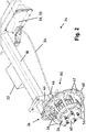
- the Fig. 2 and 3 each show schematic detailed views of the trailer stabilization device 24 according to FIG Fig. 1 .
- the rotational speed detection device 26 has a plurality of permanent magnets 42 arranged in a circle around the brake hub 36.
- the permanent magnets 42 serve as pulse generators of a pulse detection device 44 and are arranged on a carrier 40 in the exemplary embodiment shown.
- the carrier 40 forms with a removable Outer ring 60 has corresponding openings 56 for receiving and fastening the permanent magnets 42.
- the carrier 40 is designed overall like a pot or bowl, in such a way that it can be slipped over an outer surface of the brake hub 36 and fastened thereto.
- the side wall of the carrier 40 has struts 54 which surround openings 56.
- the openings 56 serve for air cooling of the brake hub 36 arranged below.
- the brake hub 36 is arranged at the end of the axle 18 with a rocker arm 50 interposed. This is exemplified in the Fig. 2 and 3 shown using the trailer wheel 22 on the left in the direction of travel. It can also be seen that the braking device 58 is connected to the brake actuator 28 via the cable 34. The brake actuator 28 is regulated or controlled by means of the control device 30.
- the carrier 40 is arranged between the respective brake hub 36 and the respective rim 38 (not shown) of the trailer wheels 20, 22.
- the pulse detection device 44 comprises two coils 46 which are arranged in such a way that the permanent magnets 42 are guided past the coils 46 while leaving a gap forming a gap close to an orbit. Due to the movement of the permanent magnets 42, an electrical voltage is induced here.
- the coils 46 can be designed as so-called air-core coils or consist of what are known as transformer core sheets. Other coil types are also conceivable.
- two coils 46 are arranged, which are arranged out of phase with one another. This makes it possible to also detect the direction of rotation of the trailer wheels 20, 22.
- the permanent magnets 42 are arranged in the usual manner with different polarity.
- the energy generated by means of the permanent magnets 42 in connection with the coils 46 is stored in the energy store 32.
- the coils 46 are connected in the usual way to the energy store 32 via electrical lines (not shown).
- the energy store 32 is used to supply energy to the trailer stabilization device 24 as a whole or to individual elements of the Trailer stabilization device 24, such as, for example, the control device 30 or the brake actuator 28.
- the energy store 32 is used to supply energy to electrical consumers of the trailer.
- the energy store 32 comprises at least one connection element (not shown) which can be connected to an energy source of a towing vehicle designed to provide energy for moving the trailer. In this case, the energy store 32 can be supplied and charged with energy provided by the energy source via the connection element.
- the supply voltage from the towing vehicle is applied in this way, it is preferably used for charging the energy store 32.
- a protective circuit (not shown) prevents the return flow to the towing vehicle through the electrical energy obtained by the pulse detection device 44 or the permanent magnet 42 in connection with the coils 46. Due to the energy generated by means of the pulse detection device 44, the trailer stabilization device 24 can, however, be actuated independently of the power supply of the towing vehicle.
- the energy store 32 can also be releasably attached to the axle 18, for example by means of U-bolts or via a bracket attached to the axle 18. In this case, the energy store 32 can also be changed without any problems.
- the bobbins 46 can be installed directly or via a bobbin holder 48 (cf. Fig. 5 and 6th ) be mounted on the chassis 10, the axle structure of the trailer, the rocker arm 50 or a brake carrier plate.
- FIG. 13 shows a schematic perspective view of the carrier 40 of the trailer stabilization device 24 according to FIG Figs. 1 to 3 .
- the overall pot-like or bowl-like configuration of the carrier 40 can be seen.
- the inner circumference of the carrier 40 is dimensioned in such a way that it can be slipped over a brake hub 36 of the trailer wheel 20, 22.
- the struts 54 for forming the side walls of the carrier 40 are formed between the openings 56.
- the permanent magnets 42 are arranged in alternating alignment uniformly and in a circular manner on the area of the outer edge of the carrier 40 closed off by the outer ring 60.
- the openings 56 are formed to accommodate the permanent magnets 42.
- Fig. 5 shows a schematic detailed view of a trailer stabilization device 24 according to a second embodiment.
- the permanent magnets 42 are arranged on the outer circumference of the brake hub 36.
- the pulse detection device 44 has only one coil 46, which is fastened to the rocker arm 50 of the trailer wheel via a coil holder 48.
- the brake device 58 is in turn connected to a brake actuator 28, not shown in this figure, via the cable 34.
- the arrangement of a shock absorber 52 between the longitudinal member 14 and the rocker arm 50 can be seen.
- Fig. 6 shows a schematic detailed view of a trailer stabilization direction according to a third embodiment.
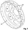
- Fig. 7 which is a schematic perspective view of a carrier 40 of the trailer stabilization device 24 according to FIG Fig. 6 shows, it is clear that the permanent magnets 42 are again arranged on a separately formed carrier 40.
- the carrier 40 is in turn fastened to the brake hub 36 between the brake hub 36 and the rim, not shown, of the trailer wheel.
- the permanent magnets 42 are here arranged equidistantly on an outer ring of the carrier 40, which is also designed like a bowl or pot.
- the permanent magnets 42 are alternately provided with different polarities.
- the carrier 40 To cool the brake hub 36, the carrier 40 according to the embodiment described here also has openings 56 for air cooling.
- the pulse detection device 44 comprises a coil 46 which is fastened to a coil holder 48.
- the bobbin holder 48 is in turn arranged on the rocker arm 50.
- the braking device 58 is also actuated by means of the cable 34 in this exemplary embodiment.
Landscapes
- Engineering & Computer Science (AREA)
- Mechanical Engineering (AREA)
- Transportation (AREA)
- General Engineering & Computer Science (AREA)
- Regulating Braking Force (AREA)
Applications Claiming Priority (1)
| Application Number | Priority Date | Filing Date | Title |
|---|---|---|---|
| DE102020113509.2A DE102020113509B4 (de) | 2020-05-19 | 2020-05-19 | Anhängerstabilisierungseinrichtung, Verfahren zur Stabilisierung eines Anhängers, Computerprogramm und Anhänger |
Publications (1)
| Publication Number | Publication Date |
|---|---|
| EP3912871A1 true EP3912871A1 (fr) | 2021-11-24 |
Family
ID=75936768
Family Applications (1)
| Application Number | Title | Priority Date | Filing Date |
|---|---|---|---|
| EP21173907.3A Withdrawn EP3912871A1 (fr) | 2020-05-19 | 2021-05-14 | Dispositif de stabilisation de remorque et procédé de stabilisation d'une remorque |
Country Status (2)
| Country | Link |
|---|---|
| EP (1) | EP3912871A1 (fr) |
| DE (2) | DE102020113509B4 (fr) |
Cited By (1)
| Publication number | Priority date | Publication date | Assignee | Title |
|---|---|---|---|---|
| DE102023102840A1 (de) | 2023-02-06 | 2024-08-08 | Knott Gmbh | Anhänger für ein zugfahrzeug sowie verfahren zum betreiben eines solchen anhängers |
Families Citing this family (3)
| Publication number | Priority date | Publication date | Assignee | Title |
|---|---|---|---|---|
| EP4245619B1 (fr) * | 2022-03-16 | 2024-04-24 | Knott GmbH | Système de stabilisation pour une remorque de véhicule et procédé de stabilisation |
| DE202022103880U1 (de) | 2022-07-11 | 2022-08-01 | Knott Gmbh | Anhängerstabilisierungssystem für einen Fahrzeuganhänger |
| DE202022103881U1 (de) | 2022-07-11 | 2022-08-01 | Knott Gmbh | Anhängerstabilisierungssystem für einen Fahrzeuganhänger mit Drehzahlsensor |
Citations (15)
| Publication number | Priority date | Publication date | Assignee | Title |
|---|---|---|---|---|
| EP1107007A2 (fr) * | 1999-11-30 | 2001-06-13 | Volkswagen Aktiengesellschaft | Dispositif de détermination de la rotation d'une roue d'un véhicule, dispositif de freinage pour roues d'un véhicule, et procédé pour contrôler la force de freinage |
| GB2409712A (en) | 2003-12-30 | 2005-07-06 | John Hanlon | Caravan / trailer anti-snaking braking system |
| EP1598249A1 (fr) | 2004-05-19 | 2005-11-23 | Al-Ko Kober Ag | Frein anti-devers pour remorques |
| US20060091723A1 (en) * | 2004-10-29 | 2006-05-04 | Gunite Corporation | Exciter ring for a brake rotor |
| DE102006007871A1 (de) * | 2005-03-03 | 2006-09-21 | Continental Teves Ag & Co. Ohg | Sensor und Verfahren zur Erfaasung von Ortsverschiebungen und Drehbewegungen |
| US20080169144A1 (en) | 2007-01-03 | 2008-07-17 | Degrave Ken | Hybrid trailer system |
| DE102007036202B4 (de) * | 2007-11-02 | 2010-03-11 | Knorr-Bremse Systeme für Nutzfahrzeuge GmbH | Prüf- und Simulationsschaltung für Magnetfeldsensoren |
| DE102012016234A1 (de) | 2012-08-07 | 2014-02-13 | e-drives UG (haftungsbeschränkt) | Anhänger für ein Fahrzeug und Verfahren zur Steuerung und Betrieb |
| DE202016104675U1 (de) | 2016-08-25 | 2016-11-03 | Bpw Fahrzeugtechnik Gmbh & Co. Kg | Zusatzbremseinrichtung für einen auflaufgebremsten Fahrzeuganhänger sowie Fahrzeuganhänger |
| DE202015106595U1 (de) | 2015-12-03 | 2017-03-07 | AL-KO Technology Austria GmbH | Stabilisierungstechnik für Fahrzeuganhänger |
| DE102017115445A1 (de) * | 2016-07-26 | 2018-02-01 | Knott Gmbh | Anhängerstabilisierungssystem zur Reduzierung von Schlingerbewegungen von Fahrzeuganhängern |
| US20180086227A1 (en) | 2015-05-01 | 2018-03-29 | Hyliion Inc. | Trailer-based energy capture and management |
| DE202018102469U1 (de) * | 2018-05-03 | 2019-05-16 | Knott Gmbh | Anhängerstabilisierungseinrichtung für einen Anhänger sowie Anhänger |
| DE102018204442A1 (de) * | 2018-03-22 | 2019-09-26 | Zf Friedrichshafen Ag | Verfahren und Steuergerät zum Bestimmen einer Orientierung eines Anhängers |
| US20200122692A1 (en) * | 2018-10-23 | 2020-04-23 | Dexter Axle Company | Wheel sensors within vehicular brake assemblies |
Family Cites Families (1)
| Publication number | Priority date | Publication date | Assignee | Title |
|---|---|---|---|---|
| DE102008040712A1 (de) | 2008-07-25 | 2010-01-28 | Robert Bosch Gmbh | Verfahren zur Ermittlung einer Fahrzeugzustandsgröße in Fahrzeuggespannen |
-
2020
- 2020-05-19 DE DE102020113509.2A patent/DE102020113509B4/de active Active
-
2021
- 2021-05-14 DE DE202021102632.4U patent/DE202021102632U1/de active Active
- 2021-05-14 EP EP21173907.3A patent/EP3912871A1/fr not_active Withdrawn
Patent Citations (15)
| Publication number | Priority date | Publication date | Assignee | Title |
|---|---|---|---|---|
| EP1107007A2 (fr) * | 1999-11-30 | 2001-06-13 | Volkswagen Aktiengesellschaft | Dispositif de détermination de la rotation d'une roue d'un véhicule, dispositif de freinage pour roues d'un véhicule, et procédé pour contrôler la force de freinage |
| GB2409712A (en) | 2003-12-30 | 2005-07-06 | John Hanlon | Caravan / trailer anti-snaking braking system |
| EP1598249A1 (fr) | 2004-05-19 | 2005-11-23 | Al-Ko Kober Ag | Frein anti-devers pour remorques |
| US20060091723A1 (en) * | 2004-10-29 | 2006-05-04 | Gunite Corporation | Exciter ring for a brake rotor |
| DE102006007871A1 (de) * | 2005-03-03 | 2006-09-21 | Continental Teves Ag & Co. Ohg | Sensor und Verfahren zur Erfaasung von Ortsverschiebungen und Drehbewegungen |
| US20080169144A1 (en) | 2007-01-03 | 2008-07-17 | Degrave Ken | Hybrid trailer system |
| DE102007036202B4 (de) * | 2007-11-02 | 2010-03-11 | Knorr-Bremse Systeme für Nutzfahrzeuge GmbH | Prüf- und Simulationsschaltung für Magnetfeldsensoren |
| DE102012016234A1 (de) | 2012-08-07 | 2014-02-13 | e-drives UG (haftungsbeschränkt) | Anhänger für ein Fahrzeug und Verfahren zur Steuerung und Betrieb |
| US20180086227A1 (en) | 2015-05-01 | 2018-03-29 | Hyliion Inc. | Trailer-based energy capture and management |
| DE202015106595U1 (de) | 2015-12-03 | 2017-03-07 | AL-KO Technology Austria GmbH | Stabilisierungstechnik für Fahrzeuganhänger |
| DE102017115445A1 (de) * | 2016-07-26 | 2018-02-01 | Knott Gmbh | Anhängerstabilisierungssystem zur Reduzierung von Schlingerbewegungen von Fahrzeuganhängern |
| DE202016104675U1 (de) | 2016-08-25 | 2016-11-03 | Bpw Fahrzeugtechnik Gmbh & Co. Kg | Zusatzbremseinrichtung für einen auflaufgebremsten Fahrzeuganhänger sowie Fahrzeuganhänger |
| DE102018204442A1 (de) * | 2018-03-22 | 2019-09-26 | Zf Friedrichshafen Ag | Verfahren und Steuergerät zum Bestimmen einer Orientierung eines Anhängers |
| DE202018102469U1 (de) * | 2018-05-03 | 2019-05-16 | Knott Gmbh | Anhängerstabilisierungseinrichtung für einen Anhänger sowie Anhänger |
| US20200122692A1 (en) * | 2018-10-23 | 2020-04-23 | Dexter Axle Company | Wheel sensors within vehicular brake assemblies |
Cited By (2)
| Publication number | Priority date | Publication date | Assignee | Title |
|---|---|---|---|---|
| DE102023102840A1 (de) | 2023-02-06 | 2024-08-08 | Knott Gmbh | Anhänger für ein zugfahrzeug sowie verfahren zum betreiben eines solchen anhängers |
| EP4414225A1 (fr) * | 2023-02-06 | 2024-08-14 | Reich Gesellschaft mbH Regel- und Sicherheitstechnik | Remorque pour un véhicule tracteur ainsi que procédé de fonctionnement d'une telle remorque |
Also Published As
| Publication number | Publication date |
|---|---|
| DE102020113509B4 (de) | 2024-02-01 |
| DE102020113509A1 (de) | 2021-11-25 |
| DE202021102632U1 (de) | 2021-06-10 |
Similar Documents
| Publication | Publication Date | Title |
|---|---|---|
| EP3912871A1 (fr) | Dispositif de stabilisation de remorque et procédé de stabilisation d'une remorque | |
| EP2484542B1 (fr) | Système de réglage automatique d'un espace de séparation entre un chariot motorisé et une remorque y étant accouplée | |
| EP0954461B1 (fr) | Procede et dispositif pour detecter la tendance au basculement d'un vehicule | |
| DE19918597C2 (de) | Verfahren zur Reduktion der Kippgefahr von Straßenfahrzeugen | |
| EP1985576B1 (fr) | Procédé et dispositif destinés à empêcher le basculement d'un dispositif d'empilage à contrepoids | |
| DE102013001119B4 (de) | Fahrerassistenzsystem, Verfahren für assistiertes, autonomes und/oder pilotiertes Ein- und/oder Ausparken eines Fahrzeugs, sowie Fahrzeug mit dem Fahrerassistenzsystem | |
| EP1104732A2 (fr) | Procédé pour empêcher un véhicule de se renverser | |
| DE102007030780A1 (de) | Verfahren und Anordnung zum fahrbahnspezifischen Feststellbremsen eines Fahrzeuges | |
| WO2011144443A1 (fr) | Procédé pour faire fonctionner, de manière optimisée sur le plan énergétique, un véhicule de transport de charges lourdes se déplaçant sur des pneumatiques et comportant un système d'entraînement électrique | |
| EP2772374B1 (fr) | Procédé de fonctionnement d'un système de stabilisation antiroulis sur un essieu pour un véhicule à deux essieux et à double écartement | |
| EP3670214B1 (fr) | Procédé de fonctionnement d'un véhicule automobile doté d'un dispositif de remorque, agencement d'aide au conducteur et véhicule automobile | |
| EP1045783B1 (fr) | Dispositif et procede pour limiter la vitesse de roulement en arriere d'un vehicule automobile | |
| DE202015106595U1 (de) | Stabilisierungstechnik für Fahrzeuganhänger | |
| DE102019209380A1 (de) | Verfahren und Vorrichtung zum Stabilisieren eines Anhängergespanns sowie Steuergerät | |
| EP3814183A1 (fr) | Véhicule de traction et train de véhicules et procédé servant à faire fonctionner un véhicule de traction et un train de véhicules | |
| EP2733036B1 (fr) | Machine mobile comprenant une installation de chargement | |
| DE102023122866A1 (de) | Kollisionsvermeidungssteuerungsverfahren eines fahrzeugs | |
| DE102010029947A1 (de) | Verfahren zur Ansteuerung eines aktiven oder semiaktiven vertikaldynamischen Systems in der Radaufhängung eines Fahrzeugs | |
| DE102009036047A1 (de) | Verfahren zur Steuerung eines Hybridantriebs | |
| DE102007044988A1 (de) | Verfahren zur Beeinflussung der Bewegung eines Fahrzeugs | |
| EP4112337B1 (fr) | Système d'entraînement et de freinage pour remorques pourvu de dispositif électrique d'entraînement et de freinage | |
| EP3176042B1 (fr) | Technique de stabilisation pour remorques de véhicule | |
| EP4337924B1 (fr) | Procédé d'estimation de la masse d'un vehicule autonome, une unité de contrôle centrale et un vehicule autonome | |
| DE102005023247A1 (de) | Verfahren zum Steuern des Fahrbetriebes von Kraftfahrzeugen | |
| DE102013012992A1 (de) | Verfahren und Fahrdynamikregelungseinrichtung zur Ermittlung kritischer Querbeschleunigungswerte eines Kraftfahrzeugs |
Legal Events
| Date | Code | Title | Description |
|---|---|---|---|
| PUAI | Public reference made under article 153(3) epc to a published international application that has entered the european phase |
Free format text: ORIGINAL CODE: 0009012 |
|
| STAA | Information on the status of an ep patent application or granted ep patent |
Free format text: STATUS: THE APPLICATION HAS BEEN PUBLISHED |
|
| AK | Designated contracting states |
Kind code of ref document: A1 Designated state(s): AL AT BE BG CH CY CZ DE DK EE ES FI FR GB GR HR HU IE IS IT LI LT LU LV MC MK MT NL NO PL PT RO RS SE SI SK SM TR |
|
| B565 | Issuance of search results under rule 164(2) epc |
Effective date: 20211007 |
|
| STAA | Information on the status of an ep patent application or granted ep patent |
Free format text: STATUS: REQUEST FOR EXAMINATION WAS MADE |
|
| 17P | Request for examination filed |
Effective date: 20220520 |
|
| RBV | Designated contracting states (corrected) |
Designated state(s): AL AT BE BG CH CY CZ DE DK EE ES FI FR GB GR HR HU IE IS IT LI LT LU LV MC MK MT NL NO PL PT RO RS SE SI SK SM TR |
|
| STAA | Information on the status of an ep patent application or granted ep patent |
Free format text: STATUS: EXAMINATION IS IN PROGRESS |
|
| 17Q | First examination report despatched |
Effective date: 20240718 |
|
| STAA | Information on the status of an ep patent application or granted ep patent |
Free format text: STATUS: THE APPLICATION HAS BEEN WITHDRAWN |
|
| 18W | Application withdrawn |
Effective date: 20241113 |