EP1598269A2 - Einstellbares Hinterkantengewichtssystem für Hubschrauberrotorblätter - Google Patents
Einstellbares Hinterkantengewichtssystem für Hubschrauberrotorblätter Download PDFInfo
- Publication number
- EP1598269A2 EP1598269A2 EP05076137A EP05076137A EP1598269A2 EP 1598269 A2 EP1598269 A2 EP 1598269A2 EP 05076137 A EP05076137 A EP 05076137A EP 05076137 A EP05076137 A EP 05076137A EP 1598269 A2 EP1598269 A2 EP 1598269A2
- Authority
- EP
- European Patent Office
- Prior art keywords
- rotor blade
- rotor
- recess
- balancing weight
- weight
- Prior art date
- Legal status (The legal status is an assumption and is not a legal conclusion. Google has not performed a legal analysis and makes no representation as to the accuracy of the status listed.)
- Granted
Links
Images





Classifications
-
- B—PERFORMING OPERATIONS; TRANSPORTING
- B64—AIRCRAFT; AVIATION; COSMONAUTICS
- B64C—AEROPLANES; HELICOPTERS
- B64C27/00—Rotorcraft; Rotors peculiar thereto
- B64C27/008—Rotors tracking or balancing devices
-
- B—PERFORMING OPERATIONS; TRANSPORTING
- B64—AIRCRAFT; AVIATION; COSMONAUTICS
- B64C—AEROPLANES; HELICOPTERS
- B64C27/00—Rotorcraft; Rotors peculiar thereto
- B64C27/32—Rotors
- B64C27/46—Blades
- B64C27/473—Constructional features
-
- B—PERFORMING OPERATIONS; TRANSPORTING
- B64—AIRCRAFT; AVIATION; COSMONAUTICS
- B64C—AEROPLANES; HELICOPTERS
- B64C27/00—Rotorcraft; Rotors peculiar thereto
- B64C27/001—Vibration damping devices
- B64C2027/005—Vibration damping devices using suspended masses
-
- Y—GENERAL TAGGING OF NEW TECHNOLOGICAL DEVELOPMENTS; GENERAL TAGGING OF CROSS-SECTIONAL TECHNOLOGIES SPANNING OVER SEVERAL SECTIONS OF THE IPC; TECHNICAL SUBJECTS COVERED BY FORMER USPC CROSS-REFERENCE ART COLLECTIONS [XRACs] AND DIGESTS
- Y10—TECHNICAL SUBJECTS COVERED BY FORMER USPC
- Y10S—TECHNICAL SUBJECTS COVERED BY FORMER USPC CROSS-REFERENCE ART COLLECTIONS [XRACs] AND DIGESTS
- Y10S416/00—Fluid reaction surfaces, i.e. impellers
- Y10S416/50—Vibration damping features
Definitions
- the present invention pertains to an adjustable weight system for a rotor blade of a rotary wing aircraft. Specifically, the present invention pertains to an adjustable weight system for a helicopter rotor blade, where the trailing edge of the rotor blade is formed with a plurality of recesses that each receive an aerodynamically shaped weight to adjust and balance the weight of the rotor blade.
- the rotor blades of the aircraft have a mass balance adjustment capability at the tip end or distal end of each rotor blade. Balancing the weight of a rotor blade enables a set of the balanced rotor blades to be operated with reduced vibration.
- the mass balance adjustment of the rotor blade is provided for both the spanwise direction, i.e. the longitudinal length of the rotor blade, and the chordwise direction, i.e. the lateral width of the rotor blade. This is typically achieved by a helicopter rotor blade balance system that has a pair of adjustable weights positioned adjacent the leading edge of the rotor blade and the distal end of the rotor blade.
- the two adjustable weights are spaced from each other in the chordwise or lateral direction on the rotor blade.
- the weights are positioned in a pair of mechanical pockets provided in the surface of the rotor blade.
- the pockets are typically constructed of metal to withstand the load created by the weights contained in the pockets and to transfer the load to the rotor blade structure.
- Figure 1 shows a section of a rotor blade 10 adjacent the blade distal end.
- a first forward pocket 12 is positioned in a complementary shaped cavity in the rotor blade adjacent the blade leading edge 14, and a second forward pocket 16 is positioned in a complementary shaped cavity in the rotor blade adjacent the first forward pocket 12.
- the first pocket 12 and second pocket 16 are typically secured to the rotor blade structural spar tube 22. This positioning of the pair of pockets 12, 16 provides sufficient structural strength to the pockets in the blade.
- a pair of weights 24, 26 are positioned in the pockets 12, 16 in adjusting the mass balance of the rotor blade.
- the weights 24, 26 are secured in the pockets 12, 16 by a plurality of mechanical fasteners 28, for example, self-locking screws.
- a cover plate 32 is provided to cover over the pair of weights 24, 26.
- the cover plate 32 fits into a complementary shaped recess 34 in the surface of the blade 10.
- a plurality of mechanical fasteners 36 for example self-locking screws, are provided to secure the cover plate 32 to the surface of the blade 10.
- the above described mass balancing system of the prior art is disadvantaged in that the two weight pockets 12, 16 cannot be spaced any further apart in the chordwise or lateral direction of the blade 10 beyond the lateral width of the rotor blade spar tube 22.
- the structure of the tube 22 is needed to secure the pockets 12, 16 and weights 24, 26 in the rotor blade 10.
- the portion of the rotor blade 10 that extends aft of the spar tube 22 is typically constructed of lightweight composite material skins or layers that extend over the opposite sides of a core material of the blade. This portion of the blade is typically configured and dimensioned to maintain an aerodynamic shape. The thickness dimensions of this portion of the blade are not sufficiently large to retain the weight pockets and their associated weighs, without adding significant reinforcement, which unacceptably adds weight to the blade.
- the present invention provides a trailing edge adjustable weight system for helicopter main rotor blades that overcomes the disadvantages associated with the prior air system of mass balancing rotor blades.
- the system of the invention enables the addition of a sufficient amount of mass or weight to the rotor blade for the required mass balancing of the rotor blade.
- the weights are easily accessible, and the impact of the weights on the surrounding structure of the rotor blade is minimized.
- the modification required of the rotor blade to implement the adjustable weight system is inexpensive, and does not significantly impact the aerodynamics of the rotor blade outer mold line.
- the system of the invention comprises a plurality of depressions or aft recesses formed into the lower surface of the rotor blade adjacent the blade trailing edge.
- three aft recesses are formed into the rotor blade lower surface.
- a fastener hole is provided in each of the recesses. The fastener hole extends through the rotor blade.
- a forward weight pocket is also formed into the rotor blade lower surface adjacent the leading edge of the rotor blade, as was done in the prior art. However, because providing weights adjacent the rotor blade trailing edge provides greater flexibility in mass balancing in the chordwise or lateral direction of the rotor blade, only one forward weight pocket is formed in the rotor blade. A balancing weight and a cover plate are provided for the forward weight pocket in a similar manner to that of the prior art.
- the system of the invention comprises a plurality of aft weights.
- Each of the aft weights has a configuration that is complementary to the configuration of the aft recesses.
- Each of the aft weights has the same configuration or shape, however each of the aft weights can have a different mass. In this manner, the system of the invention provides a great deal of flexibility in adding weight to the trailing edge of the rotor blade.
- Each of the aft weights are comprised of a molded plastic body having a metallic core.
- the bodies of the weights are identical in size and shape. Weight variability is achieved by utilizing different size and/or density metallic core inserts in the plastic bodies of the weights.
- the metallic inserts also incorporate a threaded hole.
- a retention screw is passed through the hole in the blade recess from the upper surface of the blade and is screw threaded into the threaded hole of the weight to secure the weight in the recess.
- the system of the invention simplifies the mass balancing of the rotor blade by allowing the spanwise or longitudinal length adjustments to the blade to be performed by removing or adding the forward weight to the single forward weight pocket. Secondly, the system minimizes the quantity of weight required to make a chordwise or lateral weight adjustment. This is due to the greater distance provided between the forward weight and the aft adjustable weights along the lateral width of the blade.
- the system of the invention also provides the benefit of reducing the size of the aft weights secured in the weight recesses due to the large lateral offset distance between the forward weight pocket and the aft weight recesses. The offset distance between the two sets of weights also enables the elimination of the second forward weight pocket of the prior art.
- the system of the invention reduces the total system weight required to achieve the desired mass balance adjustability of the rotor blade.
- the system also reduces the fabrication costs of the rotor blade assembly by eliminating the necessity for the second forward adjustable weight pocket that was required by the prior art.
- the system reduces the level of effort required to perform a mass balancing operation on the rotor blade at the initial manufacturing of the blade as well as throughout the life of the rotor blade assembly.
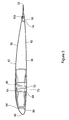
- FIGS 2 and 3 show a distal end portion of a helicopter main rotor blade 42 incorporating the adjustable weight system of the invention.
- the weight adjustable system is described as being attached to a composite material rotor blade 42 of a helicopter.
- the weight adjustable system of the invention may be employed in other operative environments, and the environment of the composite material helicopter rotor blade 42 used herein is illustrative only and should not be interpreted as limiting.
- the rotor blade 42 has a construction that is typical of composite material rotor blades.
- the blade 42 has a longitudinal length with opposite proximal 44 and distal 46 ends.
- the blade 42 has a lateral width between a leading edge 48 and a trailing edge 52 of the blade. As best seen in Figure 3, the thickness of the rotor blade 42 decreases as it extends from the leading edge 48 to the trailing edge 52.
- a tubular spar 54 extends longitudinal through the interior of the rotor blade along the rotor blade length.
- a core material 56 fills a portion of the rotor blade interior in front of the spar 54 and fills a portion of the rotor blade interior behind the spar. As best seen in Figure 3, the core material 56 behind the rotor blade spar 54 tapers as it extends to the rotor blade trailing edge 52.
- the exterior surfaces of the rotor blade are constructed of layers of composite material.
- One or more layers of the composite material form the upper surface 58 of the rotor blade and the lower surface 62 of the rotor blade.
- a forward weight pocket 64 is formed in the lower surface 62 of the rotor blade adjacent the rotor blade leading edge 48.
- the forward weight pocket 64 is constructed as prior art forward weight pockets and includes a metal sidewall having an oblong shape.
- the weight pocket sidewall 64 extends into the interior of the rotor blade tubular spar 54.
- a plurality of fastener posts 66 are positioned along the center line of the forward weight pocket 64.
- a forward weight 68 having a shape complementary to that of the forward weight pocket sidewall 64, is positioned inside the pocket sidewall.
- a plurality of threaded fasteners 72 secure the weight 68 in the interior of the forward pocket sidewall 64.
- a cover plate 70 is secured over the forward weight pocket 64 and the forward weight 68 by threaded fasteners (not shown), as is conventional in the prior art.
- the construction of the forward pocket 64 of the invention shown in Figure 3 differs from that of the prior art in that only a single weight 68 is secured in the pocket. This eliminates the second, forward weight of the prior art, and its associated manufacturing and assembly costs.
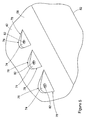
- a plurality of depressions or aft recesses 74 are formed into the composite material layers of the rotor blade lower surface 62 adjacent the blade trailing edge 52.
- three aft recesses 74 are formed in the rotor blade.
- Each of the aft recesses 74 has the same aerodynamic, triangular configuration.
- An apex area 76 of each recess is positioned in a forward area of the recess toward the rotor blade leading edge 48.
- a wider, base area 78 of each recess is positioned in the recess toward the rotor blade trailing edge 52.
- Each recess 74 has a greater depth dimension toward the apex area 76 of the recess, as seen in Figures 3 and 5. As each recess 74 extends laterally from the apex area 76 toward the base area 78 and the rotor blade trailing edge 52, the thickness of the recess tapers and decreases.
- a fastener hole 82 is positioned in a central portion of each aft recess 74.
- the fastener hole 82 extends completely through the rotor blade 42 adjacent the rotor blade trailing edge 52.
- the system of the invention also comprises a plurality of aft weights 92, 92' that are removably attached in the aft recesses 74 of the rotor blade 42. Examples of two of the aft weights 92, 92' of the invention are shown in Figures 7a and 7b.
- Each of the aft weights 92, 92' is comprised of a body 94, 94', preferably of a plastic material, and a metallic core 96, 96'. Other types of materials may be employed in constructing the core 96, 96', with the material of the core primarily providing the weight to the aft weight 92, 92'.
- Each aft weight body 94, 94' has an aerodynamic, triangular configuration that is dimensioned to closely match the configuration of one of the aft recesses 74.
- the aft weight body 94, 94' is formed with an apex portion 98, 98' that is received in the apex area 76 of an aft recess, and a base portion 102, 102' that is received in the base area 78 of the recess.
- the exterior configurations of the aft weights are substantially the same.
- Each of the aft weight cores 96, 96' has an internally threaded screw hole 104.
- the screw hole 104 is positioned on the weight where it will align with the fastener hole 82 of the aft recess 74 in which the aft weight is positioned.
- the plurality of aft weights 92, 92' differ from each other in the different sizes and masses of the weight cores 96, 96', as shown in Figures 7a and 7b.
- a threaded fastener 106 can be inserted through the recess fastener hole 82 and screw threaded into the aft weight fastener hole 104 in removably attaching the weight to the rotor blade trailing edge 52.
- the exterior surface of the aft weight is flush with the rotor blade lower surface 62. In this manner, the weight of the rotor blade 42 can be adjusted and balanced without appreciably altering the aerodynamics of the rotor blade.
Landscapes
- Engineering & Computer Science (AREA)
- Mechanical Engineering (AREA)
- Aviation & Aerospace Engineering (AREA)
- Toys (AREA)
- Turbine Rotor Nozzle Sealing (AREA)
- Wind Motors (AREA)
- Structures Of Non-Positive Displacement Pumps (AREA)
Applications Claiming Priority (2)
| Application Number | Priority Date | Filing Date | Title |
|---|---|---|---|
| US847006 | 2004-05-17 | ||
| US10/847,006 US7118343B2 (en) | 2004-05-17 | 2004-05-17 | Trailing edge adjustable weight system for helicopter main rotor blades |
Publications (3)
| Publication Number | Publication Date |
|---|---|
| EP1598269A2 true EP1598269A2 (de) | 2005-11-23 |
| EP1598269A3 EP1598269A3 (de) | 2015-03-04 |
| EP1598269B1 EP1598269B1 (de) | 2016-12-28 |
Family
ID=34938276
Family Applications (1)
| Application Number | Title | Priority Date | Filing Date |
|---|---|---|---|
| EP05076137.8A Expired - Lifetime EP1598269B1 (de) | 2004-05-17 | 2005-05-17 | Einstellbares Hinterkantengewichtssystem für Hubschrauberrotorblätter |
Country Status (3)
| Country | Link |
|---|---|
| US (1) | US7118343B2 (de) |
| EP (1) | EP1598269B1 (de) |
| ES (1) | ES2610393T3 (de) |
Cited By (2)
| Publication number | Priority date | Publication date | Assignee | Title |
|---|---|---|---|---|
| EP2711293A3 (de) * | 2012-09-25 | 2017-11-01 | The Boeing Company | Gehäuse mit einstellbarer Nutzlast für Flügel |
| EP3437991A1 (de) * | 2017-08-02 | 2019-02-06 | Bell Helicopter Textron Inc. | Rotorlängenauswuchttasche |
Families Citing this family (15)
| Publication number | Priority date | Publication date | Assignee | Title |
|---|---|---|---|---|
| US8029240B2 (en) * | 2007-11-08 | 2011-10-04 | The Boeing Company | Rotor blade adjustable weight retention system |
| EP2123556B1 (de) * | 2008-05-22 | 2010-12-08 | Agusta S.p.A. | Drehmomentausgleichs-Heckrotorblatt für Hubschrauber |
| US8192162B2 (en) * | 2008-07-29 | 2012-06-05 | Loftus Robert T | Field installable and removable helicopter rotor blade vibration and blade tracking device |
| US8668285B2 (en) * | 2008-08-13 | 2014-03-11 | Becklin Holdings, Inc. | Systems and method for securing electronics equipment |
| US9914533B2 (en) * | 2013-12-05 | 2018-03-13 | Sikorsky Aircraft Corporation | In-wing device retention |
| EP3233630B1 (de) * | 2014-12-19 | 2019-09-18 | Sikorsky Aircraft Corporation | Flugzeugrotorschaufel mit reduzierter spannung |
| WO2017048683A1 (en) * | 2015-09-17 | 2017-03-23 | Sikorsky Aircraft Corporation | Stress reducing holes |
| US10239604B2 (en) * | 2016-05-21 | 2019-03-26 | Bell Helicopter Textron Inc. | Structurally biased proprotor blade assembly |
| US11254424B2 (en) * | 2019-09-30 | 2022-02-22 | Textron Innovations Inc. | Balance weight assemblies for rotor blades |
| CH717385A1 (de) * | 2020-05-06 | 2021-11-15 | Kopter Group Ag | Heckrotorkopf eines ummantelten Heckrotors eines Drehflügelflugzeugs und Blatthalterung. |
| US12006026B2 (en) | 2020-07-10 | 2024-06-11 | Haymatt, L.L.C. | Sound-reducing rotor blade tracking wedge profile |
| US12589863B1 (en) | 2021-07-07 | 2026-03-31 | Haymatt, L.L.C. | Sound-reducing rotor blade tracking wedge profile |
| US12214872B2 (en) | 2023-04-07 | 2025-02-04 | Lockheed Martin Corporation | Tip end joint arrangement for a rotor blade with reconfigurable attributes for structural and aerodynamic tuning |
| US12497166B2 (en) | 2023-04-07 | 2025-12-16 | Lockheed Martin Corporation | Tip end joint arrangement for a rotor blade with reconfigurable attributes for structural and aerodynamic tuning |
| US12491986B2 (en) * | 2023-12-19 | 2025-12-09 | Textron Innovations Inc. | Inertial weight system for main rotor blades |
Family Cites Families (6)
| Publication number | Priority date | Publication date | Assignee | Title |
|---|---|---|---|---|
| US3999888A (en) * | 1975-06-25 | 1976-12-28 | United Technologies Corporation | Composite tip weight attachment |
| US4601639A (en) * | 1984-03-19 | 1986-07-22 | Bell Helicopter Textron Inc. | Nodalized rotor |
| GB2327926B (en) * | 1987-06-26 | 1999-06-02 | Aerospatiale | Blade with a weak radar signature |
| US6139271A (en) * | 1998-03-17 | 2000-10-31 | Chadwick-Helmuth Company, Inc. | Helicopter rotor blade weighting |
| FR2784351B1 (fr) * | 1998-10-12 | 2000-12-08 | Eurocopter France | Dispositif et procede pour reduire les vibrations engendrees sur la structure d'un aeronef a voilure tournante, notamment un helicoptere |
| EP1412245B1 (de) * | 2001-08-02 | 2011-03-02 | Bell Helicopter Textron Inc. | Ausgleichsgewichthalteanordnung für hubschrauberhauptrotorblatt |
-
2004
- 2004-05-17 US US10/847,006 patent/US7118343B2/en not_active Expired - Lifetime
-
2005
- 2005-05-17 EP EP05076137.8A patent/EP1598269B1/de not_active Expired - Lifetime
- 2005-05-17 ES ES05076137.8T patent/ES2610393T3/es not_active Expired - Lifetime
Non-Patent Citations (1)
| Title |
|---|
| None |
Cited By (3)
| Publication number | Priority date | Publication date | Assignee | Title |
|---|---|---|---|---|
| EP2711293A3 (de) * | 2012-09-25 | 2017-11-01 | The Boeing Company | Gehäuse mit einstellbarer Nutzlast für Flügel |
| EP3437991A1 (de) * | 2017-08-02 | 2019-02-06 | Bell Helicopter Textron Inc. | Rotorlängenauswuchttasche |
| US10981647B2 (en) | 2017-08-02 | 2021-04-20 | Bell Helicopter Textron Inc. | Rotor span-balance pocket |
Also Published As
| Publication number | Publication date |
|---|---|
| EP1598269B1 (de) | 2016-12-28 |
| US20050254947A1 (en) | 2005-11-17 |
| ES2610393T3 (es) | 2017-04-27 |
| EP1598269A3 (de) | 2015-03-04 |
| US7118343B2 (en) | 2006-10-10 |
Similar Documents
| Publication | Publication Date | Title |
|---|---|---|
| US7118343B2 (en) | Trailing edge adjustable weight system for helicopter main rotor blades | |
| US6568632B2 (en) | Variable size blended wing body aircraft | |
| US4150920A (en) | Rotor blade tipweight assembly | |
| EP2038171B1 (de) | Flugzeug mit einem trimmbaren höhenleitwerk | |
| US9511850B2 (en) | Wing tip device for an aircraft wing | |
| US5979824A (en) | Stabilizer fins-inverted for aircraft | |
| US10183740B2 (en) | Leading edge nose structure on the vertical stabilizer of an aircraft | |
| EP2196391A2 (de) | Schlagfeste Vorderkantenstrukturen für ein Flugzeug und Flugzeug damit | |
| US20090269205A1 (en) | Main rotor blade with integral cuff | |
| US10371165B2 (en) | Fan blade composite ribs | |
| US20040138016A1 (en) | Broadhead arrowhead | |
| WO2004014726A1 (en) | Composite tail cone assembly for a helicopter | |
| US4022546A (en) | Helicopter rotor blade | |
| CN110431076A (zh) | 无尾飞机 | |
| GB2415170A (en) | Pivoting aircraft wing and associated method | |
| US7063289B2 (en) | Helicopter tail section | |
| EP3156323B1 (de) | Vorderkante für eine tragfläche | |
| JP3550104B2 (ja) | 翼の補強体 | |
| WO2007018772A3 (en) | Rotor blade assembly with high pitching moment airfoil section for a rotary wing aircraft | |
| EP4331982A1 (de) | Verfahren zur stabilisierung eines gelenkigen rotorblatts | |
| JP4402160B1 (ja) | 模型回転翼航空機の回転翼、及びその回転翼の製造方法 | |
| US9745056B2 (en) | Main rotor blade with composite integral skin and cuff | |
| CN110896626A (zh) | 螺旋桨、动力组件及飞行器 | |
| US2477113A (en) | Rotor blade for rotative winged aircraft | |
| GB2362865A (en) | Rotor for a rotary wing aircraft |
Legal Events
| Date | Code | Title | Description |
|---|---|---|---|
| PUAI | Public reference made under article 153(3) epc to a published international application that has entered the european phase |
Free format text: ORIGINAL CODE: 0009012 |
|
| AK | Designated contracting states |
Kind code of ref document: A2 Designated state(s): AT BE BG CH CY CZ DE DK EE ES FI FR GB GR HU IE IS IT LI LT LU MC NL PL PT RO SE SI SK TR |
|
| AX | Request for extension of the european patent |
Extension state: AL BA HR LV MK YU |
|
| PUAL | Search report despatched |
Free format text: ORIGINAL CODE: 0009013 |
|
| AK | Designated contracting states |
Kind code of ref document: A3 Designated state(s): AT BE BG CH CY CZ DE DK EE ES FI FR GB GR HU IE IS IT LI LT LU MC NL PL PT RO SE SI SK TR |
|
| AX | Request for extension of the european patent |
Extension state: AL BA HR LV MK YU |
|
| RIC1 | Information provided on ipc code assigned before grant |
Ipc: B64C 27/00 20060101ALI20150123BHEP Ipc: B64C 27/473 20060101AFI20150123BHEP |
|
| 17P | Request for examination filed |
Effective date: 20150313 |
|
| RBV | Designated contracting states (corrected) |
Designated state(s): AT BE BG CH CY CZ DE DK EE ES FI FR GB GR HU IE IS IT LI LT LU MC NL PL PT RO SE SI SK TR |
|
| AKX | Designation fees paid |
Designated state(s): AT BE BG CH CY CZ DE DK EE ES FI FR GB GR HU IE IS IT LI LT LU MC NL PL PT RO SE SI SK TR |
|
| AXX | Extension fees paid |
Extension state: BA Extension state: AL Extension state: LV Extension state: MK Extension state: YU Extension state: HR |
|
| 17Q | First examination report despatched |
Effective date: 20160118 |
|
| GRAP | Despatch of communication of intention to grant a patent |
Free format text: ORIGINAL CODE: EPIDOSNIGR1 |
|
| INTG | Intention to grant announced |
Effective date: 20160816 |
|
| GRAS | Grant fee paid |
Free format text: ORIGINAL CODE: EPIDOSNIGR3 |
|
| GRAA | (expected) grant |
Free format text: ORIGINAL CODE: 0009210 |
|
| AK | Designated contracting states |
Kind code of ref document: B1 Designated state(s): AT BE BG CH CY CZ DE DK EE ES FI FR GB GR HU IE IS IT LI LT LU MC NL PL PT RO SE SI SK TR |
|
| REG | Reference to a national code |
Ref country code: GB Ref legal event code: FG4D |
|
| REG | Reference to a national code |
Ref country code: CH Ref legal event code: EP |
|
| REG | Reference to a national code |
Ref country code: AT Ref legal event code: REF Ref document number: 857021 Country of ref document: AT Kind code of ref document: T Effective date: 20170115 |
|
| REG | Reference to a national code |
Ref country code: IE Ref legal event code: FG4D |
|
| REG | Reference to a national code |
Ref country code: DE Ref legal event code: R096 Ref document number: 602005050992 Country of ref document: DE |
|
| REG | Reference to a national code |
Ref country code: LT Ref legal event code: MG4D |
|
| REG | Reference to a national code |
Ref country code: ES Ref legal event code: FG2A Ref document number: 2610393 Country of ref document: ES Kind code of ref document: T3 Effective date: 20170427 |
|
| PG25 | Lapsed in a contracting state [announced via postgrant information from national office to epo] |
Ref country code: SE Free format text: LAPSE BECAUSE OF FAILURE TO SUBMIT A TRANSLATION OF THE DESCRIPTION OR TO PAY THE FEE WITHIN THE PRESCRIBED TIME-LIMIT Effective date: 20161228 Ref country code: LT Free format text: LAPSE BECAUSE OF FAILURE TO SUBMIT A TRANSLATION OF THE DESCRIPTION OR TO PAY THE FEE WITHIN THE PRESCRIBED TIME-LIMIT Effective date: 20161228 Ref country code: GR Free format text: LAPSE BECAUSE OF FAILURE TO SUBMIT A TRANSLATION OF THE DESCRIPTION OR TO PAY THE FEE WITHIN THE PRESCRIBED TIME-LIMIT Effective date: 20170329 |
|
| REG | Reference to a national code |
Ref country code: NL Ref legal event code: MP Effective date: 20161228 |
|
| REG | Reference to a national code |
Ref country code: AT Ref legal event code: MK05 Ref document number: 857021 Country of ref document: AT Kind code of ref document: T Effective date: 20161228 |
|
| REG | Reference to a national code |
Ref country code: FR Ref legal event code: PLFP Year of fee payment: 13 |
|
| PG25 | Lapsed in a contracting state [announced via postgrant information from national office to epo] |
Ref country code: FI Free format text: LAPSE BECAUSE OF FAILURE TO SUBMIT A TRANSLATION OF THE DESCRIPTION OR TO PAY THE FEE WITHIN THE PRESCRIBED TIME-LIMIT Effective date: 20161228 |
|
| PG25 | Lapsed in a contracting state [announced via postgrant information from national office to epo] |
Ref country code: NL Free format text: LAPSE BECAUSE OF FAILURE TO SUBMIT A TRANSLATION OF THE DESCRIPTION OR TO PAY THE FEE WITHIN THE PRESCRIBED TIME-LIMIT Effective date: 20161228 |
|
| PG25 | Lapsed in a contracting state [announced via postgrant information from national office to epo] |
Ref country code: SK Free format text: LAPSE BECAUSE OF FAILURE TO SUBMIT A TRANSLATION OF THE DESCRIPTION OR TO PAY THE FEE WITHIN THE PRESCRIBED TIME-LIMIT Effective date: 20161228 Ref country code: RO Free format text: LAPSE BECAUSE OF FAILURE TO SUBMIT A TRANSLATION OF THE DESCRIPTION OR TO PAY THE FEE WITHIN THE PRESCRIBED TIME-LIMIT Effective date: 20161228 Ref country code: EE Free format text: LAPSE BECAUSE OF FAILURE TO SUBMIT A TRANSLATION OF THE DESCRIPTION OR TO PAY THE FEE WITHIN THE PRESCRIBED TIME-LIMIT Effective date: 20161228 Ref country code: CZ Free format text: LAPSE BECAUSE OF FAILURE TO SUBMIT A TRANSLATION OF THE DESCRIPTION OR TO PAY THE FEE WITHIN THE PRESCRIBED TIME-LIMIT Effective date: 20161228 Ref country code: IS Free format text: LAPSE BECAUSE OF FAILURE TO SUBMIT A TRANSLATION OF THE DESCRIPTION OR TO PAY THE FEE WITHIN THE PRESCRIBED TIME-LIMIT Effective date: 20170428 |
|
| PG25 | Lapsed in a contracting state [announced via postgrant information from national office to epo] |
Ref country code: BG Free format text: LAPSE BECAUSE OF FAILURE TO SUBMIT A TRANSLATION OF THE DESCRIPTION OR TO PAY THE FEE WITHIN THE PRESCRIBED TIME-LIMIT Effective date: 20170328 Ref country code: LU Free format text: LAPSE BECAUSE OF NON-PAYMENT OF DUE FEES Effective date: 20170531 Ref country code: PL Free format text: LAPSE BECAUSE OF FAILURE TO SUBMIT A TRANSLATION OF THE DESCRIPTION OR TO PAY THE FEE WITHIN THE PRESCRIBED TIME-LIMIT Effective date: 20161228 Ref country code: BE Free format text: LAPSE BECAUSE OF FAILURE TO SUBMIT A TRANSLATION OF THE DESCRIPTION OR TO PAY THE FEE WITHIN THE PRESCRIBED TIME-LIMIT Effective date: 20161228 Ref country code: AT Free format text: LAPSE BECAUSE OF FAILURE TO SUBMIT A TRANSLATION OF THE DESCRIPTION OR TO PAY THE FEE WITHIN THE PRESCRIBED TIME-LIMIT Effective date: 20161228 |
|
| REG | Reference to a national code |
Ref country code: DE Ref legal event code: R097 Ref document number: 602005050992 Country of ref document: DE |
|
| PLBE | No opposition filed within time limit |
Free format text: ORIGINAL CODE: 0009261 |
|
| STAA | Information on the status of an ep patent application or granted ep patent |
Free format text: STATUS: NO OPPOSITION FILED WITHIN TIME LIMIT |
|
| PG25 | Lapsed in a contracting state [announced via postgrant information from national office to epo] |
Ref country code: DK Free format text: LAPSE BECAUSE OF FAILURE TO SUBMIT A TRANSLATION OF THE DESCRIPTION OR TO PAY THE FEE WITHIN THE PRESCRIBED TIME-LIMIT Effective date: 20161228 |
|
| 26N | No opposition filed |
Effective date: 20170929 |
|
| REG | Reference to a national code |
Ref country code: CH Ref legal event code: PL |
|
| PG25 | Lapsed in a contracting state [announced via postgrant information from national office to epo] |
Ref country code: MC Free format text: LAPSE BECAUSE OF FAILURE TO SUBMIT A TRANSLATION OF THE DESCRIPTION OR TO PAY THE FEE WITHIN THE PRESCRIBED TIME-LIMIT Effective date: 20161228 |
|
| REG | Reference to a national code |
Ref country code: IE Ref legal event code: MM4A |
|
| PG25 | Lapsed in a contracting state [announced via postgrant information from national office to epo] |
Ref country code: LI Free format text: LAPSE BECAUSE OF NON-PAYMENT OF DUE FEES Effective date: 20170531 Ref country code: CH Free format text: LAPSE BECAUSE OF NON-PAYMENT OF DUE FEES Effective date: 20170531 Ref country code: SI Free format text: LAPSE BECAUSE OF FAILURE TO SUBMIT A TRANSLATION OF THE DESCRIPTION OR TO PAY THE FEE WITHIN THE PRESCRIBED TIME-LIMIT Effective date: 20161228 |
|
| PG25 | Lapsed in a contracting state [announced via postgrant information from national office to epo] |
Ref country code: LU Free format text: LAPSE BECAUSE OF NON-PAYMENT OF DUE FEES Effective date: 20170517 |
|
| PG25 | Lapsed in a contracting state [announced via postgrant information from national office to epo] |
Ref country code: IE Free format text: LAPSE BECAUSE OF NON-PAYMENT OF DUE FEES Effective date: 20170517 |
|
| REG | Reference to a national code |
Ref country code: FR Ref legal event code: PLFP Year of fee payment: 14 |
|
| PG25 | Lapsed in a contracting state [announced via postgrant information from national office to epo] |
Ref country code: HU Free format text: LAPSE BECAUSE OF FAILURE TO SUBMIT A TRANSLATION OF THE DESCRIPTION OR TO PAY THE FEE WITHIN THE PRESCRIBED TIME-LIMIT; INVALID AB INITIO Effective date: 20050517 |
|
| PG25 | Lapsed in a contracting state [announced via postgrant information from national office to epo] |
Ref country code: CY Free format text: LAPSE BECAUSE OF NON-PAYMENT OF DUE FEES Effective date: 20161228 |
|
| REG | Reference to a national code |
Ref country code: DE Ref legal event code: R082 Ref document number: 602005050992 Country of ref document: DE Representative=s name: MAIER, LL.M., MICHAEL C., DE Ref country code: DE Ref legal event code: R082 Ref document number: 602005050992 Country of ref document: DE Representative=s name: BOULT WADE TENNANT LLP, DE |
|
| REG | Reference to a national code |
Ref country code: DE Ref legal event code: R082 Ref document number: 602005050992 Country of ref document: DE Representative=s name: BOULT WADE TENNANT LLP, DE |
|
| PG25 | Lapsed in a contracting state [announced via postgrant information from national office to epo] |
Ref country code: PT Free format text: LAPSE BECAUSE OF FAILURE TO SUBMIT A TRANSLATION OF THE DESCRIPTION OR TO PAY THE FEE WITHIN THE PRESCRIBED TIME-LIMIT Effective date: 20161228 |
|
| P01 | Opt-out of the competence of the unified patent court (upc) registered |
Effective date: 20230503 |
|
| PGFP | Annual fee paid to national office [announced via postgrant information from national office to epo] |
Ref country code: GB Payment date: 20240527 Year of fee payment: 20 |
|
| PGFP | Annual fee paid to national office [announced via postgrant information from national office to epo] |
Ref country code: DE Payment date: 20240530 Year of fee payment: 20 |
|
| PGFP | Annual fee paid to national office [announced via postgrant information from national office to epo] |
Ref country code: ES Payment date: 20240603 Year of fee payment: 20 |
|
| PGFP | Annual fee paid to national office [announced via postgrant information from national office to epo] |
Ref country code: FR Payment date: 20240527 Year of fee payment: 20 |
|
| PGFP | Annual fee paid to national office [announced via postgrant information from national office to epo] |
Ref country code: TR Payment date: 20240503 Year of fee payment: 20 |
|
| PGFP | Annual fee paid to national office [announced via postgrant information from national office to epo] |
Ref country code: IT Payment date: 20240521 Year of fee payment: 20 |
|
| REG | Reference to a national code |
Ref country code: DE Ref legal event code: R071 Ref document number: 602005050992 Country of ref document: DE |
|
| REG | Reference to a national code |
Ref country code: ES Ref legal event code: FD2A Effective date: 20250526 |
|
| REG | Reference to a national code |
Ref country code: GB Ref legal event code: PE20 Expiry date: 20250516 |
|
| PG25 | Lapsed in a contracting state [announced via postgrant information from national office to epo] |
Ref country code: ES Free format text: LAPSE BECAUSE OF EXPIRATION OF PROTECTION Effective date: 20250518 Ref country code: GB Free format text: LAPSE BECAUSE OF EXPIRATION OF PROTECTION Effective date: 20250516 |