EP1598663A2 - Procédé et appareil d'analyse aux rayons X avec un Réseau de détecteurs bidemensionnel - Google Patents
Procédé et appareil d'analyse aux rayons X avec un Réseau de détecteurs bidemensionnel Download PDFInfo
- Publication number
- EP1598663A2 EP1598663A2 EP05009958A EP05009958A EP1598663A2 EP 1598663 A2 EP1598663 A2 EP 1598663A2 EP 05009958 A EP05009958 A EP 05009958A EP 05009958 A EP05009958 A EP 05009958A EP 1598663 A2 EP1598663 A2 EP 1598663A2
- Authority
- EP
- European Patent Office
- Prior art keywords
- detector
- data set
- pixel
- source
- data sets
- Prior art date
- Legal status (The legal status is an assumption and is not a legal conclusion. Google has not performed a legal analysis and makes no representation as to the accuracy of the status listed.)
- Granted
Links
Images


Classifications
-
- G—PHYSICS
- G01—MEASURING; TESTING
- G01N—INVESTIGATING OR ANALYSING MATERIALS BY DETERMINING THEIR CHEMICAL OR PHYSICAL PROPERTIES
- G01N23/00—Investigating or analysing materials by the use of wave or particle radiation, e.g. X-rays or neutrons, not covered by groups G01N3/00 – G01N17/00, G01N21/00 or G01N22/00
- G01N23/20—Investigating or analysing materials by the use of wave or particle radiation, e.g. X-rays or neutrons, not covered by groups G01N3/00 – G01N17/00, G01N21/00 or G01N22/00 by using diffraction of the radiation by the materials, e.g. for investigating crystal structure; by using scattering of the radiation by the materials, e.g. for investigating non-crystalline materials; by using reflection of the radiation by the materials
- G01N23/207—Diffractometry using detectors, e.g. using a probe in a central position and one or more displaceable detectors in circumferential positions
Definitions
- the invention relates to a method for operating an X-ray analysis device with a source of x-radiation, an object to be examined, which coincides with the X-ray is illuminated, and a two-dimensional planar array detector with pixel elements for spatially resolved detection of the object outgoing X-rays, creating a record, especially in shape a digitized diffractogram and / or spectrum is obtained.
- the invention relates to an X-ray analysis apparatus for performing the Process.
- Two-dimensional array detectors used in X-ray analyzers of the above mentioned type are among others from Gerhard Lutz "Semiconductor radiation detectors ", B. Mikulec et al.” Development of Segmented Semiconductor Arrays for Quantum Imaging "Elsevier Science, N. Wermes” Pixel detectors for particle physics and imaging applications "Elsevier Science Direct and Edwin M. Westbrook's National Institute of Health grant application www.brunel.ac.uk/research/rose/3D/publications.html known. Such an array Detectors consist of a large number of photosensitive pixel elements, which in Form of an array are arranged on a chip.
- the sensor chip is for usually by bump bonding with an ASIC (Application Specific Circuit) which includes electronic channels, amplifiers and discriminators.
- ASIC Application Specific Circuit
- the photosensitive pixel elements are fixedly connected to the ASIC and a Replacing a defective pixel element is not possible, make erroneous, especially blind pixel elements is a big technical problem. It will while trying to figure out the number of blind pixel elements To reduce manufacturing improvement, due to the great complexity of However, hybrid production (sensor, bump bonds, highly integrated ASIC) will be hampered For the foreseeable future, only very expensive 100% functioning pixel detectors will be available. For therefore, one usually takes the presence of isolated blind people Pixel elements and the resulting missing information in the corresponding areas in purchase.
- one-dimensional detectors are known (H. Göbel, Adv. In X-Ray Analysis 22 (1978) 255-265), which are moved by means of a goniometer by changing the 20 value over the range of interest for the measurement so that certain ranges can be detected by different pixels. With this method, however, only one-dimensional recordings are possible. Furthermore, in such an arrangement, the optics for focusing the radiation on the detector must be moved with the detector, which requires a complex and particularly stable construction of the structure.
- Object of the present invention is therefore to provide a method for operating a X-ray analysis device with a two-dimensional array detector with pixel elements to propose that, despite the presence of blind pixel elements in the detector to reduce the number of dead pixels in the record or to avoid and as complete a record as possible to obtain. Furthermore, an X-ray analysis device is to be proposed, with which this method can be carried out.
- Step d) the steps b) to c) with varying displacement once or several times repeated. This allows the number of dead pixels in the record to be arbitrary be reduced.
- a development of this variant provides that the data records during a continuous, preferably periodic displacement and / or rotation of the Detector be recorded.
- the total data set then includes the integrated data between two positions of the detector.
- the detector therefore becomes between two shots of consecutive records by exactly one Moved pixel element.
- a further object of the invention is a method for operating an X-ray analysis device to propose that the measurement of a record with a Resolution greater than the dimensions of each pixel element.
- a further variant of the method according to the invention therefore provides that the detector is shifted by a fraction, preferably 1 / n, of a pixel element between two recordings of successive data records, where n ⁇ N, preferably n ⁇ 10 Detector to a subpixel, the spatial resolution can be increased. This is particularly advantageous for detectors with large pixel elements or for the recording of very small structures. The resolution of the detector is thereby improved so that structures within a pixel element can be detected. In order to obtain a uniform resolution over the entire detector range, n shifts must be carried out with the corresponding recordings.
- the displacements of the Detector different directions in the detector surface.
- the postponement of the detector can then be done within the entire area of the detector, so that optimization with respect to the position of the dead pixels is simplified.
- step d) the pixels of the border areas of the entire record, which does not include the records of all individual recordings weighted according to the inverse of their admission frequency become. For each pixel then results in a mean signal intensity.
- Each pixel element is individually a sensitivity and / or a statistical Associated error and / or offset for the recorded reading, in step d) in a weighting of the respective pixel in the overlay taken into account.
- the shots of the individual Data sets are thus not affected by the varying sensitivity and / or falsified the statistical error or offset.
- the superimposition of the recorded individual data sets is preferably carried out such that for each of the data points to be overlaid the offset is subtracted, the measured value according to the sensitivity of the respective pixel element normalized and inversely weighted to the size of the associated statistical error where the overall weighting for each pixel is 1 or 100%.
- the contributions are individual Pixel elements in the overlay of the data records in step d) fixed with 0 weighted, especially with defective pixel elements, which are known that they are blind, generate strongly fluctuating signals or constantly their saturation value Show. Due to the strong distorting effects of such Pixel elements, it seems advantageous to weight these with 0 and the values of the corresponding pixels for the entire data set from the remaining data sets to win.
- each pixel must be at least once taken by a non-0 pixel element. It is therefore advantageous, the trajectories of the respective shifts to the spatial Adjust the distribution of defective pixel elements, especially such that as far as possible no data point of the entire data set exclusively the superposition of signal contributions of defective pixel elements.
- the detector several each over blind border areas adjacent to each other Sensor chips is composed, and that the blind edge areas like damaged pixel elements are treated.
- such composite detectors have many non-photosensitive areas is it is possible by the inventive method, total data sets which does not have holes due to the lack of active pixel elements have the corresponding edge regions of the sensor chips.
- the trajectories of the respective shifts are chosen that the overall statistical error of the entire data set is minimized. On This way, dead pixels or 0 weighted pixels on as possible distributed many different positions and avoided double-blind measurements become.
- the X-ray analysis apparatus is for carrying out the previously described Set up procedure.
- An advantageous embodiment of the X-ray analysis device provides a piezo drive to move the detector.
- a piezo drive Shifts on ⁇ m scale and below are realizable, so that almost Any shifts of the detector are possible.
- a further embodiment of the X-ray analysis device provides that the Array detector along with a first stage of evaluation electronics a carrier which is not moved during the measurement is movably arranged, the first stage via a flexible connection with another stage of the Evaluation electronics for signal transmission is electrically connected. To this Way, a fast preamplifier can be attached very close to the detector, resulting in an improvement of the signal-to-noise ratio. The flexible connection of the first stage with another stage of the evaluation electronics the mobility of the detector is ensured.
- a development of the X-ray analysis device according to the invention provides that the flexible connection a thin film, preferably a polyimide film with integrated Includes printed conductors.
- the width B of the blind edge regions is an integer multiple of Width b of a pixel element. Due to the non-sensitive edge areas in the first single data record missing data points can then by a shift of the detector to obtain an integer number of pixel elements become.
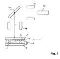
- Fig. 1 shows schematically the essential elements of an X-ray analysis device.
- the X-radiation emitted by a source 17 is modified by means of optical elements 18 and exposes an object 19 of special X-radiation.
- the X-ray beam is focused onto the detector by means of optical elements 18.
- the array detector is equipped with an X-ray sensitive single detector 1 , a first stage 2 of an evaluation (ASIC), a carrier 3 and a piezo drive 4 , wherein the single detector 1 is contacted by bumps 5 with the first stage 2 of the transmitter and firmly connected.
- ASIC evaluation
- the connection between the single detector 1 and the carrier 3 is realized by means of a flexible connection 6 , which includes electrical connections from the first stage 2 of the transmitter to a further stage of the transmitter, which may be located, for example, on the carrier 3.
- a flexible connection 6 which includes electrical connections from the first stage 2 of the transmitter to a further stage of the transmitter, which may be located, for example, on the carrier 3.
- the mass of the components to be moved is kept low, so that the shift can be done quickly and easily by using a piezoelectric drive 4, on the other hand, by the Mitverschieben the first stage 2 of the evaluation a low noise preamplification and first digital processing of the detected signals take place and thus a good signal / noise ratio can be achieved.
- the displacement of the single detector 1 takes place in one or in two dimensions such that the radial distance r of the single detector 1 to the object 19 does not change. The movement is indicated by the arrow. Thus, there is no need to focus on a new level.
- the single detector 1 of Fig. 1 is shown here in a planar design. However, it is also conceivable to provide curved embodiments.
- the X-ray sensitive pixel elements 7 (!!! is not marked in any drawing !!!) of the single detector 1 are typically made of Si or other semiconductor materials such as GaAs, CdTe, CZT.
- the transmitter 2 is typically implemented in CMOS or Bi-CMOS technology, eg in 0.35 ⁇ m feature sizes.
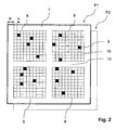
- FIG. 1 An overall detector 1 is shown in FIG . Since the individual sensor chips 8 , which are usually produced, are generally smaller than the desired single detector area, the single detector 1 is composed of a plurality of sensor chips 8. However, this has the consequence that, in addition to the defective pixel elements 9 contained in the sensor chips 8, edge regions 10 of the sensor chips 8 are additionally located within the individual detector area, from which information for the data record to be recorded can not be taken. Both the defective pixel elements 9 and the edge regions 10 of the sensor chips 8 therefore produce dead pixels 12 a, 12 b in a recorded data record 11 . In order to avoid distortions of information within a data set 11, defective pixel elements 9 in the data set are weighted with 0.
- blind pixel elements these also include pixel elements that generate strongly fluctuating signals or constantly reach their saturation value. Such pixel elements can be located by a 0-measurement.
- Common sensor chips include about 1,000 x 1,000 pixel elements. For the sake of simplicity, the sensor chips 8 shown in FIG. 2 have been shown with only 10 x 10 pixel elements.
- FIG. 3a shows a schematic representation of the distribution of dead pixels 12a, 12b in a data record 11, which was recorded by a single detector 1, as shown in FIG.
- the isolated dead pixels 12a which result from the defective pixel elements 9 of the single detector 1
- this is impractical if the radiation to be detected has to be focused on a specific plane, as is required, for example, in Bragg-Brentano geometry in X-ray diffractometry.
- the sensor chips 8 are therefore arranged in a plane.
- the single detector 1 is moved after a first recording of a first data set in a position P1 from this position P1 to a position P2, as shown in Fig. 2.
- a further data record 11 is recorded, which is superimposed with the first data record 11, so that a total data record 13 is formed.
- the width B of the blind edge regions of the sensor chips 8 in the method according to the invention is preferably an integer multiple of the width b of a pixel element, the width b of a pixel element moving in the order of 50 to 100 ⁇ m. In this way, it is possible to completely coincide a pixel element in position P1 with a pixel element in position P2 by shifting the single detector 1 by an integer multiple of a pixel element 7.
- Fig. 3b shows the distribution of the dead pixels 12 in the total data set 13, which is obtained from the data sets 11 of the measurements in the positions P1 and P2.
- the shift of the single detector 1 is chosen arbitrarily here and was 2x2 pixel elements. It can be seen from the overall data set 13 that the number of dead pixels 12 compared to the number of dead pixels 12a, 12b in the data set 11 of FIG. 3 is considerably reduced. With a suitable optimization of the displacement of the individual detector 1, a further reduction of the dead pixels 12 in the overall data set 13 can be achieved, ideally zero dead pixels 12. Likewise, the result by recording more records 11 in different positions of the single detector 1 and their superposition an overall data record 13 can be improved.
- the predetermined measurement time can be selected long enough for the recordings of the individual data records 11 to be made.
- XRD X-Ray Diffraction
- the different sensitivities of the individual pixel elements 7 become by a weighting of the individual pixels when superimposing the individual data sets considered.
- every pixel element can have a statistical error as well as an offset for the recorded measured value, which are stored in the Weighting of the respective pixel when superimposing the recorded data sets 11 be taken into account. This is for the data points to be overlaid in each case the offset is subtracted, the measured value according to the sensitivity of the respective pixel element 7 normalized and inversely to the size of the associated Statistical error is weighted, so for each pixel the overall weighting 1 or 100% results.
- sensor chips which have larger pixel elements in their edge regions (superpixel elements). These superpixel elements cause the resolution in these areas to be reduced. By means of the method according to the invention, this unpleasant effect can also be eliminated since, with a suitable displacement of the sensor chips 8, the areas which were previously measured by the superpixel elements are measured by a photosensitive pixel element 15 during at least one further measurement. This results in a more homogeneous spatial resolution over the entire detector surface.
- Fig. 4 this is shown schematically.
- a roughly structured rectangular single detector 8 is shifted diagonally to a position P2 (thin frame) around a sub-pixel element, in this case by half of a pixel element 7, after recording a first data set in a position P1 (bold frame). In this way, changes in the signal within a pixel can be detected, thereby increasing the spatial resolution of the entire data set.
- the advantages of the invention are particularly effective if one or several shifts by an integer multiple of a pixel element. 7 with one or more subsequent shifts by one subpixel be combined with each other. In this way one obtains using a conventional single detector 1 a total data set with a reduced number of dead pixels 12, ideally zero, and improved Spatial resolution.
- the application of the method according to the invention is not limited to rectangular sensor chips 8.
- Radially symmetrical sensor chips 14 with ring segments as pixel elements, as shown in FIG. 5 can also be used for this method.
- the displacement here takes place preferably in the form of a rotational movement about the midpoint of the radially symmetrical individual detector 14. For the calculation or optimization of the displacement, it makes sense to use polar coordinates in such radially symmetrical sensor chips.
- the defective or weighted with 0 pixel elements 9 are moved to adjacent squares 16 , so that the dead pixels of the first record in the second record by fotosenisitver pixel elements 15 are measured and thus constructively contribute to the overall data set.
- the X-ray analysis apparatus or the invention Method for operating an X-ray analyzer enabled simple way, in particular without displacement of the X-ray analyzer belonging to optical elements, a reduction of due to defective or dead pixels in the data set resulting from 0 weighted pixel elements.
- a reduction of due to defective or dead pixels in the data set resulting from 0 weighted pixel elements when using from multiple sensor chips composite single detector disturbing influences of the edge areas in the Creation of records are avoided.
Landscapes
- Chemical & Material Sciences (AREA)
- Crystallography & Structural Chemistry (AREA)
- Physics & Mathematics (AREA)
- Health & Medical Sciences (AREA)
- Life Sciences & Earth Sciences (AREA)
- Analytical Chemistry (AREA)
- Biochemistry (AREA)
- General Health & Medical Sciences (AREA)
- General Physics & Mathematics (AREA)
- Immunology (AREA)
- Pathology (AREA)
- Analysing Materials By The Use Of Radiation (AREA)
- Measurement Of Radiation (AREA)
Applications Claiming Priority (2)
| Application Number | Priority Date | Filing Date | Title |
|---|---|---|---|
| DE102004025121A DE102004025121A1 (de) | 2004-05-21 | 2004-05-21 | Verfahren zum Betrieb eines Röntgenanalysegeräts mit zweidimensionalem Array-Detektor und Röntgenanalysegerät zum Durchführen des Verfahrens |
| DE102004025121 | 2004-05-21 |
Publications (3)
| Publication Number | Publication Date |
|---|---|
| EP1598663A2 true EP1598663A2 (fr) | 2005-11-23 |
| EP1598663A3 EP1598663A3 (fr) | 2007-09-19 |
| EP1598663B1 EP1598663B1 (fr) | 2008-12-24 |
Family
ID=34936239
Family Applications (1)
| Application Number | Title | Priority Date | Filing Date |
|---|---|---|---|
| EP05009958A Expired - Lifetime EP1598663B1 (fr) | 2004-05-21 | 2005-05-06 | Procédé et appareil d'analyse aux rayons X avec un Réseau de détecteurs bidemensionnel |
Country Status (3)
| Country | Link |
|---|---|
| US (1) | US7136454B2 (fr) |
| EP (1) | EP1598663B1 (fr) |
| DE (2) | DE102004025121A1 (fr) |
Cited By (1)
| Publication number | Priority date | Publication date | Assignee | Title |
|---|---|---|---|---|
| EP3569148A1 (fr) * | 2018-05-17 | 2019-11-20 | Siemens Healthcare GmbH | Procédé d'enregistrement d'un ensemble de données d'image au moyen d'un détecteur de rayons x |
Families Citing this family (26)
| Publication number | Priority date | Publication date | Assignee | Title |
|---|---|---|---|---|
| EP1978875B1 (fr) * | 2006-01-16 | 2019-07-10 | Koninklijke Philips N.V. | Module intelligent de détecteurs de rayonnement |
| US7920676B2 (en) * | 2007-05-04 | 2011-04-05 | Xradia, Inc. | CD-GISAXS system and method |
| DE102007042144A1 (de) * | 2007-09-05 | 2009-03-12 | Smiths Heimann Gmbh | Verfahren zur Verbesserung der Materialerkennbarkeit in einer Röntgenprüfanlage und Röntgenprüfanlage |
| KR100923097B1 (ko) * | 2008-01-15 | 2009-10-22 | (주)이우테크놀로지 | X선 촬영장치 |
| US8265369B2 (en) * | 2009-04-16 | 2012-09-11 | Apteryx, Inc. | Apparatus and method for virtual flaw removal from X-ray sensitive plates |
| US20100303208A1 (en) * | 2009-05-29 | 2010-12-02 | Oliver Baruth | Method for recording an x-ray image, x-ray detector and x-ray system |
| JP5534756B2 (ja) * | 2009-09-16 | 2014-07-02 | キヤノン株式会社 | 画像処理装置、画像処理方法、画像処理システム及びプログラム |
| RU2423026C1 (ru) * | 2010-03-09 | 2011-06-27 | Общество с ограниченной ответственностью "Научно-производственное предприятие ВЭЛИТ" | Устройство для облучения объектов рентгеновскими лучами |
| EP2675358B1 (fr) * | 2011-02-17 | 2016-11-09 | Analogic Corporation | Mosaïque de détecteurs possédant une dimension utile supérieure à la dimension réelle |
| US10247682B2 (en) | 2013-04-04 | 2019-04-02 | Illinois Tool Works Inc. | Helical computed tomography |
| JP6105806B2 (ja) | 2013-04-12 | 2017-03-29 | イリノイ トゥール ワークス インコーポレイティド | 高解像度コンピュータートモグラフィー |
| US9022651B2 (en) * | 2013-07-12 | 2015-05-05 | Bruker Axs, Inc. | X-ray diffraction-based defective pixel correction method using an active pixel array sensor |
| JP6242185B2 (ja) | 2013-11-22 | 2017-12-06 | 株式会社リガク | 補正情報生成方法および補正情報生成装置 |
| JP5944369B2 (ja) * | 2013-11-26 | 2016-07-05 | 株式会社リガク | X線回折装置およびx線回折測定方法 |
| JP6135526B2 (ja) | 2014-01-30 | 2017-05-31 | 株式会社リガク | 画像処理方法および画像処理装置 |
| JP6524473B2 (ja) | 2014-10-24 | 2019-06-05 | 株式会社リガク | データ処理装置、各ピクセルの特性を求める方法ならびにデータ処理の方法およびプログラム |
| DE102015213911B4 (de) * | 2015-07-23 | 2019-03-07 | Siemens Healthcare Gmbh | Verfahren zum Erzeugen eines Röntgenbildes und Datenverarbeitungseinrichtung zum Ausführen des Verfahrens |
| DE102017205096B3 (de) * | 2017-03-27 | 2018-08-02 | Siemens Healthcare Gmbh | Akquisition von Bildern mit einem Strahlungsdetektor |
| US12281993B2 (en) | 2021-09-15 | 2025-04-22 | Illinois Tool Works Inc. | High resolution continuous rotation industrial radiography imaging processes |
| US20230316467A1 (en) * | 2022-04-05 | 2023-10-05 | Baker Hughes Holdings Llc | Digital Detector Array Correction |
| CN116893185A (zh) * | 2022-04-05 | 2023-10-17 | 贝克休斯控股有限责任公司 | 数字检测器阵列校正 |
| US12332192B2 (en) | 2022-04-20 | 2025-06-17 | Arion Diagnostics, Inc. | Alpha diffractometer |
| US12336851B2 (en) * | 2022-04-20 | 2025-06-24 | Arion Diagnostics, Inc. | Diffractive analyzer of patient tissue |
| DE102022209048A1 (de) * | 2022-08-31 | 2024-02-29 | Carl Zeiss Microscopy Gmbh | Überlappendes Pixelbinning in Kamerabildern |
| US12607578B2 (en) | 2023-06-15 | 2026-04-21 | Illinois Tool Works Inc. | Accelerated higher resolution industrial radiography |
| DE102024200530A1 (de) | 2024-01-22 | 2025-02-27 | Siemens Healthineers Ag | Röntgendetektorvorrichtung, Mehrlagenflächendetektor und Verfahren |
Family Cites Families (10)
| Publication number | Priority date | Publication date | Assignee | Title |
|---|---|---|---|---|
| US5491738A (en) * | 1993-03-15 | 1996-02-13 | The United States Of America As Represented By The Administrator Of The National Aeronautics And Space Administration | X-ray diffraction apparatus |
| US5847398A (en) | 1997-07-17 | 1998-12-08 | Imarad Imaging Systems Ltd. | Gamma-ray imaging with sub-pixel resolution |
| US6064717A (en) * | 1997-11-21 | 2000-05-16 | Rigaku/Usa, Inc. | Unrestricted motion apparatus and method for x-ray diffraction analysis |
| DE19800946A1 (de) * | 1998-01-13 | 1999-07-22 | Siemens Ag | Volumen-Computertomographiesystem |
| US6118846A (en) * | 1999-02-23 | 2000-09-12 | Direct Radiography Corp. | Bad pixel column processing in a radiation detection panel |
| DE10043474B4 (de) * | 2000-09-04 | 2007-08-09 | Siemens Ag | Detektor zum Erzeugen eines Bildes aus einfallender Strahlung |
| DE10047366A1 (de) * | 2000-09-25 | 2002-05-08 | Siemens Ag | Strahlungsdetektor |
| US6408047B1 (en) * | 2000-10-04 | 2002-06-18 | Rigaku/Msc, Inc. | Method of providing high throughput protein crystallography |
| DE10244181A1 (de) | 2002-09-23 | 2004-04-01 | Siemens Ag | Verfahren zur Bilderstellung in der Computertomographie und CT-Gerät zur Durchführung des Verfahrens |
| DE10307752B4 (de) * | 2003-02-14 | 2007-10-11 | Siemens Ag | Röntgendetektor |
-
2004
- 2004-05-21 DE DE102004025121A patent/DE102004025121A1/de not_active Ceased
-
2005
- 2005-04-21 US US11/110,900 patent/US7136454B2/en not_active Expired - Lifetime
- 2005-05-06 EP EP05009958A patent/EP1598663B1/fr not_active Expired - Lifetime
- 2005-05-06 DE DE502005006309T patent/DE502005006309D1/de not_active Expired - Lifetime
Non-Patent Citations (1)
| Title |
|---|
| H. GÖBEL, ADV. IN X-RAY ANALYSIS, vol. 22, 1978, pages 255 - 265 |
Cited By (1)
| Publication number | Priority date | Publication date | Assignee | Title |
|---|---|---|---|---|
| EP3569148A1 (fr) * | 2018-05-17 | 2019-11-20 | Siemens Healthcare GmbH | Procédé d'enregistrement d'un ensemble de données d'image au moyen d'un détecteur de rayons x |
Also Published As
| Publication number | Publication date |
|---|---|
| DE502005006309D1 (de) | 2009-02-05 |
| US7136454B2 (en) | 2006-11-14 |
| EP1598663B1 (fr) | 2008-12-24 |
| DE102004025121A1 (de) | 2005-12-15 |
| EP1598663A3 (fr) | 2007-09-19 |
| US20050259790A1 (en) | 2005-11-24 |
Similar Documents
| Publication | Publication Date | Title |
|---|---|---|
| EP1598663B1 (fr) | Procédé et appareil d'analyse aux rayons X avec un Réseau de détecteurs bidemensionnel | |
| DE19604802C2 (de) | Abbildungssystem und Verfahren zum Erzeugen einer Querschnittsabbildung eines Objekts | |
| DE69410685T2 (de) | Hochauflösendes Strahlungsabbildungssystem | |
| DE69126933T2 (de) | Abbildungsgerät und Verfahren | |
| DE60204764T2 (de) | Verfahren und vorrichtung zur messung der position, form, grösse und intensitätsverteilung eines effektiven röntgenröhrenfokus | |
| DE602004012080T2 (de) | Nachweis von ionisierender strahlung auf dual-energie-scanning-basis | |
| DE3786091T2 (de) | Herstellung tomographischer abbildungen. | |
| DE10244176A1 (de) | Bilddetektor für Röntgenstrahlung | |
| DE102011053971A1 (de) | Verfahren und Vorrichtung zum Erfassen der Struktur von bewegten Stückgütern, insbesondere zur Erfassung von Störpartikeln in flüssigen oder pastösen Produkten | |
| DE102007042299A1 (de) | Parkettierbarer Multilayer-Detektor | |
| WO2010119019A1 (fr) | Dispositif de détection et appareil de tomographie à rayons x pour effectuer des mesures de contraste de phase et procédé pour effectuer une mesure de contraste de phase | |
| DE19526930B4 (de) | Detektorsignal-Integration in volumetrischen CT Scanner-Detektorarrays | |
| DE102014117251A1 (de) | Röntgentopographievorrichtung | |
| DE4017904A1 (de) | Doppelscheiben-abtasteinrichtung | |
| DE69714105T2 (de) | Vorrichtung zur Transversabschichtbildern | |
| DE102019121829B4 (de) | Strahlungsdetektoranordnung mit anoden zur verbesserten erkennung von nicht gesammelten benachbarten signalen | |
| CH616581A5 (fr) | ||
| EP3569148A1 (fr) | Procédé d'enregistrement d'un ensemble de données d'image au moyen d'un détecteur de rayons x | |
| DE4310622A1 (de) | Einrichtung zur Mikrobilderzeugung mittels ionisierender Strahlung | |
| EP1347287B1 (fr) | Diffusion cohérente de rayons X avec multifocalisation simultanée (CXRS) | |
| EP0065803B1 (fr) | Dispositif d'examen de rayons X | |
| DE102004028392A1 (de) | Centroid-Einrichtung und -Verfahren zur Sub-Pixelauflösung von Röntgenbildern | |
| DE19913929A1 (de) | Vorrichtung und Verfahren zum Bestimmen von Eigenschaften einer Materialbahn | |
| DE10164245A1 (de) | Verfahren zum Kompensieren eines Spaltes bei volumetrischen Mehrfachplatten-CT-Abtastern und zugehörige Vorrichtung | |
| DE10157065A1 (de) | Verfahren und Vorrichtung zur Bereitstellung zusätzlicher Computertomographie-Abbildungsmodi |
Legal Events
| Date | Code | Title | Description |
|---|---|---|---|
| PUAI | Public reference made under article 153(3) epc to a published international application that has entered the european phase |
Free format text: ORIGINAL CODE: 0009012 |
|
| AK | Designated contracting states |
Kind code of ref document: A2 Designated state(s): AT BE BG CH CY CZ DE DK EE ES FI FR GB GR HU IE IS IT LI LT LU MC NL PL PT RO SE SI SK TR |
|
| AX | Request for extension of the european patent |
Extension state: AL BA HR LV MK YU |
|
| PUAL | Search report despatched |
Free format text: ORIGINAL CODE: 0009013 |
|
| AK | Designated contracting states |
Kind code of ref document: A3 Designated state(s): AT BE BG CH CY CZ DE DK EE ES FI FR GB GR HU IE IS IT LI LT LU MC NL PL PT RO SE SI SK TR |
|
| AX | Request for extension of the european patent |
Extension state: AL BA HR LV MK YU |
|
| 17P | Request for examination filed |
Effective date: 20071018 |
|
| 17Q | First examination report despatched |
Effective date: 20080110 |
|
| AKX | Designation fees paid |
Designated state(s): DE GB NL |
|
| GRAP | Despatch of communication of intention to grant a patent |
Free format text: ORIGINAL CODE: EPIDOSNIGR1 |
|
| GRAS | Grant fee paid |
Free format text: ORIGINAL CODE: EPIDOSNIGR3 |
|
| GRAA | (expected) grant |
Free format text: ORIGINAL CODE: 0009210 |
|
| AK | Designated contracting states |
Kind code of ref document: B1 Designated state(s): DE GB NL |
|
| REG | Reference to a national code |
Ref country code: GB Ref legal event code: FG4D Free format text: NOT ENGLISH |
|
| REF | Corresponds to: |
Ref document number: 502005006309 Country of ref document: DE Date of ref document: 20090205 Kind code of ref document: P |
|
| PLBE | No opposition filed within time limit |
Free format text: ORIGINAL CODE: 0009261 |
|
| STAA | Information on the status of an ep patent application or granted ep patent |
Free format text: STATUS: NO OPPOSITION FILED WITHIN TIME LIMIT |
|
| 26N | No opposition filed |
Effective date: 20090925 |
|
| PGFP | Annual fee paid to national office [announced via postgrant information from national office to epo] |
Ref country code: GB Payment date: 20210525 Year of fee payment: 17 |
|
| GBPC | Gb: european patent ceased through non-payment of renewal fee |
Effective date: 20220506 |
|
| PG25 | Lapsed in a contracting state [announced via postgrant information from national office to epo] |
Ref country code: GB Free format text: LAPSE BECAUSE OF NON-PAYMENT OF DUE FEES Effective date: 20220506 |
|
| P01 | Opt-out of the competence of the unified patent court (upc) registered |
Effective date: 20231116 |
|
| PGFP | Annual fee paid to national office [announced via postgrant information from national office to epo] |
Ref country code: NL Payment date: 20240522 Year of fee payment: 20 |
|
| PGFP | Annual fee paid to national office [announced via postgrant information from national office to epo] |
Ref country code: DE Payment date: 20240517 Year of fee payment: 20 |
|
| REG | Reference to a national code |
Ref country code: DE Ref legal event code: R071 Ref document number: 502005006309 Country of ref document: DE |
|
| REG | Reference to a national code |
Ref country code: NL Ref legal event code: MK Effective date: 20250505 |