EP1599650B1 - Dispositif de fermeture pour portes d'appareils de cuisines industrielles - Google Patents
Dispositif de fermeture pour portes d'appareils de cuisines industrielles Download PDFInfo
- Publication number
- EP1599650B1 EP1599650B1 EP04717594A EP04717594A EP1599650B1 EP 1599650 B1 EP1599650 B1 EP 1599650B1 EP 04717594 A EP04717594 A EP 04717594A EP 04717594 A EP04717594 A EP 04717594A EP 1599650 B1 EP1599650 B1 EP 1599650B1
- Authority
- EP
- European Patent Office
- Prior art keywords
- door
- sealing device
- locking
- door handle
- locking member
- Prior art date
- Legal status (The legal status is an assumption and is not a legal conclusion. Google has not performed a legal analysis and makes no representation as to the accuracy of the status listed.)
- Expired - Lifetime
Links
- 238000007789 sealing Methods 0.000 title claims 17
- 230000007935 neutral effect Effects 0.000 claims description 7
- 238000010411 cooking Methods 0.000 claims description 3
- 238000013022 venting Methods 0.000 claims description 2
- 230000013011 mating Effects 0.000 description 11
- 230000000903 blocking effect Effects 0.000 description 7
- 238000010276 construction Methods 0.000 description 7
- 230000003993 interaction Effects 0.000 description 2
- 238000000034 method Methods 0.000 description 2
- 125000006850 spacer group Chemical group 0.000 description 2
- 238000009423 ventilation Methods 0.000 description 2
- 208000027418 Wounds and injury Diseases 0.000 description 1
- 238000013459 approach Methods 0.000 description 1
- 238000011109 contamination Methods 0.000 description 1
- 230000006378 damage Effects 0.000 description 1
- 230000001419 dependent effect Effects 0.000 description 1
- 238000013461 design Methods 0.000 description 1
- 238000011161 development Methods 0.000 description 1
- 230000018109 developmental process Effects 0.000 description 1
- 238000004049 embossing Methods 0.000 description 1
- 208000014674 injury Diseases 0.000 description 1
- 238000009434 installation Methods 0.000 description 1
- 239000000463 material Substances 0.000 description 1
- 239000002184 metal Substances 0.000 description 1
- 238000012546 transfer Methods 0.000 description 1
- 230000000007 visual effect Effects 0.000 description 1
Images


Classifications
-
- E—FIXED CONSTRUCTIONS
- E05—LOCKS; KEYS; WINDOW OR DOOR FITTINGS; SAFES
- E05B—LOCKS; ACCESSORIES THEREFOR; HANDCUFFS
- E05B47/00—Operating or controlling locks or other fastening devices by electric or magnetic means
- E05B47/0046—Electric or magnetic means in the striker or on the frame; Operating or controlling the striker plate
- E05B47/0047—Striker rotating about an axis parallel to the wing edge
-
- E—FIXED CONSTRUCTIONS
- E05—LOCKS; KEYS; WINDOW OR DOOR FITTINGS; SAFES
- E05B—LOCKS; ACCESSORIES THEREFOR; HANDCUFFS
- E05B15/00—Other details of locks; Parts for engagement by bolts of fastening devices
- E05B15/02—Striking-plates; Keepers; Bolt staples; Escutcheons
- E05B15/0205—Striking-plates, keepers, staples
- E05B15/022—Striking-plates, keepers, staples movable, resilient or yieldable
-
- F—MECHANICAL ENGINEERING; LIGHTING; HEATING; WEAPONS; BLASTING
- F24—HEATING; RANGES; VENTILATING
- F24C—DOMESTIC STOVES OR RANGES ; DETAILS OF DOMESTIC STOVES OR RANGES, OF GENERAL APPLICATION
- F24C15/00—Details
- F24C15/02—Doors specially adapted for stoves or ranges
- F24C15/022—Latches
-
- E—FIXED CONSTRUCTIONS
- E05—LOCKS; KEYS; WINDOW OR DOOR FITTINGS; SAFES
- E05B—LOCKS; ACCESSORIES THEREFOR; HANDCUFFS
- E05B63/00—Locks or fastenings with special structural characteristics
- E05B63/24—Arrangements in which the fastening members which engage one another are mounted respectively on the wing and the frame and are both movable, e.g. for release by moving either of them
- E05B63/244—Arrangements in which the fastening members which engage one another are mounted respectively on the wing and the frame and are both movable, e.g. for release by moving either of them the striker being movable for latching, the bolt for unlatching, or vice versa
- E05B63/246—Emergency release from inside by releasing the striker
-
- E—FIXED CONSTRUCTIONS
- E05—LOCKS; KEYS; WINDOW OR DOOR FITTINGS; SAFES
- E05B—LOCKS; ACCESSORIES THEREFOR; HANDCUFFS
- E05B65/00—Locks or fastenings for special use
- E05B65/10—Locks or fastenings for special use for panic or emergency doors
- E05B65/102—Locks or fastenings for special use for panic or emergency doors opening under pressure on the surface of the door itself
-
- E—FIXED CONSTRUCTIONS
- E05—LOCKS; KEYS; WINDOW OR DOOR FITTINGS; SAFES
- E05C—BOLTS OR FASTENING DEVICES FOR WINGS, SPECIALLY FOR DOORS OR WINDOWS
- E05C3/00—Fastening devices with bolts moving pivotally or rotatively
- E05C3/02—Fastening devices with bolts moving pivotally or rotatively without latching action
- E05C3/04—Fastening devices with bolts moving pivotally or rotatively without latching action with operating handle or equivalent member rigid with the bolt
- E05C3/041—Fastening devices with bolts moving pivotally or rotatively without latching action with operating handle or equivalent member rigid with the bolt rotating about an axis perpendicular to the surface on which the fastener is mounted
- E05C3/042—Fastening devices with bolts moving pivotally or rotatively without latching action with operating handle or equivalent member rigid with the bolt rotating about an axis perpendicular to the surface on which the fastener is mounted the handle being at one side, the bolt at the other side or inside the wing
-
- E—FIXED CONSTRUCTIONS
- E05—LOCKS; KEYS; WINDOW OR DOOR FITTINGS; SAFES
- E05C—BOLTS OR FASTENING DEVICES FOR WINGS, SPECIALLY FOR DOORS OR WINDOWS
- E05C3/00—Fastening devices with bolts moving pivotally or rotatively
- E05C3/02—Fastening devices with bolts moving pivotally or rotatively without latching action
- E05C3/04—Fastening devices with bolts moving pivotally or rotatively without latching action with operating handle or equivalent member rigid with the bolt
- E05C3/041—Fastening devices with bolts moving pivotally or rotatively without latching action with operating handle or equivalent member rigid with the bolt rotating about an axis perpendicular to the surface on which the fastener is mounted
- E05C3/046—Fastening devices with bolts moving pivotally or rotatively without latching action with operating handle or equivalent member rigid with the bolt rotating about an axis perpendicular to the surface on which the fastener is mounted in the form of a crescent-shaped cam
Definitions
- Such a closure device is known from EP 1 111 175 A1 known.
- the known closure device has a door handle, which is connected to a bolt element forming a spring clip.
- a locking pin is attached to the device housing. Depending on the design of the locking pin, the door can be opened with one or two pivoting movements of the handle.
- a disadvantage of this construction is the need for a large cavity in the door or on the device, which brings a strong risk of contamination with it. Furthermore, the spring clip is due to its filigree structure a relatively damage-prone part. An emergency opening of the known closure device from the interior of the device, which is usually required, is not possible in this construction. Finally, the lock pin and the spring clip on the door leaf or the device side patch parts, which is associated with a certain risk of injury.
- the door latch is rotationally connected to the door handle and the door latch has a latch surface with a slope with maximum and minimum slope value
- the closure device according to the present invention door safely by a rotational movement of the door handle in the sealed closed position transfer, since the latch surface can be moved from its maximum slope value on the mating surface of the device-side closing element in the direction of the minimum slope value, whereby the door can be reliably brought into the sealed closed position by compressing the device-side door seal.
- a particular advantage of this construction is that the closing position of the door is signaled by the rotational movement of the door handle from a neutral position to the defined end position, so that the operator can visually determine solely on the basis of checking this position of the door handle that the device is ready for use.
- the closing element By arranging the closing element about an at least approximately vertical axis and by biasing the closing element in its locking position, it is possible to first throw the door provided with the closure device according to the invention, whereby the axially spring-mounted locking element is rotated back from the door latch and then by springing back into its blocking position returns. This makes it possible to keep the door in a so-called Anlrangegna, in which the door is usually open a few millimeters, for example, to make the escape of steam and pressure equalization possible. From this starting position, the door can then, as described above, be transferred to the final sealed position by means of the door bolt mounted rotationally on the door handle.
- the closing element is preferably biased elastically nachgebbar transverse to the closing direction of the door in its blocking position.
- the closing element on a lock case or a similar, longitudinally movable or transversely to the closing direction of the door mounted on the device arrangement such. to provide a spring-loaded bolt in a slot, which is biased by a spring element in the blocking position.
- the longitudinal movement is usually parallel to the front of the device or parallel to the door leaf when it is in the closed position.
- the lock case or the otherwise provided arrangement together with the closure member by a defined force that can be adjusted depending on the device type and / or equipment regulations, horizontally pushed away from the door, causing the door without turning the door bolt in an emergency also from the inside, for example, from the cooking chamber ago, open.
- the locking surface is designed as a screw surface whose gradient value increases from a maximum value, for example a value of 50 mm, to a minimum value, for example 0 mm, There is the advantage of a particularly simple construction of the locking element.
- the door latch can be provided with a plug-in sleeve, which can be plugged rotationally fixed on a stub shaft or an axis of the door handle.
- the door bolt axially adjustable on the stub shaft of the door handle.
- spacers can be arranged or removed, making it possible to make adjustments to the holding force, for example, if the door seal of the device ages or sets.
- the above-described construction of the closure device according to the invention has the advantage that it can also be provided with an actuator, for example an electromechanical drive, for opening without rotational movement of the door handle or the door bolt.
- an electromechanical drive may be a solenoid or a servomotor.
- the construction of the closure device according to the invention allows a rotation of the door handle, for example, 90 ° in one direction and the complete door opening by rotation of the door handle by, for example, at least 95 ° in the opposite direction, whereby the door latch can be unscrewed, for example behind the closing element to the door completely open.
- closure device makes it possible to control an optionally provided electromagnetic drive by means of the device control provided anyway and, if necessary, a voice control.
- a door handle 4 which at the in Fig. 1 embodiment shown is attached to a mounting plate 12.
- the mounting plate 12 can be attached to the door leaf 3, so that the door handle 4 is arranged in the installed state on the visible side of the door leaf 3.
- Fig. 2 the door latch on a socket 9, on which in the example case integrally a body 13 is formed.
- the plug-in sleeve 9 is provided with a recess 14, which has a rectangular shape in the example, to make a rotationally secure arrangement on the stub shaft 10 possible.
- adjusting means for example spacers, in order to make possible different installation positions of the door bolt 5, for example to compensate for device tolerances.
- the body 13 of the door bolt 5 has a locking surface 6, which is formed in the exemplary case as a screw surface SF, resulting from Fig. 3 results.
- Fig. 3 further shows that the latch surface 6 is concavely curved and increases from a minimum slope value to a maximum slope value.
- FIGS. 4A and B an arrangement is shown which shows a closing element 7, which is mounted in the illustrated embodiment in a lock case 15.
- the closing element 7 is in the illustrated embodiment as a rotary catch formed having a closing element body 16, according to Fig. 5 a cylindrical projection 17 is formed, which is provided with a through-hole 18.
- the closure member body 16 further includes a first lug 19.
- the first nose 19 is provided with a first mating surface 8, whose contour is adapted to the locking surface 6.
- FIGS. 4A and 4B show further that in the particularly preferred embodiment shown there, the lock case 15 is biased elastically nachgebbar with its closing element 7 in the device G.
- Fig. 4A shows the closing position of the closing element 7, while the Fig. 4B the emergency opening position of the closing element 7 shows.
- a spring assembly 27 is provided in the embodiment shown in these figures, which includes two coil springs 28 and 29 in the example case.
- the coil springs 28 and 29 are arranged in the illustrated embodiment about bolts 30 and 31 around and based on the one hand on a stop member of the bolt 30 and 31, which is attached to the device G, and on the other hand on the lock case 15 from.
- the spring assembly 27 biases in the Fig. 4A the lock case 15 and thus the locking member 7 mounted in this in the closed position, in which the closing element 7 can interact with the door latch 5.
- Fig. 7 represents a state in which the door 2 has been thrown in the direction of the device G shown only schematically simplified or brought into the Zuwerfgna by light pressure.
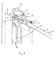
- the door handle 4 is moved from the position N Fig. 7 in the position E according to Fig. 8 manually twisted. According to Fig. 8 the position E of the door handle 4 is directed vertically downwards.
- door latch 5 is also rotated, so that its locking surface. 6 slides on the first mating surface 8 of the closing element 7 in the direction of the minimum slope value. If the minimum slope value is reached, the door handle 4 has taken its end position E and the seal 21 is compressed, which by the position S in Fig. 8 is symbolized.
- the closing element 7 is in its blocking position SP, which is also in Fig. 8 is shown.
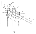
- the closing element 7 has a second lug 20 with a second mating surface 23, in this movement, the locking surface 6 engages with this second mating surface 23 so that the door is stopped again after a predetermined opening stroke of, for example, about 10 mm.
- the door handle 4 rotates from the vertical downward position in the horizontal position. In this ventilation position, in turn, a venting of the space of the device G is possible.
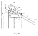
- Fig. 10 illustrates the state in which the door handle 4 beyond its horizontal position, for example, by about 5 or 10 degrees further to fully open the door 2.
- the door handle 4 from the in Fig. 8 shown rotated vertically downward position in the horizontal position. In this position, however, the door is still held by the interaction between the door latch 5 and closing element 7. Only when the door handle 4, as in Fig. 10 shown, for example, by another 10 or 15 degrees is turned up, the closing element 7 and the door latch 5 no longer overlap, so that the door 2 can be fully opened.
- the door handle 4 works against a spring force, which otherwise in his in Fig. 7 neutral position N is maintained.
Landscapes
- Engineering & Computer Science (AREA)
- Chemical & Material Sciences (AREA)
- Combustion & Propulsion (AREA)
- Mechanical Engineering (AREA)
- General Engineering & Computer Science (AREA)
- Specific Sealing Or Ventilating Devices For Doors And Windows (AREA)
- Power-Operated Mechanisms For Wings (AREA)
- Washing And Drying Of Tableware (AREA)
- Cookers (AREA)
Claims (11)
- Dispositif de fermeture (1) pour la porte (2) d'appareils de cuisine industrielle (G), en particulier d'appareils de cuisson tels que des cuiseurs vapeurs à air chaud ou étuves à circulation d'air chaud,- avec une poignée de porte (4) pouvant être disposée sur le côté visible d'un vantail (3) de la porte (2) ;- avec un verrou de porte (5) qui est relié à la poignée de porte (4) et présente une surface de verrou (6) ; et- avec un élément de fermeture (7) côté appareil à l'état monté du dispositif de fermeture (1) qui présente une première surface antagoniste (8) qui coopère au moins dans la position de fermeture (S) de la porte (2) avec la surface de verrou (6) du verrou de porte (5), rendant étanche l'appareil (G)
caractérisé en ce que- le verrou de porte (5) est relié de manière bloquée en rotation à la poignée de porte (4) ;- la surface de verrou (6) présente une inclinaison avec une valeur d'inclinaison maximale et une valeur d'inclinaison minimale qui est active à l'état monté du dispositif de fermeture (1), par rotation de la poignée de porte (4) dans une position finale de poignée de porte (E) définie par rapport à la surface antagoniste (8) pour atteindre la position de fermeture (S) de la porte (2),- l'élément de fermeture (7) est logé de manière mobile en rotation et- l'élément de fermeture (7) est précontraint, à l'état monté du dispositif de fermeture (1), de manière flexible élastiquement transversalement au sens de fermeture de la porte (2) dans la position de fermeture (S). - Dispositif de fermeture selon la revendication 1, caractérisé en ce que la surface de verrou (6) du verrou de la porte (5) est réalisée comme une surface hélicoïdale (SF).
- Dispositif de fermeture selon la revendication 1 ou 2, caractérisé en ce que le verrou de la porte (5) présente un contact (9) qui est disposé de manière bloquée en rotation sur un embout d'arbre (10) de la poignée de porte (4).
- Dispositif de fermeture selon la revendication 3, caractérisé en ce que le verrou de porte (5) est logé de manière axialement réglable sur l'embout d'arbre (10).
- Dispositif de fermeture selon l'une quelconque des revendications 1 à 4, caractérisé en ce que la surface de verrou (6) est courbée de manière concave.
- Dispositif de fermeture selon l'une quelconque des revendications 1 à 5, caractérisé en ce que l'élément de fermeture (7) est réalisé comme un loqueteau rotatif qui est logé de manière rotative autour d'un axe (A) au moins approximativement vertical.
- Dispositif de fermeture selon la revendication 6, caractérisé en ce que l'élément de fermeture (7) est précontraint dans sa position de blocage (SP) à l'aide d'un élément de ressort (11).
- Dispositif de fermeture selon l'une quelconque des revendications 1 à 7, caractérisé en ce que l'élément de fermeture (7) présente une seconde surface antagoniste (23) qui coopère, à l'état monté du dispositif de fermeture (1), avec la surface de verrou (6) dans une position de ventilation (AR) de la porte (2).
- Dispositif de fermeture selon l'une quelconque des revendications 1 à 8, caractérisé en ce que l'élément de fermeture (7) peut être logé dans un boitier (15) guidé de manière mobile longitudinalement sur l'appareil (G) et précontraint dans la position de fermeture.
- Dispositif de fermeture selon l'une quelconque des revendications 1 à 9, caractérisé par un mécanisme de commande, de préférence un entraînement par moteur électrique, pour le déplacement de l'élément de fermeture (7).
- Dispositif de fermeture selon l'une quelconque des revendications 1 à 10, caractérisé en ce que la poignée de porte (4) est précontrainte de manière commandée par ressort dans une position neutre (N).
Applications Claiming Priority (3)
| Application Number | Priority Date | Filing Date | Title |
|---|---|---|---|
| DE10309594 | 2003-03-05 | ||
| DE2003109594 DE10309594B4 (de) | 2003-03-05 | 2003-03-05 | Verschlusseinrichtung für die Tür von Großküchengeräten |
| PCT/EP2004/002259 WO2004081324A1 (fr) | 2003-03-05 | 2004-03-05 | Dispositif de fermeture pour portes d'appareils de cuisines industrielles |
Publications (2)
| Publication Number | Publication Date |
|---|---|
| EP1599650A1 EP1599650A1 (fr) | 2005-11-30 |
| EP1599650B1 true EP1599650B1 (fr) | 2010-05-19 |
Family
ID=32891880
Family Applications (1)
| Application Number | Title | Priority Date | Filing Date |
|---|---|---|---|
| EP04717594A Expired - Lifetime EP1599650B1 (fr) | 2003-03-05 | 2004-03-05 | Dispositif de fermeture pour portes d'appareils de cuisines industrielles |
Country Status (3)
| Country | Link |
|---|---|
| EP (1) | EP1599650B1 (fr) |
| DE (1) | DE10309594B4 (fr) |
| WO (1) | WO2004081324A1 (fr) |
Families Citing this family (8)
| Publication number | Priority date | Publication date | Assignee | Title |
|---|---|---|---|---|
| US7089948B2 (en) * | 2002-05-03 | 2006-08-15 | Whirlpool Corporation | In-sink dishwasher with integrated latch |
| DE102006013519A1 (de) * | 2006-03-23 | 2007-10-11 | BSH Bosch und Siemens Hausgeräte GmbH | Vorrichtung mit einer Gargerätetür, einer Aktoreinheit und einem Verriegelungselement |
| DE102007016130A1 (de) * | 2007-03-29 | 2008-10-02 | Robert Bosch Gmbh | Fixiereinrichtung sowie Messvorrichtung |
| DE102008024341B4 (de) * | 2008-05-20 | 2020-12-31 | Volkswagen Ag | Türbetätigungsvorrichtung mit einer Notöffnungseinrichtung |
| ITTV20130169A1 (it) * | 2013-10-17 | 2015-04-18 | Lainox Ali Spa | "apparecchiatura per la cottura di alimenti nella ristorazione collettiva con dispositivo di apertura automatica della porta" |
| CN104545753B (zh) * | 2014-12-31 | 2017-01-25 | 宁波方太厨具有限公司 | 用于清洗机的电磁锁 |
| CN111846801A (zh) * | 2020-06-19 | 2020-10-30 | 东风柳州汽车有限公司 | 转动式吊挂装置 |
| CN112956902B (zh) * | 2021-03-19 | 2021-12-21 | 北京市泰坦不锈钢厨具有限责任公司 | 一种燃气蒸柜 |
Family Cites Families (5)
| Publication number | Priority date | Publication date | Assignee | Title |
|---|---|---|---|---|
| US2741505A (en) * | 1954-06-07 | 1956-04-10 | Gen Motors Corp | Door fastener |
| US2784023A (en) * | 1955-12-27 | 1957-03-05 | Pisani Joseph | Lock releasing device in refrigerators |
| JPS5537088A (en) * | 1978-09-07 | 1980-03-14 | Sanyo Electric Co Ltd | Projection-type color television device |
| EP1111175B1 (fr) * | 1999-12-24 | 2004-03-03 | Rahrbach GmbH | Serrure de portes d'appareils |
| DE10143640C5 (de) * | 2001-09-06 | 2007-02-08 | Rational Ag | Sicherheitsvorrichtung für begehbare Innenräume, insbesondere von Gargeräten |
-
2003
- 2003-03-05 DE DE2003109594 patent/DE10309594B4/de not_active Expired - Fee Related
-
2004
- 2004-03-05 WO PCT/EP2004/002259 patent/WO2004081324A1/fr not_active Ceased
- 2004-03-05 EP EP04717594A patent/EP1599650B1/fr not_active Expired - Lifetime
Also Published As
| Publication number | Publication date |
|---|---|
| DE10309594B4 (de) | 2006-04-20 |
| EP1599650A1 (fr) | 2005-11-30 |
| DE10309594A1 (de) | 2004-09-23 |
| WO2004081324A1 (fr) | 2004-09-23 |
Similar Documents
| Publication | Publication Date | Title |
|---|---|---|
| EP0261267B1 (fr) | Fermeture de barre pour portes d'armoires en tôle | |
| EP1617023B1 (fr) | Serrure pour ouvrants ou portes d'un véhicule | |
| DE3135401A1 (de) | Tor mit einer verriegelungseinrichtung | |
| EP1599650B1 (fr) | Dispositif de fermeture pour portes d'appareils de cuisines industrielles | |
| DE102011084571B4 (de) | Vorrichtung zur Behandlung von Lebensmitteln mit verbesserter Tür-Anbindung | |
| EP1893834A1 (fr) | Dispositif d'ouverture de porte electrique pour portes en verre | |
| DE4208216A1 (de) | Tuerverschluss fuer geraete | |
| DE102010032742B3 (de) | Verschluss für eine Gerätetür | |
| EP2947221B1 (fr) | Fenêtre de toit et procédé de montage d'une fenêtre de toit | |
| DE3912483C2 (fr) | ||
| DE3404220C2 (de) | Versenkbar angeordneter Türgriff, insbesondere für Backofentüren von Herden | |
| EP3273164B1 (fr) | Appareil de cuisson comprenant un dispositif de verrouillage | |
| DE19902579C2 (de) | Verschlußvorrichtung für den unterschlagenden Flügel zweiflügeliger setzholzloser Fenster oder Türen | |
| EP3702566A1 (fr) | Fermeture à charnière | |
| EP1532913B1 (fr) | Dispositif d'amortissement de sièges de toilettes et/ou de couvercle de toilettes | |
| DE19724318A1 (de) | Verschluß für Türen, Hauben, Klappen o. dgl., insbesondere von Fahrzeugen, wie Kraftfahrzeugen | |
| EP2732113B1 (fr) | Fermoir permettant de fermer une porte, plus particulièrement une porte d'appareil | |
| EP2558668A1 (fr) | Dispositif de guidage de déplacement d'une porte d'appareil ménager, porte d'appareil ménager, appareil ménager muni d'une porte et procédé d'actionnement d'une porte d'appareil ménager | |
| DE60017340T2 (de) | Schnellsperrvorrichtung, insbesondere für die Tür eines Mikrowellenofens | |
| DE4443098A1 (de) | Haushaltgerät mit einer schwenkbar gelagerten Gerätetür | |
| DE9314325U1 (de) | Flügelscharnier | |
| EP2944746B1 (fr) | Dispositif de fermeture | |
| DE2020240B2 (de) | Verschluss fuer einen schwenk-kippfluegel eines fensters, einer tuer o.dgl. | |
| WO2017190723A1 (fr) | Entraînement de porte pour portes à deux battants | |
| DE202016102402U1 (de) | Türantrieb für Doppeltüren |
Legal Events
| Date | Code | Title | Description |
|---|---|---|---|
| PUAI | Public reference made under article 153(3) epc to a published international application that has entered the european phase |
Free format text: ORIGINAL CODE: 0009012 |
|
| 17P | Request for examination filed |
Effective date: 20050803 |
|
| AK | Designated contracting states |
Kind code of ref document: A1 Designated state(s): AT BE BG CH CY CZ DE DK EE ES FI FR GB GR HU IE IT LI LU MC NL PL PT RO SE SI SK TR |
|
| AX | Request for extension of the european patent |
Extension state: AL LT LV MK |
|
| DAX | Request for extension of the european patent (deleted) | ||
| RBV | Designated contracting states (corrected) |
Designated state(s): ES FR GB IT NL |
|
| REG | Reference to a national code |
Ref country code: DE Ref legal event code: 8566 |
|
| 17Q | First examination report despatched |
Effective date: 20070615 |
|
| GRAP | Despatch of communication of intention to grant a patent |
Free format text: ORIGINAL CODE: EPIDOSNIGR1 |
|
| GRAS | Grant fee paid |
Free format text: ORIGINAL CODE: EPIDOSNIGR3 |
|
| GRAA | (expected) grant |
Free format text: ORIGINAL CODE: 0009210 |
|
| AK | Designated contracting states |
Kind code of ref document: B1 Designated state(s): ES FR GB IT NL |
|
| REG | Reference to a national code |
Ref country code: GB Ref legal event code: FG4D Free format text: NOT ENGLISH |
|
| REG | Reference to a national code |
Ref country code: NL Ref legal event code: VDEP Effective date: 20100519 |
|
| PG25 | Lapsed in a contracting state [announced via postgrant information from national office to epo] |
Ref country code: ES Free format text: LAPSE BECAUSE OF FAILURE TO SUBMIT A TRANSLATION OF THE DESCRIPTION OR TO PAY THE FEE WITHIN THE PRESCRIBED TIME-LIMIT Effective date: 20100830 |
|
| PG25 | Lapsed in a contracting state [announced via postgrant information from national office to epo] |
Ref country code: NL Free format text: LAPSE BECAUSE OF FAILURE TO SUBMIT A TRANSLATION OF THE DESCRIPTION OR TO PAY THE FEE WITHIN THE PRESCRIBED TIME-LIMIT Effective date: 20100519 |
|
| PLBE | No opposition filed within time limit |
Free format text: ORIGINAL CODE: 0009261 |
|
| STAA | Information on the status of an ep patent application or granted ep patent |
Free format text: STATUS: NO OPPOSITION FILED WITHIN TIME LIMIT |
|
| 26N | No opposition filed |
Effective date: 20110222 |
|
| GBPC | Gb: european patent ceased through non-payment of renewal fee |
Effective date: 20110305 |
|
| REG | Reference to a national code |
Ref country code: FR Ref legal event code: ST Effective date: 20111130 |
|
| PG25 | Lapsed in a contracting state [announced via postgrant information from national office to epo] |
Ref country code: FR Free format text: LAPSE BECAUSE OF NON-PAYMENT OF DUE FEES Effective date: 20110331 |
|
| PG25 | Lapsed in a contracting state [announced via postgrant information from national office to epo] |
Ref country code: GB Free format text: LAPSE BECAUSE OF NON-PAYMENT OF DUE FEES Effective date: 20110305 |
|
| PGFP | Annual fee paid to national office [announced via postgrant information from national office to epo] |
Ref country code: IT Payment date: 20190322 Year of fee payment: 16 |
|
| PG25 | Lapsed in a contracting state [announced via postgrant information from national office to epo] |
Ref country code: IT Free format text: LAPSE BECAUSE OF NON-PAYMENT OF DUE FEES Effective date: 20200305 |