EP1600007B1 - Dispositif de representation spatiale - Google Patents
Dispositif de representation spatiale Download PDFInfo
- Publication number
- EP1600007B1 EP1600007B1 EP04714289A EP04714289A EP1600007B1 EP 1600007 B1 EP1600007 B1 EP 1600007B1 EP 04714289 A EP04714289 A EP 04714289A EP 04714289 A EP04714289 A EP 04714289A EP 1600007 B1 EP1600007 B1 EP 1600007B1
- Authority
- EP
- European Patent Office
- Prior art keywords
- filter
- image
- array
- elements
- arrangement according
- Prior art date
- Legal status (The legal status is an assumption and is not a legal conclusion. Google has not performed a legal analysis and makes no representation as to the accuracy of the status listed.)
- Revoked
Links
- 238000003491 array Methods 0.000 claims abstract description 14
- 238000001429 visible spectrum Methods 0.000 claims description 24
- 230000005540 biological transmission Effects 0.000 claims description 5
- 239000011159 matrix material Substances 0.000 claims description 4
- 230000000694 effects Effects 0.000 claims description 3
- 238000005286 illumination Methods 0.000 claims description 3
- 210000001747 pupil Anatomy 0.000 claims description 2
- 230000003068 static effect Effects 0.000 claims description 2
- 239000004973 liquid crystal related substance Substances 0.000 claims 2
- 230000000873 masking effect Effects 0.000 claims 2
- 238000013507 mapping Methods 0.000 claims 1
- 239000011521 glass Substances 0.000 abstract description 2
- 230000006870 function Effects 0.000 description 6
- 238000000034 method Methods 0.000 description 6
- 239000000203 mixture Substances 0.000 description 4
- 230000000737 periodic effect Effects 0.000 description 3
- 238000002834 transmittance Methods 0.000 description 2
- 239000002131 composite material Substances 0.000 description 1
- 230000003247 decreasing effect Effects 0.000 description 1
- 230000001419 dependent effect Effects 0.000 description 1
- 230000001771 impaired effect Effects 0.000 description 1
- 230000007935 neutral effect Effects 0.000 description 1
- 230000008447 perception Effects 0.000 description 1
- 238000001228 spectrum Methods 0.000 description 1
- 230000007704 transition Effects 0.000 description 1
- 230000000007 visual effect Effects 0.000 description 1
Images



















Classifications
-
- H—ELECTRICITY
- H04—ELECTRIC COMMUNICATION TECHNIQUE
- H04N—PICTORIAL COMMUNICATION, e.g. TELEVISION
- H04N13/00—Stereoscopic video systems; Multi-view video systems; Details thereof
- H04N13/30—Image reproducers
- H04N13/356—Image reproducers having separate monoscopic and stereoscopic modes
- H04N13/359—Switching between monoscopic and stereoscopic modes
-
- H—ELECTRICITY
- H04—ELECTRIC COMMUNICATION TECHNIQUE
- H04N—PICTORIAL COMMUNICATION, e.g. TELEVISION
- H04N13/00—Stereoscopic video systems; Multi-view video systems; Details thereof
-
- H—ELECTRICITY
- H04—ELECTRIC COMMUNICATION TECHNIQUE
- H04N—PICTORIAL COMMUNICATION, e.g. TELEVISION
- H04N13/00—Stereoscopic video systems; Multi-view video systems; Details thereof
- H04N13/30—Image reproducers
- H04N13/302—Image reproducers for viewing without the aid of special glasses, i.e. using autostereoscopic displays
- H04N13/31—Image reproducers for viewing without the aid of special glasses, i.e. using autostereoscopic displays using parallax barriers
Definitions
- the invention relates to arrangements for spatial representation, in particular to those that offer one or more viewers without additional aids such as glasses a three-dimensionally perceptible image.
- At least one wavelength filter array is used which predefines propagation directions for light of different picture elements.
- Said picture elements provide picture part information of several views of a scene Due to the given direction of light propagation, the eyes of a viewer will see predominantly a first and a second selection of views, thereby creating a spatial impression in the viewer.
- DE20121318 U1 discloses an arrangement for the spatial representation of a scene or an object according to the preamble of claim 1.
- n, n ⁇ 3 of the scene / object, one or more arrays of a plurality of individual arranged in rows q and columns p, as filter elements ⁇ pq executed wavelength and / or grayscale filter of which a part is translucent in predetermined wavelength ranges, and the remaining part is opaque and which are forward and / or downstream of the imager with the picture elements ⁇ ij in the viewing direction, so that propagation directions are predetermined for the light emitted by the picture elements ⁇ ij wherein in each case a picture element ⁇ ij with a plurality of associated filter elements or a filter element with corresponds to a plurality of associated pixels ⁇ ij such that in each case the connecting line between the center of a visible portion of the pixel ⁇ ij and the center of area of a visible portion of the filter element corresponds to a propagation direction, wherein the propagation directions within a viewing space in which the / stay the viewer , in a plurality of points of intersection, each corresponding to a viewing
- n optically perceives, solved in that on at least one of the arrays, the ratio of the surface areas of the for the entire visible spectrum translucent filter elements ⁇ pq to the total area of all filter elements ⁇ pq multiplied by the average number n 'of the various views represented per row j of the raster of pixels ⁇ ij is greater than 1 and at most 2.
- the brightness can be increased.
- the detail corresponds to at least one row j or at least one column i in parallel projection onto the grid of pixels ⁇ ij .
- the 3D impression is not noticeably impaired, with parallel projection of a sufficiently large filter section at least one provided array of filter elements ⁇ pq on at least one row j or at least one column i of the grid at least 1.1 / n'-times and at most, however, the 1.8 / n'-times the area of the corresponding line j or column i covered by the entire visible spectrum substantially translucent filter elements ⁇ pq , so that due to the entire visible spectrum light transmissive filter elements ⁇ pq on average per visible grid section with respect to the pixel surface is always about 1.1 to 1.8 pixels ⁇ ij visible.
- At least one first belt of transparent filters extending from one edge of the array to an opposite edge and continuously passing through is provided, and at least one second belt of transparent filters extending from one edge of the array to an opposite edge and continuously passing through the main propagation directions of these two belts on the array are non-parallel to each other.
- main propagation direction in this context is meant the connecting line between two transparent filters of one and the same belt, which are respectively positioned at opposite ends of the belts.
- centroid of the total area of the corresponding transparent filters is meant.
- At least one of the provided continuous belts of transparent filters runs parallel to the upper, lower, left or right edge of the respective array of filter elements ⁇ pq and / or parallel to the upper, lower, left or right edge of the raster of picture elements ⁇ ij .
- a plurality of such continuous belt is provided by transparent filters.
- At least a portion of the continuous belts of transparent filters are randomly distributed over the array insofar as said belts are parallel to each other.
- at least a portion of the continuous belt of transparent filters at periodic intervals to each other on the array is arranged, as far as said belt are parallel to each other, wherein preferably each m.
- Column p (with m> 1) of the corresponding array forms such a continuous belt of transparent filters.
- a plurality of such picture elements ⁇ ij to be at least partially covered by transparent filters, which reproduce the partial information of at least two different views A k .
- i denotes the index of a picture element ⁇ ij in a row of the screen
- j the index of a picture element ⁇ ij in a column of the screen
- the function IntegerPart returns as its value the largest integer that does not exceed the argument in brackets in the equation.
- b is an integer which defines, for a filter element ⁇ pq at position (p, q), one of the provided transparency wavelengths / wavelength ranges or transmittances ⁇ b and may have values between 1 and b max , where b max is a natural number greater than 1.
- n m is an integer value greater than "zero", which preferably corresponds to the total number k of views A k represented in the combination image, and d pq is a selectable mask coefficient matrix for varying the generation of a mask image.
- IntegerPart has already been defined above.
- s p denotes the average horizontal distance between two adjacent picture elements ⁇ ij . If the filter array lies in the viewing or normal direction in front of the grid of pixels ⁇ ij , then z is subtracted from d a ; if the filter array is behind, then z is added to d a .
- p d is the mean pupil distance in a viewer and d a is a selectable viewing distance.
- Typical distances z are approximately in the range of 1 mm to 25 mm; however, other, in particular larger distances are also conceivable.
- all filter elements provided on the filter array (s) are the same size.
- the surface area of a filter or a filter element can in this context generally have an area of a few thousand square microns to a few square millimeters.
- the filter elements or filters ⁇ pq have polygonal, preferably rectangular outlines. Further, the outlines may also include curved lines.
- the picture elements ⁇ ij other shapes, such as polygonal shapes or stripes in the manner of a herringbone pattern as in a so-called dual-domain display, conceivable.
- the filter elements ⁇ pq provided on the filter array (s) preferably each have an essentially periodic arrangement.
- the light propagation directions for the partial information reproduced on the picture elements ⁇ ij are predetermined as a function of their wavelength / their wavelength range.
- a further embodiment provides that adjacent to at least one of the provided arrays of filter elements in at least one line q of the array immediately adjacent transparent filter to another number immediately adjacent positioned transparent filter on the line q-1, as on the line q + 1. In this way, the views transitions are influenced by a viewer movement.
- each of the provided filter arrays is designed as a static, temporally invariable filter array and arranged substantially in a fixed relative position to the grid of picture elements ⁇ ij , ie the imager.
- At least one picture element ⁇ ij outputs one partial information at least two different views A k mixed image information again, for example by means of one of in the WO 03/024112 the Applicant described method.
- the imager can be, for example, an LC display, a plasma display or an OLED screen.
- the imager can also be different types of devices.
- a switchable diffuser between the image display device and the filter array is provided so that in a first mode in which the switchable diffuser is switched transparent, for the / the viewer a spatial impression is generated, while in a second mode in which the switchable Lens is switched at least partially scattering, the effect of the array of filter elements is largely eliminated, so that the scattered light allows a largely homogeneous illumination of the image display device and can be displayed perceptible on this two-dimensional image content in full resolution.
- said second mode accordingly, no light propagation directions are predetermined at the corresponding subareas on which the diffuser is switched, so that both eyes of the respective observer see substantially the same image part information.
- at the corresponding 2D locations on the imager only two-dimensional image information, i. no image composed of multiple views.
- At least one array of filter elements can be provided for 2D-3D switching, which at least partially as a wavelength or grayscale filter pixels having an electrochromic or photochromic structure includes, the array in a first mode for the 3D representation in particular under Using the electrochromic or photochromic constructed pixels exhibited suitable for spatial representation Filterarray Vietnamese while in a second mode, the electrochromic or photochromic pixels as transparent as possible, preferably for the complete visible spectrum substantially completely transparent, are switched.
- both electrochromic or photochromic constructed as well as immutable in their transmission characteristics wavelength or gray level filter can be provided, the invariable filter are preferably formed for the complete visible spectrum substantially completely transparent.
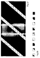
- FIG. 1a represents-as a section-a filter array in a first embodiment of the arrangement according to the invention.
- the filter array is constructed from a multiplicity of wavelength filters.
- substantially transparent and opaque filters or filter elements are provided only for the visible spectrum.
- the transparent filter sections of the filter array known from FIG. 1 a are composed of a plurality of transparent filter elements.
- the dimensions of the (smallest) transparent filter elements here are approximately 0.0997151 mm wide and 0.2991453 mm high in Fig.1b, in that the pixel grid is a 15.1 "LG type LC display with a resolution of 1024x768 pixels at 0.3
- the dimensions of the composite transparent filter sections shown in Figure 1a are thus inherently given
- the filter array has approximately the same areal extent as the active image area of an LC display or in general of the imager.
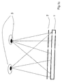
- FIG. 1 c in which schematically indicated observer eyes 3 look at a filter array 2.
- the translucent in predetermined wavelength ranges filter elements are designed as a transparent filter.
- n' 4 in this case.
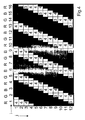
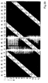
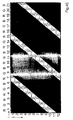
- FIGS. 3 and 4 show examples of possible picture elements or picture element sub-areas which are visible for the two observer's eyes, on the basis of the conditions according to FIGS. 1 a and 2. From these it can be seen that, due to the filter elements ⁇ pq transmitting the complete visible spectrum, ie the transparent filter, on average about 1.1 to 1.8 picture elements ⁇ ij are always visible per visible screen segment with respect to the picture element area say about 1.33 pixels ⁇ ij . For example, at the point (1,1) in FIG. 3, about 0,33 visible picture elements (with respect to the picture element area) of the picture element on the right adjoin the left upper visible picture element.
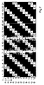
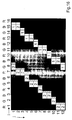
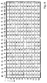
- FIG. 5 shows another example of the image combination, particularly suitable for a mobile display, such as a PDA (Personal Digital Assistant) or a mobile phone.
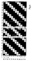
- FIG. 6 shows a filter array which is very well suited for the spatial representation in conjunction with the image combination specification according to FIG. 5, with which a configuration can be realized in which at parallel projection of a sufficiently large filter section at least one provided array of filter elements .beta.
- filter elements ⁇ pq Pq on at least one row j or on at least one column i of the grid at least 1.1 / n 'times and at most the 1.8 / n' times the area of the corresponding row j or column i of the complete visible spectrum substantially translucent filter elements ⁇ pq is covered, so that due to the for the complete visible spectrum light-transmitting filter elements ⁇ pq on average per visible grid section with respect to the pixel surface always about 1.1 to 1.8 pixels ⁇ ij are visible.
- the translucent in predetermined areas filter elements are also designed as a transparent filter.
- RGB Farbsubpixelzeilen As a special feature in the image combination according to Figure 5, it should be noted that these are RGB Farbsubpixelzeilen and not as many LCD screens are RGB Farbsubpixelspalten.
- Such a picture structure is present, for example, in a PDA (Personal Digital Assistant) of the type Compaq iPAQ 3600 Pocket PC; said PDA type is therefore ideal for the 3D representation in connection with the previously described applications.
- the filter dimensions are here - according to the dashed in Figure 6 rectangle - for example, 0.319607 mm width and 0.079922 mm height.
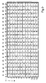
- FIG. 9 shows a further example of the image combination
- FIG. 10 shows a filter array which is very well suited for the spatial representation in conjunction with the image combination rule according to FIG.
- a grid of pixels ⁇ ij here comes, for example, a plasma display of the type Pioneer PDP 503 MXE in question.
- the filter dimensions are here - corresponding to the dashed in Fig.10 rectangle - for example, 0.377964 mm width and 0.80442478 height.
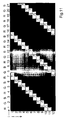
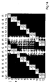
- FIGS. 11 and 12 show examples of possible picture elements or picture element sub-areas that are visible for the two observers' eyes on the basis of the relationships according to FIGS. 9 and 10.
- FIG. 13a shows the schematic composition of transparent filter sections made up of a plurality of transparent filters or filter elements.
- the filter array in Fig. 13b is equivalent to the filter array of Fig. 13a.
- FIG. 14 shows an example of the picture elements or picture element sub-areas that are visible to a viewer's eye on the basis of the relationships according to FIG. 9 and FIG.
- the filter array according to FIG. 13a or FIG. 13b the case is realized that on at least one of the provided arrays of filter elements in at least one line q of the array immediately adjacent transparent filters to another number immediately adjacent positioned transparent filter on the line q -1, than on the line q + 1.
- a filter array according to the invention in Fig.15 is shown. This filter array is likewise preferably to be used with an image combination rule according to FIG.
- FIG. 16 shows an example of the picture elements or picture element sub-areas which are visible to a viewer's eye on the basis of the conditions according to FIG. 9 and FIG.
- the case is also realized that on at least one of the provided arrays of wavelength or grayscale filters in at least one line q of the array immediately adjacent transparent filters to another number immediately adjacent positioned transparent filter on the line q -1, than on the line q + 1.
- FIG. 17 shows a filter array in a further embodiment of the invention, preferably to be used with an image combination rule according to FIG. 9, while FIG. 18 shows an example of possible image elements or image element subareas visible to a viewer eye on the basis of the conditions according to Fig.9 and Fig.17 reproduces.
- FIG. 19 shows a further example of the image combination and in FIG. 20 a filter array according to the present invention which is very well suited for the spatial representation in conjunction with the image combination rule according to FIG.
- FIGS. 21 and 22 show examples of possible picture elements or picture element sub-areas that are visible for the two observers, on the basis of the relationships according to FIGS. 19 and 20.
- eight views for presentation which are also shown in each row.
- e.g. 40 views are also shown, wherein preferably only eight different views are used per line (for example, 1, 6, 11, 16, 21, 26, 31, 36).
- FIG. 23 shows the further example of the image combination
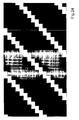
- FIG. 24 shows a filter array very well suited for the spatial representation in conjunction with the image combination rule according to FIG. 23
- FIGS. 25 and 26 provide examples of possible image elements visible to the two observer eyes or picture element sub-areas on the basis of the conditions according to FIGS. 23 and 24. Again, eight views are used for the spatial representation.
- a third variant of the arrangements according to the invention in which at least one first belt of transparent filters extending from one edge of the array to an opposite edge and continuously passing through is provided and at least one second belt of transparent filters extending from one edge of the array to an opposite edge and continuously passing through With the main propagation directions of these two belts on the array aligned non-parallel to each other, will be discussed in detail in the further drawings.
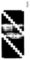
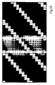
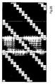
- FIG. 27 shows a further example of the image combination and FIG. 28 a matching filter array with horizontal transparent filter belts according to this embodiment of the arrangement according to the invention.
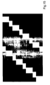
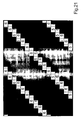
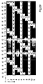
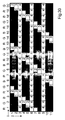
- Figs. 29 and 30 show Examples of possible visible for the two observers picture elements or picture element sub-areas on the basis of the ratios according to Fig.27 and Fig.28.
- horizontal belts of transparent filters are provided by way of example here.
- other (stepped, oblique) belts are provided respectively from the lower to the upper edge of the filter array, so that the main propagation directions of the horizontal and oblique belts are non-parallel to each other.
- the filter array contains many more filter elements; For the sake of clarity, only one part of the filter array - cut out arbitrarily - is shown here.
- a plurality of such continuous belts of transparent filters is advantageously provided.
- advantageously some or all of the continuous horizontal belts of transparent filters are arranged on the array at periodic intervals.
- FIG. 31 shows the corresponding example of the image combination
- FIG. 32 shows a filter array which is very well suited for this purpose, inter alia vertical transparent filter belts
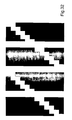
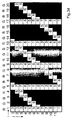
- FIGS. 33 and 34 show examples of possible image elements or picture element subareas visible to the two observer eyes.
- FIG. 32 an oblique, on the other hand, vertical continuous belt of transparent filters are provided here.
- Fig. 34 would correspond approximately to a slightly offset oblique view and not parallel projection in the viewing direction (which, strictly speaking, would lie parallel to the perpendicular bisector on the pixel grid), but rather parallel projection in an oblique direction.
- the image combination rule in such a way that parallel projection of at least partially covers such a continuous belt of transparent filters in the viewing direction onto the grid of picture elements ⁇ ij are the partial information of at least two different views A k play .
- Different variations of the corresponding at least two views A k are conceivable: For example, more than the required two views can also be used, for example n or n-1 views.
- the image combination structure for the image elements at least partially overlapped in the case of parallel projection of transparent filters as described above can also be a random structure-and not a picture structure of partial views-as was previously presented in FIG. Decisive for the achievement of a 3D impression is that the respective observer sees with his eyes in each case different selections from views, ie mixed views.
- the width of the transparent filter belts may vary. Particularly in the case of the "oblique" belts described in more detail above, the width of the transparent filter sections per line can also be selected such that the quotient of the total area of the transparent filters on the array and the total area of all filter elements on the array is less than 1.1 / n '. or more than 1.8 / n '.
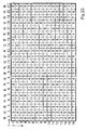
- Fig. 35 shows another filter array which can meet the requirements of the initially described embodiments of the invention, supplemented by R ', G', B 'filters and supplemented by gray scale filters.
- R 'here red, with G' green and with B 'blue wavelength filters.
- the respective filter elements cover only the outlined area proportions.
- L2 is meant grayscale filters, which are designed as neutral filters for 50 percent wavelength-independent attenuation of the light intensity.
- the R'-, G'-, B'-filters are translucent only in the respective red, green or blue wavelength range and the L2 filters attenuate the light intensity not insignificantly, so that again not from “largely permeable” or " essentially "can be spoken.
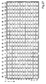
- FIG. 37 shows, as a lattice structure, the array on which the filter elements ⁇ pq are arranged.
- the individual filter elements used are shown side by side in FIG.
- FIGS. 39 and 40 show examples of the left and right viewer eyes 3, respectively, ie which picture elements with which views they see from a predetermined position of the observer. Moreover, it is also possible to arrange the strips not obliquely, but vertically. Also in this and the following example, the quotient of the sum of the surface portions of filter elements ⁇ pq , which are largely permeable to light of the substantially entire visible spectrum, and the sum of the surface portions of all filter elements ⁇ pq between 1.1 and 1.8 ,
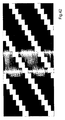
- FIGS. 41-44 A concluding example based on the aforementioned embodiments is described in FIGS. 41-44.
- 42 shows a filter array which is very well suited for the spatial representation in conjunction with the image combination specification according to FIG. 41;
- FIGS. 43 and 44 show, by way of example, which image elements with which views with the left and right viewer eyes 3 from a predetermined position see from the viewer.
- Fig. 42 the dimensions of a transparent filter are shown in dashed lines. Its width corresponds approximately to that of a picture element ⁇ ij and is for example 99.86% thereof. It is also about 1.5 times as high; for example, the height is 149.8% of the height of a pixel ⁇ ij . These ratios occur, for example, in some 18.1-inch LC displays: There, the average width of the pixels is 0.28047 mm and the average height 0.09349 mm. A transparent filter element is then about 0.420146 mm high and 0.093366 mm wide.
- the invention offers the advantage over the prior art of increasing the image brightness in the 3D display. Along with this, improved text readability is ensured on the arrangements according to the invention.
Landscapes
- Engineering & Computer Science (AREA)
- Multimedia (AREA)
- Signal Processing (AREA)
- Testing, Inspecting, Measuring Of Stereoscopic Televisions And Televisions (AREA)
- Image Processing (AREA)
- Control Of Indicators Other Than Cathode Ray Tubes (AREA)
- Eye Examination Apparatus (AREA)
- Electrochromic Elements, Electrophoresis, Or Variable Reflection Or Absorption Elements (AREA)
- Ultra Sonic Daignosis Equipment (AREA)
Claims (23)
- Dispositif de représentation spatiale d'une scène ou d'un objet, comprenant- un générateur d'image avec une pluralité d'éléments d'image respectifs (αij) dans une matrice de lignes (j) et colonnes (i), les éléments d'image (αij) représentant des informations partielles d'au moins trois vues (Ak) (k=1...n, n>=3) de la scène/de l'objet,- un ou plusieurs ensembles d'une pluralité d'éléments filtrants (βpq) respectifs, utilisés en tant que filtres de longueurs d'onde et/ou de niveau de gris, agencés en lignes (q) et colonnes (p), dont une partie est réalisée en tant que filtre transparent laissant passer la lumière de l'ensemble du spectre visible, et la partie restante est opaque, et les éléments filtrants se trouvant, dans la direction de vue, en amont et/ou en aval du dispositif de transmission d'image avec les éléments d'image (αij), de sorte que des directions de propagation soient fixées pour la lumière rayonnée des éléments d'image (αij), dans lequel respectivement un élément d'image (αij) correspond à plusieurs éléments filtrants (βpq) attribués ou un élément filtrant (βpq) correspond à plusieurs éléments d'image attribués de telle façon que respectivement la droite de liaison entre le milieu de surface d'une section visible de l'élément d'image (αij) et le milieu de surface d'une section visible de l'élément filtrant (βpq) correspond à une direction de propagation, dans lequel les directions de propagation se croisent, à l'intérieur d'une zone d'observation dans laquelle le/les observateur/s se trouve/nt, en une pluralité de points d'intersection, qui correspondent respectivement à une position d'observation, un observateur discernant optiquement, à partir de chaque position d'observation, essentiellement avec un oeil des informations partielles d'une première sélection, et essentiellement avec l'autre oeil des informations partielles d'une deuxième sélection à partir des vues (Ak) (k=1...n),caractérisé en ce que
sur au moins un des ensembles, le rapport entre les parties de surface des éléments filtrants (βpq) laissant passer la lumière pour l'ensemble du spectre visible et la surface totale de tous les éléments filtrants multiplié par le nombre moyen (n') des vues représentées différentes, par ligne (j) de la matrice des éléments d'images (αij), est supérieur à 1 et au maximum 2. - Dispositif selon la revendication 1, caractérisé en ce que le quotient de la somme des parties de surface des éléments filtrants (βpq), qui sont transparents de manière plus extensive pour la lumière de sensiblement l'ensemble du spectre visible, et de la somme des parties de surface de tous les éléments filtrants (βpq) de l'ensemble respectif prend une valeur comprise entre le quotient Q1=1,1/n' et le quotient Q2=1,8/n', de sorte que, en moyenne, on voit toujours environ 1,1 à 1,8 élément d'image par section de matrice par rapport aux surfaces d'éléments d'image parce que les éléments filtrants (βpq) sont transparents pour le spectre visible complet.
- Dispositif selon la revendication 1, caractérisé en ce que pour une projection parallèle d'une section de filtre suffisamment importante d'au moins un ensemble prévu d'éléments filtrants (βpq) sur au moins une ligne (j) ou au moins une colonne (i) de la matrice, au moins la 1,1/n'-ième et au maximum cependant la 1,8/n'-ième surface de la ligne (j) correspondante respectivement la colonne (i) correspondante est recouverte par les éléments filtrants (βpq) sensiblement transparents pour le spectre visible complet, de sorte que, en moyenne, on voit toujours environ 1,1 à 1,8 éléments d'image (αij) par section de matrice visible par rapport aux surfaces d'éléments d'image parce que les éléments filtrants (βpq) sont essentiellement transparents pour le spectre visible complet.
- Dispositif selon la revendication 1, caractérisé en ce qu'il est prévu au moins une première ceinture continue de filtres transparents, allant de manière ininterrompue d'un premier coté de l'ensemble jusqu'à un deuxième coté opposé, et au moins une deuxième ceinture continue de filtres transparents allant de manière ininterrompue d'un coté de l'ensemble jusqu'à un coté opposé, les directions principales d'extension de ces deux ceintures sur l'ensemble n'étant pas arrangées de manière parallèle.
- Dispositif selon la revendication 4, caractérisé en ce qu'au moins une des ceintures continues prévues de filtres transparents s'étend de manière parallèle au coté supérieur, inférieur, gauche ou droit de l'ensemble respectif de filtres de longueur d'ondes ou de niveaux de gris et/ou parallèle au coté supérieur, inférieur, gauche ou droit de la matrice d'éléments d'images (αij).
- Dispositif selon la revendication 4 ou 5, caractérisé en ce que une pluralité de telles ceintures continues de filtres transparents est prévue.
- Dispositif selon une quelconque des revendications 4 à 6, caractérisé en ce qu'au moins une partie des ceintures continues de filtres transparents est agencée de manière aléatoire sur l'ensemble, dans la mesure où les dites ceintures sont parallèles entre elles.
- Dispositif selon une quelconque des revendications 4 à 6, caractérisé en ce qu'au moins une partie des ceintures continues de filtres transparents est agencée sur l'ensemble avec un espacement périodique entre elles, dans la mesure où les dites ceintures sont parallèles entre elles, dans lequel, de manière avantageuse, chaque mième ligne (q) (avec m>1) de l'ensemble correspondant construit une ceinture continue correspondante de filtres transparents.
- Dispositif selon l'une quelconque des revendications 4 à 8, caractérisé en ce que pour une projection parallèle d'une telle ceinture continue de filtres transparents - mais pas nécessairement de chaque ceintures - dans la direction d'observation sur la matrice d'éléments d'image (αij), surtout les éléments d'image (αij) sont recouverts au moins en partie de filtres transparents, les éléments d'image rendant une information partielle d' une seule et même vue (Ak), soit d'une partie prédominante ou exclusivement.
- Dispositif selon l'une quelconque des revendications 4 à 8, caractérisé en ce que pour une projection parallèle d'une telle ceinture continue de filtres transparents - mais pas nécessairement pour chaque ceinture - dans la direction d'observation, sur la matrice d'éléments d'image (αij), plusieurs de tels éléments d'image (αij) sont au moins en partie recouverts de filtres transparents, rendant informations partielles d'au moins deux vues différentes (Ak).
- Dispositif selon l'une quelconque des revendications précédentes, caractérisé en ce que l'agencement des informations partielles à partir des vues (Ak) (k=1...n) pour les éléments d'image (aij) en position (i, j) est mis en oeuvre selon la fonction
 (i) l'index d'un élément d'image (αij) dans une ligne de la matrice,(j) l'index d'un élément d'image (αij) dans une colonne de la matrice,(k) le numéro en cours de la vue (Ak) (k=1...n), à partir de laquelle l'information partielle est sélectionnée, qui doit être affichée sur un élément d'image choisi (aij),(n) le numéro total des vues utilisées respectives (Ak) (k=1...n),(cij) une matrice de coefficients qui peut être choisie pour une combinaison en particulier un mélange des différentes informations partielles sélectionnées à partir des vues (Ak) (k=1...n) sur la matrice etIntegerPart, une fonction pour générer le plus grand nombre entier, qui ne dépasse pas l'argument à l'intérieur des crochets.
 - Dispositif selon l'une quelconque des revendications précédentes, caractérisé en ce que pour les ensembles de filtres prévus, les éléments filtrants (βpq) sont combinés dans une image de masque, selon leur longueur d'onde de transparence / leur domaine de longueurs d'onde de transparence / leur coefficient de transmission (λb), selon la fonction suivante
 (p) l'indice d'un élément filtrant (βpq) dans une ligne de l'ensemble respectif,(q) indice d'un élément filtrant (βpq) dans une colonne de l'ensemble respectif,(b) un nombre entier, qui fixe pour un filtre de longueurs d'onde ou de niveaux de gris (βpq) à la position (p, q) un des longueurs d'onde de transparence / leurs domaines de longueurs d'onde de transparence respectivement leurs coefficients de transmission (λb) prévus, et qui peut avoir une valeur comprise entre 1 et (bmax), avec un entier naturel bmax > 1,(nm) une valeur entière supérieure à « zero », qui correspond de manière préférée au total (k) correspondant au nombre de vues (Ak) représentées dans l'image de combinaison,(dpq) une matrice de coefficients de masques qui peut être choisie pour faire varier la création d'une image de masque etIntegerPart une fonction pour générer le plus grand nombre entier, qui ne dépasse pas l'argument à l'intérieur des crochets.
 - Dispositif selon l'une des revendications précédentes, caractérisé en ce qu'exactement un ensemble d'éléments filtrants (βpq) est prévu, et la distance (z) entre le dit ensemble et la matrice d'éléments d'image (αij), mesurée dans la direction normale, est définie selon l'équation suivante :

(sp) signifie la distance horizontale moyenne entre deux éléments d'image (αij) voisins,
(pd) signifie la distance moyenne des pupilles chez un observateur, et
da signifie une distance de vue qui peut être choisie. - Dispositif selon l'une quelconque des revendications précédentes, caractérisé en ce que tous les éléments filtrants prévus sur le ou les ensembles de filtres ont la même taille.
- Dispositif selon l'une quelconque des revendications précédentes, caractérisé en ce que les éléments filtrants prévus sur le ou les ensembles de filtres sont ordonnés de manière essentiellement périodique.
- Dispositif selon l'une quelconque des revendications précédentes, caractérisé en ce que les directions de propagation de la lumière pour l'information partielle respective rendu sur les éléments d'image (αij) sont fixées en fonction de leur de leur longueur d'onde / leur domaine de longueurs d'onde.
- Dispositif selon l'une quelconque des revendications précédentes, caractérisé en ce que sur au moins un des ensembles prévus d'éléments filtrants (βpq) dans au moins une ligne (q) de l'ensemble, des filtres transparents immédiatement voisins sont voisins d'un autre nombre de filtres transparents positionnés immédiatement voisins sur la ligne (q-1) que sur la ligne (q+1).
- Dispositif selon l'une quelconque des revendications précédentes, caractérisé en ce que chacun des ensembles de filtres prévus est agencé comme un ensemble de filtres statique, qui ne varie pas avec le temps, et est arrangé dans essentiellement une position relative fixe par rapport à la matrice d'éléments d'image (αij), c'est-à-dire par rapport au générateur d'images.
- Dispositif selon l'une quelconque des revendications précédentes, caractérisé en ce qu'au moins un élément d'image (aij) rend au moins une information d'image mélangée à partir d'informations partielles d'au moins deux vues différentes (Ak).
- Dispositif selon l'une quelconque des revendications précédentes, caractérisé en ce que le générateur d'images est un écran à cristaux liquides (LC), un écran plasma, ou un écran comprenant des OLED.
- Dispositif selon l'une quelconque des revendications précédentes, dans lequel une unité de rendu d'images translucide, par exemple un écran à cristaux liquides, et également exactement un ensemble d'éléments filtrants (βpq) est prévu, étant situé dans la direction d'observation entre l'unité de rendu d'images et une unité d'illumination plane, et dans lequel un disque de dispersion commutable est en outre prévu entre l'unité de rendu d'images et l'ensemble de filtres, de sorte que dans un premier mode de fonctionnement, dans lequel le disque de dispersion commutable est commuté pour être transparent, une impression d'espace en 3D est obtenu pour le/les observateur/s, alors que dans un deuxième mode de fonctionnement, dans lequel le disque de dispersion commutable est commuté au moins en partie dispersant, l'effet de l'ensemble d'éléments filtrants (βpq) est essentiellement annulé, de sorte que la lumière dispersée rend possible une élimination essentiellement homogène de l'unité de rendu d'images et des contenus d'image bidimensionnels peuvent être représentés sur l'unité de rendu d'images, de manière perceptible, en pleine résolution.
- Dispositif selon l'une quelconque des revendications 1 à 20, dans lequel au moins un ensemble d'éléments filtrants (βpq) est prévu, l'ensemble comprenant au moins partiellement des pixels fonctionnant en tant que filtres de longueur d'ondes ou de niveaux de gris, avec un assemblage photochrome ou électrochrome, l'ensemble presentant, dans un premier mode de fonctionnement pour la représentation en trois dimensions en particulier également sous utilisation du pixel assemblé photochrome ou électrochrome, une structure d'ensemble de filtres apte pour une représentation dans l'espace, alors que, dans un deuxième mode de fonctionnement, les pixels assemblés photochrome ou électrochromes sont commutés de façon à être aussi transparents que possible, plus particulièrement essentiellement totalement transparents pour le spectre visible complet.
- Dispositif selon la revendication 22, caractérisé en ce qu'à la fois des filtres étant implémentés électrochromes respectivement photochromes et également étant des filtres de niveaux de gris ou de longueurs d'ondes ayant des propriétés de transmission statiques sont prévus, les dits filtres ayant des propriétés de transmission statiques étant de préférence agencés pour être essentiellement complètement transparents pour le spectre visible complet.
Applications Claiming Priority (3)
| Application Number | Priority Date | Filing Date | Title |
|---|---|---|---|
| DE10309194 | 2003-02-26 | ||
| DE10309194A DE10309194B4 (de) | 2003-02-26 | 2003-02-26 | Verfahren und Anordnung zur räumlichen Darstellung |
| PCT/EP2004/001833 WO2004077839A1 (fr) | 2003-02-26 | 2004-02-25 | Procede et dispositif de representation spatiale |
Publications (2)
| Publication Number | Publication Date |
|---|---|
| EP1600007A1 EP1600007A1 (fr) | 2005-11-30 |
| EP1600007B1 true EP1600007B1 (fr) | 2007-12-19 |
Family
ID=32920657
Family Applications (1)
| Application Number | Title | Priority Date | Filing Date |
|---|---|---|---|
| EP04714289A Revoked EP1600007B1 (fr) | 2003-02-26 | 2004-02-25 | Dispositif de representation spatiale |
Country Status (11)
| Country | Link |
|---|---|
| US (1) | US8169381B2 (fr) |
| EP (1) | EP1600007B1 (fr) |
| JP (1) | JP4023626B2 (fr) |
| KR (1) | KR20050086454A (fr) |
| CN (1) | CN1754392A (fr) |
| AT (1) | ATE381856T1 (fr) |
| AU (1) | AU2004214741A1 (fr) |
| CA (1) | CA2516928A1 (fr) |
| DE (2) | DE10309194B4 (fr) |
| RU (1) | RU2323542C2 (fr) |
| WO (1) | WO2004077839A1 (fr) |
Cited By (1)
| Publication number | Priority date | Publication date | Assignee | Title |
|---|---|---|---|---|
| DE102010018083A1 (de) * | 2010-04-23 | 2011-10-27 | Tridelity Ag | Gleichzeitige Wiedergabe einer Mehrzahl von Bildern mittels einer zweidimensionalen Bilddarstellungs-Matrix |
Families Citing this family (57)
| Publication number | Priority date | Publication date | Assignee | Title |
|---|---|---|---|---|
| DE10145133C1 (de) * | 2001-09-06 | 2003-04-30 | 4D Vision Gmbh | Verfahren zur räumlichen Darstellung |
| WO2004057878A2 (fr) * | 2002-12-20 | 2004-07-08 | X3D Technologies Gmbh | Ensemble pour affichage en deux ou trois dimensions |
| DE102005017313A1 (de) | 2005-04-14 | 2006-10-19 | Volkswagen Ag | Verfahren zur Darstellung von Informationen in einem Verkehrsmittel und Kombiinstrument für ein Kraftfahrzeug |
| DE102005020151A1 (de) | 2005-04-29 | 2006-11-02 | Volkswagen Ag | Verfahren zum Steuern einer Anzeigevorrichtung in einem Kraftfahrzeug und Anzeigevorrichtung |
| DE102005020152A1 (de) | 2005-04-29 | 2006-11-02 | Volkswagen Ag | Verfahren zum Steuern der Anzeige einer geografischen Karte in einem Fahrzeug und Anzeigevorrichtung hierfür |
| CN101305311B (zh) * | 2005-11-09 | 2010-12-08 | 皇家飞利浦电子股份有限公司 | 显示设备 |
| KR101210887B1 (ko) * | 2005-12-22 | 2012-12-11 | 엘지디스플레이 주식회사 | 액정표시장치 및 그 구동방법 |
| DE102006013407A1 (de) * | 2006-03-20 | 2007-09-27 | Newsight Gmbh | Anordnung zur wahlweise dreidimensional wahrnehmbaren oder zweidimensionalen Darstellung von Bildern |
| WO2007107347A1 (fr) * | 2006-03-21 | 2007-09-27 | Newsight Gmbh | Disposition pour une représentation spatialement perceptible |
| DE102006014724B4 (de) | 2006-03-30 | 2023-06-29 | Volkswagen Ag | Informationssystem für Insassen eines Kraftfahrzeugs |
| DE102006024615B4 (de) | 2006-05-26 | 2018-08-09 | Volkswagen Ag | Verfahren zur Auswahl und Anzeige einer visuellen Darstellung für eine Bedienfunktion einer Bedieneinrichtung in einem Fahrzeug und Bedieneinrichtung |
| DE102006032117A1 (de) * | 2006-07-12 | 2008-01-24 | Volkswagen Ag | Informationssystem für ein Verkehrsmittel und Verfahren zum Steuern eines solchen Informationssystems |
| JP5121198B2 (ja) * | 2006-09-22 | 2013-01-16 | 独立行政法人物質・材料研究機構 | 光透過フィルタを用いた画像出力装置及び並列アナログ演算装置 |
| DE102007016773B4 (de) * | 2007-04-04 | 2011-12-22 | Wise Vision Holdings Ltd. | Verfahren und Anordnung zur dreidimensionalen Darstellung |
| DE102007026628B3 (de) | 2007-06-07 | 2008-08-14 | Visumotion Gmbh | Verfahren zur Ausrichtung eines Parallaxenbarriereschirms auf einem Bildschirm |
| DE102007039079B4 (de) | 2007-08-16 | 2011-07-21 | VisuMotion GmbH, 07745 | Verfahren und Anordnung zur räumlichen Darstellung einer Szene mit nur geringer oder ohne Beleuchtung |
| DE102007045385B3 (de) * | 2007-09-20 | 2009-04-23 | Visumotion Gmbh | Verfahren zur Verkürzung oder Verlängerung eines Betrachtungsabstandes zwischen Betrachter und einer Anordnung zur räumlich wahrnehmbaren Darstellung |
| DE102007047470B3 (de) * | 2007-09-28 | 2009-05-28 | Visumotion Gmbh | Verfahren zur Ausrichtung eines Parallaxenbarriereschirms auf einem Bildschirm |
| DE102007054011B4 (de) * | 2007-11-09 | 2012-06-14 | Visumotion Gmbh | Verfahren und Anordnung zur räumlichen Darstellung |
| US20090128900A1 (en) * | 2007-11-15 | 2009-05-21 | Idyllic Spectrum Sdn Bhd | Autostereoscopic display |
| DE102008007727A1 (de) * | 2008-02-05 | 2009-08-13 | Visumotion Gmbh | Verfahren und Anordnung zur räumlichen Darstellung mit farblich-sequentieller Beleuchtung |
| JP2009230635A (ja) * | 2008-03-25 | 2009-10-08 | Olympus Imaging Corp | 画像データ生成装置、画像データ生成方法、および画像データ生成用プログラム |
| DE102008017051B4 (de) | 2008-04-03 | 2023-12-28 | Volkswagen Ag | Verfahren zum Steuern einer Klimaanlage eines Fahrzeugs und Bedieneinrichtung für eine Klimaanlage |
| DE102009010830A1 (de) | 2008-04-28 | 2009-10-29 | Volkswagen Ag | Verfahren zum Anzeigen einer hierarchischen Struktur in einem Fahrzeug |
| EP2312375A4 (fr) | 2008-07-15 | 2012-10-10 | Kenji Yoshida | Système d'affichage d'images vidéo 3d à l'oeil nu, afficheur de ce type, machine de jeux de divertissement et feuille barrière à parallaxe |
| DE102008050803A1 (de) | 2008-10-08 | 2010-04-15 | Volkswagen Ag | Verfahren und Vorrichtung zum Anzeigen von Informationen in einem Fahrzeug |
| DE102008061988A1 (de) | 2008-12-12 | 2010-06-17 | Volkswagen Ag | Verfahren und Vorrichtung zum Anzeigen von Informationen |
| EP2500761A1 (fr) * | 2009-11-12 | 2012-09-19 | Netplus Co., Ltd | Filtre barrière de parallaxe |
| US9659353B2 (en) * | 2010-03-01 | 2017-05-23 | Stmicroelectronics, Inc. | Object speed weighted motion compensated interpolation |
| JP2011216701A (ja) * | 2010-03-31 | 2011-10-27 | Sony Corp | 固体撮像装置及び電子機器 |
| DE102010022613A1 (de) | 2010-06-01 | 2011-12-01 | Visumotion Gmbh | Verfahren und Anordnung zur räumlichen Darstellung |
| US20110304909A1 (en) * | 2010-06-10 | 2011-12-15 | Industrial Technology Research Institute | Image display |
| KR101174076B1 (ko) * | 2010-08-31 | 2012-08-16 | 유한회사 마스터이미지쓰리디아시아 | 사선 방향 패럴랙스 베리어 방식 입체영상 표시 장치 |
| JP5664031B2 (ja) * | 2010-09-02 | 2015-02-04 | ソニー株式会社 | 表示装置 |
| JP2012053342A (ja) * | 2010-09-02 | 2012-03-15 | Sony Corp | 表示装置 |
| JP2012053344A (ja) | 2010-09-02 | 2012-03-15 | Sony Corp | 表示装置 |
| EP2437098A1 (fr) | 2010-10-01 | 2012-04-04 | 3D Impact Media | Agencement d'affichage autostéréoscopique |
| DE102010052291B4 (de) | 2010-11-23 | 2021-11-25 | Volkswagen Ag | Verfahren und Vorrichtung zum Anzeigen von Informationen in einem Fahrzeug |
| CN102081238B (zh) * | 2010-12-17 | 2013-04-24 | 电子科技大学 | 一种光控的光栅式自由立体显示器件及其制备方法 |
| JP2012155307A (ja) * | 2011-01-05 | 2012-08-16 | Sony Mobile Display Corp | 表示装置 |
| JP6147953B2 (ja) | 2011-03-15 | 2017-06-14 | 株式会社ジャパンディスプレイ | 表示装置 |
| US9794546B2 (en) | 2011-04-28 | 2017-10-17 | Panasonic Intellectual Property Corporation Of America | Video display device |
| CN103210341A (zh) * | 2011-09-20 | 2013-07-17 | 松下电器产业株式会社 | 影像显示的方法、影像显示面板以及影像显示装置 |
| US9022564B2 (en) * | 2011-12-21 | 2015-05-05 | Panasonic Intellectual Property Corporation Of America | Display apparatus |
| JP5806150B2 (ja) * | 2012-03-13 | 2015-11-10 | 株式会社ジャパンディスプレイ | 表示装置 |
| JP5806156B2 (ja) * | 2012-03-23 | 2015-11-10 | 株式会社ジャパンディスプレイ | 表示装置、電子装置 |
| JP5351311B1 (ja) * | 2012-06-29 | 2013-11-27 | 株式会社ソニー・コンピュータエンタテインメント | 立体映像観察デバイスおよび透過率制御方法 |
| DE102012018191B4 (de) | 2012-09-10 | 2021-09-30 | Global 3D Media Holding Co., Ltd. | Verfahren und Anordnung zur räumlichen Darstellung |
| US20160027391A1 (en) * | 2013-03-19 | 2016-01-28 | Hewlett-Packard Development Company, Lp | Dual-sided display |
| DE102014000082A1 (de) | 2014-01-02 | 2015-07-02 | Wolfgang Tzschoppe | Verfahren und Anordnung zur autoparallaktischen Anzeige |
| WO2015101373A1 (fr) | 2014-01-02 | 2015-07-09 | Wolfgang Tzschoppe | Procédé et système d'affichage auto-parallactique et auto-stéréoscopique |
| DE102014206049A1 (de) | 2014-03-31 | 2015-10-01 | Volkswagen Aktiengesellschaft | Verfahren zum Anzeigen von Informationen in einem Fahrzeug |
| CN105138164B (zh) * | 2015-07-31 | 2018-12-11 | 业成光电(深圳)有限公司 | 裸眼三维显示触控模块 |
| CN105185812B (zh) * | 2015-09-08 | 2017-12-22 | 京东方科技集团股份有限公司 | Oled像素结构、显示基板及显示装置 |
| DE102016202431A1 (de) * | 2016-02-17 | 2017-08-31 | Fraunhofer-Gesellschaft zur Förderung der angewandten Forschung e.V. | Autostereoskopischer Bildschirm und dessen Verwendung zum Wiedergeben dreidimensional wahrnehmbarer Bilder |
| CN105842858A (zh) * | 2016-06-12 | 2016-08-10 | 武汉华星光电技术有限公司 | 分光器及立体显示面板 |
| CN112103317B (zh) * | 2020-09-15 | 2024-04-09 | 视涯科技股份有限公司 | 一种有机发光显示面板和显示装置 |
Family Cites Families (29)
| Publication number | Priority date | Publication date | Assignee | Title |
|---|---|---|---|---|
| RU2121768C1 (ru) * | 1993-03-26 | 1998-11-10 | Тибор Балог | Способ получения трехмерного изображения и устройство для получения трехмерного изображения |
| JP2902957B2 (ja) | 1994-02-25 | 1999-06-07 | 三洋電機株式会社 | 立体表示装置 |
| GB9411561D0 (en) * | 1994-06-07 | 1994-08-03 | Richmond Holographic Res | Stereoscopic display |
| US6184969B1 (en) | 1994-10-25 | 2001-02-06 | James L. Fergason | Optical display system and method, active and passive dithering using birefringence, color image superpositioning and display enhancement |
| JP2951235B2 (ja) | 1994-11-18 | 1999-09-20 | 三洋電機株式会社 | 液晶立体表示装置 |
| JP3096613B2 (ja) | 1995-05-30 | 2000-10-10 | 三洋電機株式会社 | 立体表示装置 |
| US6023315A (en) | 1995-07-04 | 2000-02-08 | Sharp Kabushiki Kaisha | Spatial light modulator and directional display |
| GB9513658D0 (en) | 1995-07-05 | 1995-09-06 | Philips Electronics Uk Ltd | Autostereoscopic display apparatus |
| US5936774A (en) | 1995-08-29 | 1999-08-10 | Street; Graham S. B. | Autostereoscopic display |
| US20020030888A1 (en) * | 1996-10-16 | 2002-03-14 | Paul Kleinberger | Systems for three-dimensional viewing and projection |
| US6064424A (en) | 1996-02-23 | 2000-05-16 | U.S. Philips Corporation | Autostereoscopic display apparatus |
| US6137456A (en) * | 1996-07-01 | 2000-10-24 | Corning Incorporated | Electronic display device for simultaneously displaying 2D and 3D images |
| JP4083829B2 (ja) | 1996-07-15 | 2008-04-30 | 富士通株式会社 | 立体画像表示装置 |
| GB9617314D0 (en) | 1996-08-17 | 1996-09-25 | Fryco Ltd | Optical images |
| WO1999010866A1 (fr) | 1997-08-25 | 1999-03-04 | Imagicolor Corp | Systeme de distribution et de commande de reproduction de couleurs au niveau de sites multiples |
| JP2000098299A (ja) | 1998-09-18 | 2000-04-07 | Sanyo Electric Co Ltd | 立体映像表示装置 |
| US6157041A (en) | 1998-10-13 | 2000-12-05 | Rio Grande Medical Technologies, Inc. | Methods and apparatus for tailoring spectroscopic calibration models |
| JP2001211465A (ja) | 1999-11-15 | 2001-08-03 | Hit Design:Kk | 3次元画像表示方法およびそれを用いた3次元画像表示装置 |
| US6452595B1 (en) | 1999-12-06 | 2002-09-17 | Nvidia Corporation | Integrated graphics processing unit with antialiasing |
| DE20121581U1 (de) * | 2000-01-25 | 2003-04-03 | 4D Vision Gmbh | Anordnung zur dreidimensionalen Darstellung |
| DE20022583U1 (de) * | 2000-01-25 | 2001-12-20 | 4D-Vision GmbH, 07749 Jena | Anordnung zur räumlichen Darstellung |
| DE10003326C2 (de) | 2000-01-25 | 2002-04-18 | 4D Vision Gmbh | Verfahren und Anordnung zur räumlichen Darstellung |
| DE50109951D1 (de) | 2000-01-25 | 2006-07-06 | Newsight Gmbh | Verfahren und anordnung zur räumlichen darstellung |
| DE10145133C1 (de) | 2001-09-06 | 2003-04-30 | 4D Vision Gmbh | Verfahren zur räumlichen Darstellung |
| DE20211612U1 (de) | 2002-07-12 | 2002-10-10 | 4D-Vision GmbH, 07749 Jena | Autostereoskopische Projektionsanordnung |
| EP1537444A2 (fr) | 2002-07-12 | 2005-06-08 | X3D Technologies GmbH | Systeme de projection autostereoscopique |
| DE10241475A1 (de) | 2002-09-03 | 2004-03-11 | 4D-Vision Gmbh | Simulationsverfahren |
| WO2004043079A1 (fr) | 2002-11-07 | 2004-05-21 | Sanyo Electric Co., Ltd. | Procede de traitement video tridimensionnel et ecran video tridimensionnel |
| JP3897712B2 (ja) | 2003-02-14 | 2007-03-28 | キヤノン株式会社 | 立体画像表示装置 |
-
2003
- 2003-02-26 DE DE10309194A patent/DE10309194B4/de not_active Expired - Fee Related
-
2004
- 2004-02-25 RU RU2005129545/09A patent/RU2323542C2/ru not_active IP Right Cessation
- 2004-02-25 WO PCT/EP2004/001833 patent/WO2004077839A1/fr not_active Ceased
- 2004-02-25 DE DE502004005752T patent/DE502004005752D1/de not_active Expired - Lifetime
- 2004-02-25 AU AU2004214741A patent/AU2004214741A1/en not_active Abandoned
- 2004-02-25 CN CNA2004800052123A patent/CN1754392A/zh active Pending
- 2004-02-25 JP JP2005518160A patent/JP4023626B2/ja not_active Expired - Fee Related
- 2004-02-25 US US10/532,479 patent/US8169381B2/en not_active Expired - Fee Related
- 2004-02-25 CA CA002516928A patent/CA2516928A1/fr not_active Abandoned
- 2004-02-25 AT AT04714289T patent/ATE381856T1/de not_active IP Right Cessation
- 2004-02-25 KR KR1020057008238A patent/KR20050086454A/ko not_active Ceased
- 2004-02-25 EP EP04714289A patent/EP1600007B1/fr not_active Revoked
Cited By (3)
| Publication number | Priority date | Publication date | Assignee | Title |
|---|---|---|---|---|
| DE102010018083A1 (de) * | 2010-04-23 | 2011-10-27 | Tridelity Ag | Gleichzeitige Wiedergabe einer Mehrzahl von Bildern mittels einer zweidimensionalen Bilddarstellungs-Matrix |
| WO2011131743A1 (fr) | 2010-04-23 | 2011-10-27 | Tridelity Ag | Reproduction simultanée d'une pluralité d'images au moyen d'une matrice de représentation graphique bidimensionnelle |
| DE102010018083B4 (de) * | 2010-04-23 | 2013-05-08 | Tridelity Ag | Gleichzeitige Wiedergabe einer Mehrzahl von Bildern mittels einer zweidimensionalen Bilddarstellungs-Matrix |
Also Published As
| Publication number | Publication date |
|---|---|
| US8169381B2 (en) | 2012-05-01 |
| EP1600007A1 (fr) | 2005-11-30 |
| DE502004005752D1 (de) | 2008-01-31 |
| WO2004077839A1 (fr) | 2004-09-10 |
| AU2004214741A1 (en) | 2004-09-10 |
| CA2516928A1 (fr) | 2004-09-10 |
| US20050280602A1 (en) | 2005-12-22 |
| JP4023626B2 (ja) | 2007-12-19 |
| RU2005129545A (ru) | 2007-04-10 |
| RU2323542C2 (ru) | 2008-04-27 |
| DE10309194B4 (de) | 2008-10-09 |
| CN1754392A (zh) | 2006-03-29 |
| KR20050086454A (ko) | 2005-08-30 |
| DE10309194A1 (de) | 2004-10-14 |
| JP2006515934A (ja) | 2006-06-08 |
| ATE381856T1 (de) | 2008-01-15 |
Similar Documents
| Publication | Publication Date | Title |
|---|---|---|
| DE10309194B4 (de) | Verfahren und Anordnung zur räumlichen Darstellung | |
| DE10003326C2 (de) | Verfahren und Anordnung zur räumlichen Darstellung | |
| DE69425926T2 (de) | Räumlicher Lichtmodulator und richtungsabhängiger Anzeigesystem | |
| DE69518907T2 (de) | Composition mit mehreren bildern | |
| DE10145133C1 (de) | Verfahren zur räumlichen Darstellung | |
| DE20121318U1 (de) | Anordnung zur räumlichen Darstellung einer Szene / eines Gegenstandes | |
| WO2004057878A2 (fr) | Ensemble pour affichage en deux ou trois dimensions | |
| WO2004098203A1 (fr) | Configuration pour realiser une representation tridimensionnelle | |
| DE112008002241T5 (de) | Hochauflösende Anzeige von 3D-Bildern | |
| DE102009009443B3 (de) | Monitor und Verfahren zum Darstellen autostereoskopisch wahrnehmbarer Bilder | |
| EP0937274B1 (fr) | Affichage par hologramme stereo | |
| EP1895782A2 (fr) | Dispositif d'affichage autostéréoscopique | |
| EP1683366A1 (fr) | Systeme de representation bidimensionnelle ou tridimensionnelle | |
| DE20002149U1 (de) | Anordnung zur räumlichen Darstellung einer Szene/eines Gegenstandes | |
| EP1535202A1 (fr) | Procede pour simuler des elements optiques pour la creation stereoscopique d'impressions dans l'espace | |
| DE102007046414B4 (de) | Verfahren und Anordnungen zur räumlichen Darstellung | |
| DE102010018083B4 (de) | Gleichzeitige Wiedergabe einer Mehrzahl von Bildern mittels einer zweidimensionalen Bilddarstellungs-Matrix | |
| DE102010021550B4 (de) | Bildwiedergabegerät und Verfahren zur Bildwiedergabe | |
| EP3767946A1 (fr) | Affichage de base pour un dispositif d'affichage autostéréoscopique | |
| EP1789834A1 (fr) | Dispositif pour realiser la representation tridimensionnelle vraisemblable ou bidimensionnelle d'images | |
| DE102004051355A1 (de) | Anordnung zur räumlich wahrnehmbaren Darstellung | |
| WO2005032152A1 (fr) | Procede et dispositif pour effectuer une representation perceptible tridimensionnellement | |
| WO2004107019A1 (fr) | Dispositif de representation spatiale | |
| DE10118461C2 (de) | Verfahren und Anordnung zur Darstellung eines mehrdimensionalen Bildes | |
| DE20121581U1 (de) | Anordnung zur dreidimensionalen Darstellung |
Legal Events
| Date | Code | Title | Description |
|---|---|---|---|
| PUAI | Public reference made under article 153(3) epc to a published international application that has entered the european phase |
Free format text: ORIGINAL CODE: 0009012 |
|
| 17P | Request for examination filed |
Effective date: 20050407 |
|
| AK | Designated contracting states |
Kind code of ref document: A1 Designated state(s): AT BE BG CH CY CZ DE DK EE ES FI FR GB GR HU IE IT LI LU MC NL PT RO SE SI SK TR |
|
| AX | Request for extension of the european patent |
Extension state: AL LT LV MK |
|
| DAX | Request for extension of the european patent (deleted) | ||
| GRAP | Despatch of communication of intention to grant a patent |
Free format text: ORIGINAL CODE: EPIDOSNIGR1 |
|
| RTI1 | Title (correction) |
Free format text: STEREOSCOPIC DISPLAY ARRANGEMENT |
|
| GRAS | Grant fee paid |
Free format text: ORIGINAL CODE: EPIDOSNIGR3 |
|
| GRAA | (expected) grant |
Free format text: ORIGINAL CODE: 0009210 |
|
| TPAC | Observations filed by third parties |
Free format text: ORIGINAL CODE: EPIDOSNTIPA |
|
| AK | Designated contracting states |
Kind code of ref document: B1 Designated state(s): AT BE BG CH CY CZ DE DK EE ES FI FR GB GR HU IE IT LI LU MC NL PT RO SE SI SK TR |
|
| REG | Reference to a national code |
Ref country code: GB Ref legal event code: FG4D Free format text: NOT ENGLISH |
|
| REG | Reference to a national code |
Ref country code: IE Ref legal event code: FG4D Free format text: LANGUAGE OF EP DOCUMENT: GERMAN |
|
| REG | Reference to a national code |
Ref country code: CH Ref legal event code: EP |
|
| REF | Corresponds to: |
Ref document number: 502004005752 Country of ref document: DE Date of ref document: 20080131 Kind code of ref document: P |
|
| REG | Reference to a national code |
Ref country code: GR Ref legal event code: EP Ref document number: 20080400768 Country of ref document: GR |
|
| PG25 | Lapsed in a contracting state [announced via postgrant information from national office to epo] |
Ref country code: SE Free format text: LAPSE BECAUSE OF FAILURE TO SUBMIT A TRANSLATION OF THE DESCRIPTION OR TO PAY THE FEE WITHIN THE PRESCRIBED TIME-LIMIT Effective date: 20080319 |
|
| PG25 | Lapsed in a contracting state [announced via postgrant information from national office to epo] |
Ref country code: FI Free format text: LAPSE BECAUSE OF FAILURE TO SUBMIT A TRANSLATION OF THE DESCRIPTION OR TO PAY THE FEE WITHIN THE PRESCRIBED TIME-LIMIT Effective date: 20071219 Ref country code: SI Free format text: LAPSE BECAUSE OF FAILURE TO SUBMIT A TRANSLATION OF THE DESCRIPTION OR TO PAY THE FEE WITHIN THE PRESCRIBED TIME-LIMIT Effective date: 20071219 |
|
| PGFP | Annual fee paid to national office [announced via postgrant information from national office to epo] |
Ref country code: AT Payment date: 20080331 Year of fee payment: 5 |
|
| PG25 | Lapsed in a contracting state [announced via postgrant information from national office to epo] |
Ref country code: CZ Free format text: LAPSE BECAUSE OF FAILURE TO SUBMIT A TRANSLATION OF THE DESCRIPTION OR TO PAY THE FEE WITHIN THE PRESCRIBED TIME-LIMIT Effective date: 20071219 Ref country code: ES Free format text: LAPSE BECAUSE OF FAILURE TO SUBMIT A TRANSLATION OF THE DESCRIPTION OR TO PAY THE FEE WITHIN THE PRESCRIBED TIME-LIMIT Effective date: 20080330 |
|
| ET | Fr: translation filed | ||
| PG25 | Lapsed in a contracting state [announced via postgrant information from national office to epo] |
Ref country code: SK Free format text: LAPSE BECAUSE OF FAILURE TO SUBMIT A TRANSLATION OF THE DESCRIPTION OR TO PAY THE FEE WITHIN THE PRESCRIBED TIME-LIMIT Effective date: 20071219 Ref country code: RO Free format text: LAPSE BECAUSE OF FAILURE TO SUBMIT A TRANSLATION OF THE DESCRIPTION OR TO PAY THE FEE WITHIN THE PRESCRIBED TIME-LIMIT Effective date: 20071219 |
|
| BERE | Be: lapsed |
Owner name: X3D TECHNOLOGIES G.M.B.H. Effective date: 20080228 |
|
| PLBI | Opposition filed |
Free format text: ORIGINAL CODE: 0009260 |
|
| PG25 | Lapsed in a contracting state [announced via postgrant information from national office to epo] |
Ref country code: PT Free format text: LAPSE BECAUSE OF FAILURE TO SUBMIT A TRANSLATION OF THE DESCRIPTION OR TO PAY THE FEE WITHIN THE PRESCRIBED TIME-LIMIT Effective date: 20080519 |
|
| PGFP | Annual fee paid to national office [announced via postgrant information from national office to epo] |
Ref country code: IT Payment date: 20080529 Year of fee payment: 5 |
|
| REG | Reference to a national code |
Ref country code: CH Ref legal event code: PL |
|
| REG | Reference to a national code |
Ref country code: IE Ref legal event code: FD4D |
|
| PLAX | Notice of opposition and request to file observation + time limit sent |
Free format text: ORIGINAL CODE: EPIDOSNOBS2 |
|
| 26 | Opposition filed |
Opponent name: VISUMOTION GMBH Effective date: 20080919 |
|
| PG25 | Lapsed in a contracting state [announced via postgrant information from national office to epo] |
Ref country code: IE Free format text: LAPSE BECAUSE OF FAILURE TO SUBMIT A TRANSLATION OF THE DESCRIPTION OR TO PAY THE FEE WITHIN THE PRESCRIBED TIME-LIMIT Effective date: 20071219 Ref country code: LI Free format text: LAPSE BECAUSE OF NON-PAYMENT OF DUE FEES Effective date: 20080229 Ref country code: DK Free format text: LAPSE BECAUSE OF FAILURE TO SUBMIT A TRANSLATION OF THE DESCRIPTION OR TO PAY THE FEE WITHIN THE PRESCRIBED TIME-LIMIT Effective date: 20071219 Ref country code: CH Free format text: LAPSE BECAUSE OF NON-PAYMENT OF DUE FEES Effective date: 20080229 Ref country code: MC Free format text: LAPSE BECAUSE OF NON-PAYMENT OF DUE FEES Effective date: 20080228 |
|
| PGFP | Annual fee paid to national office [announced via postgrant information from national office to epo] |
Ref country code: NL Payment date: 20080724 Year of fee payment: 5 |
|
| NLR1 | Nl: opposition has been filed with the epo |
Opponent name: VISUMOTION GMBH |
|
| PG25 | Lapsed in a contracting state [announced via postgrant information from national office to epo] |
Ref country code: EE Free format text: LAPSE BECAUSE OF FAILURE TO SUBMIT A TRANSLATION OF THE DESCRIPTION OR TO PAY THE FEE WITHIN THE PRESCRIBED TIME-LIMIT Effective date: 20071219 |
|
| PLAF | Information modified related to communication of a notice of opposition and request to file observations + time limit |
Free format text: ORIGINAL CODE: EPIDOSCOBS2 |
|
| PG25 | Lapsed in a contracting state [announced via postgrant information from national office to epo] |
Ref country code: BE Free format text: LAPSE BECAUSE OF NON-PAYMENT OF DUE FEES Effective date: 20080228 |
|
| PG25 | Lapsed in a contracting state [announced via postgrant information from national office to epo] |
Ref country code: BG Free format text: LAPSE BECAUSE OF FAILURE TO SUBMIT A TRANSLATION OF THE DESCRIPTION OR TO PAY THE FEE WITHIN THE PRESCRIBED TIME-LIMIT Effective date: 20080319 |
|
| PLBB | Reply of patent proprietor to notice(s) of opposition received |
Free format text: ORIGINAL CODE: EPIDOSNOBS3 |
|
| PGFP | Annual fee paid to national office [announced via postgrant information from national office to epo] |
Ref country code: GR Payment date: 20080530 Year of fee payment: 5 |
|
| PG25 | Lapsed in a contracting state [announced via postgrant information from national office to epo] |
Ref country code: CY Free format text: LAPSE BECAUSE OF FAILURE TO SUBMIT A TRANSLATION OF THE DESCRIPTION OR TO PAY THE FEE WITHIN THE PRESCRIBED TIME-LIMIT Effective date: 20071219 |
|
| PG25 | Lapsed in a contracting state [announced via postgrant information from national office to epo] |
Ref country code: AT Free format text: LAPSE BECAUSE OF NON-PAYMENT OF DUE FEES Effective date: 20090225 |
|
| NLV4 | Nl: lapsed or anulled due to non-payment of the annual fee |
Effective date: 20090901 |
|
| PG25 | Lapsed in a contracting state [announced via postgrant information from national office to epo] |
Ref country code: NL Free format text: LAPSE BECAUSE OF NON-PAYMENT OF DUE FEES Effective date: 20090901 |
|
| PG25 | Lapsed in a contracting state [announced via postgrant information from national office to epo] |
Ref country code: GR Free format text: LAPSE BECAUSE OF NON-PAYMENT OF DUE FEES Effective date: 20090902 |
|
| PG25 | Lapsed in a contracting state [announced via postgrant information from national office to epo] |
Ref country code: LU Free format text: LAPSE BECAUSE OF NON-PAYMENT OF DUE FEES Effective date: 20080225 Ref country code: HU Free format text: LAPSE BECAUSE OF FAILURE TO SUBMIT A TRANSLATION OF THE DESCRIPTION OR TO PAY THE FEE WITHIN THE PRESCRIBED TIME-LIMIT Effective date: 20080620 |
|
| PG25 | Lapsed in a contracting state [announced via postgrant information from national office to epo] |
Ref country code: TR Free format text: LAPSE BECAUSE OF FAILURE TO SUBMIT A TRANSLATION OF THE DESCRIPTION OR TO PAY THE FEE WITHIN THE PRESCRIBED TIME-LIMIT Effective date: 20071219 |
|
| RDAF | Communication despatched that patent is revoked |
Free format text: ORIGINAL CODE: EPIDOSNREV1 |
|
| PG25 | Lapsed in a contracting state [announced via postgrant information from national office to epo] |
Ref country code: IT Free format text: LAPSE BECAUSE OF NON-PAYMENT OF DUE FEES Effective date: 20090225 |
|
| RDAG | Patent revoked |
Free format text: ORIGINAL CODE: 0009271 |
|
| STAA | Information on the status of an ep patent application or granted ep patent |
Free format text: STATUS: PATENT REVOKED |
|
| PGFP | Annual fee paid to national office [announced via postgrant information from national office to epo] |
Ref country code: FR Payment date: 20110316 Year of fee payment: 8 |
|
| 27W | Patent revoked |
Effective date: 20110120 |
|
| GBPR | Gb: patent revoked under art. 102 of the ep convention designating the uk as contracting state |
Effective date: 20110120 |
|
| PGFP | Annual fee paid to national office [announced via postgrant information from national office to epo] |
Ref country code: GB Payment date: 20110303 Year of fee payment: 8 Ref country code: DE Payment date: 20110426 Year of fee payment: 8 |