EP1600329A2 - Dispositif de support - Google Patents
Dispositif de support Download PDFInfo
- Publication number
- EP1600329A2 EP1600329A2 EP05253203A EP05253203A EP1600329A2 EP 1600329 A2 EP1600329 A2 EP 1600329A2 EP 05253203 A EP05253203 A EP 05253203A EP 05253203 A EP05253203 A EP 05253203A EP 1600329 A2 EP1600329 A2 EP 1600329A2
- Authority
- EP
- European Patent Office
- Prior art keywords
- face
- pad
- luggage compartment
- vehicle
- trimmed
- Prior art date
- Legal status (The legal status is an assumption and is not a legal conclusion. Google has not performed a legal analysis and makes no representation as to the accuracy of the status listed.)
- Withdrawn
Links
- 239000000463 material Substances 0.000 claims abstract description 38
- 229920003023 plastic Polymers 0.000 claims abstract description 21
- 239000004033 plastic Substances 0.000 claims abstract description 21
- 239000004744 fabric Substances 0.000 claims description 10
- 229920001971 elastomer Polymers 0.000 description 17
- 239000005060 rubber Substances 0.000 description 17
- 230000007246 mechanism Effects 0.000 description 8
- 239000004743 Polypropylene Substances 0.000 description 6
- 230000008901 benefit Effects 0.000 description 6
- 229920001155 polypropylene Polymers 0.000 description 6
- 239000004676 acrylonitrile butadiene styrene Substances 0.000 description 5
- 229920000122 acrylonitrile butadiene styrene Polymers 0.000 description 5
- 239000004810 polytetrafluoroethylene Substances 0.000 description 5
- 229920001343 polytetrafluoroethylene Polymers 0.000 description 5
- 239000004620 low density foam Substances 0.000 description 4
- 239000000428 dust Substances 0.000 description 3
- 230000000694 effects Effects 0.000 description 3
- 229920002635 polyurethane Polymers 0.000 description 3
- 239000004814 polyurethane Substances 0.000 description 3
- 210000004712 air sac Anatomy 0.000 description 2
- 238000013016 damping Methods 0.000 description 2
- 230000003670 easy-to-clean Effects 0.000 description 2
- 239000012530 fluid Substances 0.000 description 2
- 239000011159 matrix material Substances 0.000 description 2
- 239000004800 polyvinyl chloride Substances 0.000 description 2
- 230000000717 retained effect Effects 0.000 description 2
- 230000002441 reversible effect Effects 0.000 description 2
- XLYOFNOQVPJJNP-UHFFFAOYSA-N water Substances O XLYOFNOQVPJJNP-UHFFFAOYSA-N 0.000 description 2
- 230000001419 dependent effect Effects 0.000 description 1
- -1 polypropylene Polymers 0.000 description 1
- 229920000915 polyvinyl chloride Polymers 0.000 description 1
- 238000005096 rolling process Methods 0.000 description 1
- 238000010186 staining Methods 0.000 description 1
Images



Classifications
-
- B—PERFORMING OPERATIONS; TRANSPORTING
- B60—VEHICLES IN GENERAL
- B60R—VEHICLES, VEHICLE FITTINGS, OR VEHICLE PARTS, NOT OTHERWISE PROVIDED FOR
- B60R5/00—Compartments within vehicle body primarily intended or sufficiently spacious for trunks, suit-cases, or the like
- B60R5/04—Compartments within vehicle body primarily intended or sufficiently spacious for trunks, suit-cases, or the like arranged at rear of vehicle
-
- B—PERFORMING OPERATIONS; TRANSPORTING
- B60—VEHICLES IN GENERAL
- B60P—VEHICLES ADAPTED FOR LOAD TRANSPORTATION OR TO TRANSPORT, TO CARRY, OR TO COMPRISE SPECIAL LOADS OR OBJECTS
- B60P7/00—Securing or covering of load on vehicles
- B60P7/06—Securing of load
- B60P7/08—Securing to the vehicle floor or sides
- B60P7/0884—Securing to the vehicle floor or sides by increasing the friction between the load and the surface
-
- B—PERFORMING OPERATIONS; TRANSPORTING
- B60—VEHICLES IN GENERAL
- B60P—VEHICLES ADAPTED FOR LOAD TRANSPORTATION OR TO TRANSPORT, TO CARRY, OR TO COMPRISE SPECIAL LOADS OR OBJECTS
- B60P7/00—Securing or covering of load on vehicles
- B60P7/06—Securing of load
- B60P7/08—Securing to the vehicle floor or sides
- B60P7/0892—Securing to the vehicle floor or sides by preventing lateral movement of the load, e.g. using stop blocks
-
- B—PERFORMING OPERATIONS; TRANSPORTING
- B60—VEHICLES IN GENERAL
- B60R—VEHICLES, VEHICLE FITTINGS, OR VEHICLE PARTS, NOT OTHERWISE PROVIDED FOR
- B60R7/00—Stowing or holding appliances inside vehicle primarily intended for personal property smaller than suit-cases, e.g. travelling articles, or maps
- B60R7/02—Stowing or holding appliances inside vehicle primarily intended for personal property smaller than suit-cases, e.g. travelling articles, or maps in separate luggage compartment
Definitions
- luggage compartments For the carrying of goods, luggage or other objects.
- luggage compartments have a substantially flat floor defining a load carrying surface on which the objects are placed for transportation.
- passenger vehicles such as automobiles, the luggage compartment is frequently termed a "boot” or a “trunk” and is usually located at the rear of the vehicle, immediately behind the rear seats.
- Embodiments of the invention provide an apparatus for supporting an object or article in or on a vehicle.
- Other embodiments of the invention provide a vehicle having such an apparatus.
- the second face may be formed from, covered with or trimmed in a fabric or carpet-type material.
- the fabric or carpet-type material may be similar or substantially identical to the material used to trim the luggage compartment and/or passenger compartment of the vehicle.
- the or each pad may be formed from a material which has a relatively high coefficient of friction such as rubber, PVC or low density foam.
- the apparatus further comprises lift means for raising the or each pad from the first position to the second position.
- the lift means may comprise a hinged arm disposed beneath the or each pad, the arm being arranged to pivot between a position in which it lies generally parallel to the surface and a position in which it is inclined relative to the surface thereby to raise the corresponding pad.
- the plastics material from which the sides and floor of the luggage compartment are formed is impermeable and generally water resistant and so does not tend to absorb dust, mud or moisture from dirty objects carried in the luggage compartment. Furthermore, the plastics material is also easily wipeable so that any dirt which is retained in the luggage compartment after removal of the objects is easy to clean away. In general, therefore, the surfaces of the luggage compartment are less prone to deteriorate over time with heavy use compared with conventional trimmed surfaces.
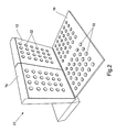
- the floor 16 of the luggage compartment 20 is provided with a plurality of anti-slip regions or pads 22.
- the pads 22 are arranged regularly across the surface of the floor 16 in a substantially grid-like pattern.
- Each pad 22 is generally circular, though this shape is not essential, and is formed from a material with a relatively high coefficient of friction.
- the pads 22 are made from a rubber material such as poly vinyl chloride (PVC).
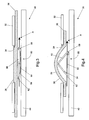
- FIGS 3 and 4 illustrate a cross section through a luggage compartment floor embodying a second form of the invention.
- the floor defining a load carrying surface and referred to generally at 16, comprises an upper support member in the form of a rigid or semi-rigid layer 32 formed from a plastics material such as ABS, PTFE, PP or PUV.
- the upper support member 32 has a plurality of circular apertures 34 extending therethrough, only one of which is shown in Figures 3 and 4.
- Beneath the rubber sheet 36 is disposed a lower support member in the form of a second, generally rigid board 40. It will be understood that the rubber sheet 36 is therefore sandwiched between the upper and lower support members 32, 40 and that, together, these make up the floor 16 of the luggage compartment defining the load carrying surface.
- a stop 62 is fixed to a point on the wire 60 beyond the second arm 54 so that when the wire 60 is pulled in a direction shown by the arrow A, the stop 62 exerts an axial force on the end of the second arm 54. Since the mechanism 50 is fixed in place relative to the board 40, the axial force applied to the mechanism 50 by the stop 62 causes the first and second arms 52, 54 to be pivoted upwardly thereby raising the thickened region 38 of the rubber sheet 36 through the corresponding aperture 34 in the upper support member, as shown in Figure 4. The thickened region 38 of the rubber sheet 36 therefore protrudes through the aperture 34 so that the upper surface 39 thereof is raised above the upper surface of the upper support member 32 and thus defines one of the raised, anti-slip pads 22 shown in Figure 2.
- the first and second arms 52, 54 return to their original position (shown in Figure 3) so that the pads 22 are no longer raised above the surface of the upper support member 32.
- the arms 52, 54 may be biased towards the first, non-use position shown in Figure 3 by means of springs or other resilient mechanisms. Alternatively, the weight of the objects carried in the luggage compartment may be sufficient to cause the pads to be lowered to the first position.
- the present invention addresses the problems associated with prior art systems by providing a load carrying surface for a vehicle luggage compartment which has a wipeable upper surface and a plurality of anti-slip pads disposed over the upper surface to reduce movement of objects supported by the surface.
- the pads are movable between a first, non-raised position in which they lie substantially flush with, or slightly below, the upper surface of the floor and a second position in which they are raised above the upper surface.
- the first position represents a loading condition in which the lower friction exhibited by the load carrying surface facilitates the loading of objects and luggage into the luggage compartment.
- the second position represents a load carrying position whereby the increased friction coefficient reduces or substantially prevents movement of objects across the luggage compartment floor whilst the vehicle is in motion.
- selected and/or individual pads 22 can be raised by drawing on the relevant wire. Drawing of the wire may be achieved by means of a handle, motor or any other suitable drive mechanism.
Landscapes
- Engineering & Computer Science (AREA)
- Mechanical Engineering (AREA)
- Transportation (AREA)
- Vehicle Step Arrangements And Article Storage (AREA)
- Passenger Equipment (AREA)
Applications Claiming Priority (2)
| Application Number | Priority Date | Filing Date | Title |
|---|---|---|---|
| GB0411743 | 2004-05-25 | ||
| GBGB0411743.8A GB0411743D0 (en) | 2004-05-25 | 2004-05-25 | Support apparatus |
Publications (2)
| Publication Number | Publication Date |
|---|---|
| EP1600329A2 true EP1600329A2 (fr) | 2005-11-30 |
| EP1600329A3 EP1600329A3 (fr) | 2006-08-02 |
Family
ID=32671085
Family Applications (1)
| Application Number | Title | Priority Date | Filing Date |
|---|---|---|---|
| EP05253203A Withdrawn EP1600329A3 (fr) | 2004-05-25 | 2005-05-25 | Dispositif de support |
Country Status (2)
| Country | Link |
|---|---|
| EP (1) | EP1600329A3 (fr) |
| GB (2) | GB0411743D0 (fr) |
Cited By (5)
| Publication number | Priority date | Publication date | Assignee | Title |
|---|---|---|---|---|
| DE102007061822A1 (de) * | 2007-12-20 | 2009-06-25 | GM Global Technology Operations, Inc., Detroit | Beladevorrichtung für Ladegut |
| DE102007061821A1 (de) * | 2007-12-20 | 2009-06-25 | GM Global Technology Operations, Inc., Detroit | Sicherungsvorrichtung für Ladegut |
| DE102014217545A1 (de) * | 2014-09-03 | 2016-03-03 | Bayerische Motoren Werke Aktiengesellschaft | Ladeboden für einen Laderaum eines Fahrzeugs |
| DE102019006692A1 (de) * | 2019-09-24 | 2021-03-25 | Daimler Ag | Gestaltungsvorrichtung zur variablen Gestaltung eines Innenraums eines Fahrzeugs sowie Fahrzeug |
| DE102022004060A1 (de) | 2022-10-31 | 2024-05-02 | Mercedes-Benz Group AG | Außenverkleidungsanordnung für ein Kraftfahrzeug, Kraftfahrzeug und Verfahren zum Betreiben einer Außenverkleidungsanordnung |
Family Cites Families (10)
| Publication number | Priority date | Publication date | Assignee | Title |
|---|---|---|---|---|
| US3669817A (en) * | 1970-03-16 | 1972-06-13 | James G Mcdevitt | Reversible flooring |
| CA2054042C (fr) * | 1991-10-23 | 1999-01-26 | Mario Primeau | Moquette reversible pour l'automobile |
| DE19514193C1 (de) * | 1995-04-15 | 1996-10-02 | Audi Ag | Sicherungseinrichtung für Ladegut in einem Fahrzeug |
| DE19546025C1 (de) * | 1995-12-09 | 1996-12-12 | Stefan Gabriel | Transportsicherungsplatte |
| DE19932323A1 (de) * | 1999-07-10 | 2001-01-11 | Rainer Berger | Pneumatische Ladegutfixierung |
| DE10013972A1 (de) * | 2000-03-21 | 2001-09-27 | Juergen Freigeber | Ladefläche mit integrierter, einstellbarer Rutschsicherung |
| GB2362614A (en) * | 2000-05-23 | 2001-11-28 | Magna Interior Sys Ltd | A reversible vehicle floor panel with rotatable bearing means |
| DE10055674A1 (de) * | 2000-11-10 | 2002-05-16 | Volkswagen Ag | Ladebodenanordnung für ein Fahrzeug |
| US20030015531A1 (en) * | 2001-07-17 | 2003-01-23 | Sangwon Choi | Reversible floor support |
| EP1422106B1 (fr) * | 2002-11-21 | 2008-10-08 | Ford Global Technologies, LLC | Dispositif de sécurisation de charge |
-
2004
- 2004-05-25 GB GBGB0411743.8A patent/GB0411743D0/en not_active Ceased
-
2005
- 2005-05-25 EP EP05253203A patent/EP1600329A3/fr not_active Withdrawn
- 2005-05-25 GB GB0510614A patent/GB2414457B/en not_active Expired - Fee Related
Non-Patent Citations (1)
| Title |
|---|
| None |
Cited By (7)
| Publication number | Priority date | Publication date | Assignee | Title |
|---|---|---|---|---|
| DE102007061822A1 (de) * | 2007-12-20 | 2009-06-25 | GM Global Technology Operations, Inc., Detroit | Beladevorrichtung für Ladegut |
| DE102007061821A1 (de) * | 2007-12-20 | 2009-06-25 | GM Global Technology Operations, Inc., Detroit | Sicherungsvorrichtung für Ladegut |
| DE102014217545A1 (de) * | 2014-09-03 | 2016-03-03 | Bayerische Motoren Werke Aktiengesellschaft | Ladeboden für einen Laderaum eines Fahrzeugs |
| DE102014217545B4 (de) * | 2014-09-03 | 2025-03-13 | Bayerische Motoren Werke Aktiengesellschaft | Ladeboden für einen Laderaum eines Fahrzeugs |
| DE102019006692A1 (de) * | 2019-09-24 | 2021-03-25 | Daimler Ag | Gestaltungsvorrichtung zur variablen Gestaltung eines Innenraums eines Fahrzeugs sowie Fahrzeug |
| DE102019006692B4 (de) | 2019-09-24 | 2021-07-15 | Daimler Ag | Gestaltungsvorrichtung zur variablen Gestaltung eines Innenraums eines Fahrzeugs sowie Fahrzeug |
| DE102022004060A1 (de) | 2022-10-31 | 2024-05-02 | Mercedes-Benz Group AG | Außenverkleidungsanordnung für ein Kraftfahrzeug, Kraftfahrzeug und Verfahren zum Betreiben einer Außenverkleidungsanordnung |
Also Published As
| Publication number | Publication date |
|---|---|
| GB2414457A (en) | 2005-11-30 |
| GB2414457B (en) | 2006-07-12 |
| EP1600329A3 (fr) | 2006-08-02 |
| GB0411743D0 (en) | 2004-06-30 |
| GB0510614D0 (en) | 2005-06-29 |
Similar Documents
| Publication | Publication Date | Title |
|---|---|---|
| US6390547B1 (en) | Seat assembly | |
| US8714655B2 (en) | Rear seat divider for motor vehicle | |
| US20060180623A1 (en) | Rear vehicle storage system | |
| US7527314B2 (en) | Vehicle gap guard | |
| US7201421B2 (en) | Rear vehicle storage system | |
| US20080179926A1 (en) | Mat Made of Flexible, Closed-Cell, Expanded Thermoplastic for Protecting a Car Seat from Pets | |
| CN101274602B (zh) | 具有附件系统的交通工具座椅组件及其制造方法 | |
| US6981730B2 (en) | Seat storage system | |
| US7628438B2 (en) | Rear seat cushion underside storage flap | |
| US6406085B1 (en) | Removable bi-section cargo cover system | |
| US6732895B2 (en) | Integrated storage apparatus for vehicle cargo compartments | |
| CN103287295B (zh) | 具有储藏部的头部约束件 | |
| US5372396A (en) | Invertible cargo bed liner | |
| US5975610A (en) | Seating apparatus for a tailgate | |
| EP1600329A2 (fr) | Dispositif de support | |
| JP3605578B2 (ja) | 自動車の延長マット配設構造 | |
| WO2013039497A1 (fr) | Séparateur de siège arrière pour véhicule à moteur | |
| US20250256625A1 (en) | An apparatus for a vehicle loadspace of a vehicle | |
| US20080142560A1 (en) | Grocery bag bar and holding system | |
| US7399032B2 (en) | Multi purpose seat back protecting panel | |
| JP2815323B2 (ja) | トレイ付きマット | |
| US7007997B1 (en) | Removable stanchion cover | |
| US20050092794A1 (en) | Non-slip vehicle article container | |
| JP4640638B2 (ja) | 車両の荷室構造 | |
| CZ38367U1 (cs) | Podložka pro zavazadlový prostor automobilu a automobil s touto podložkou |
Legal Events
| Date | Code | Title | Description |
|---|---|---|---|
| PUAI | Public reference made under article 153(3) epc to a published international application that has entered the european phase |
Free format text: ORIGINAL CODE: 0009012 |
|
| AK | Designated contracting states |
Kind code of ref document: A2 Designated state(s): AT BE BG CH CY CZ DE DK EE ES FI FR GB GR HU IE IS IT LI LT LU MC NL PL PT RO SE SI SK TR |
|
| AX | Request for extension of the european patent |
Extension state: AL BA HR LV MK YU |
|
| PUAL | Search report despatched |
Free format text: ORIGINAL CODE: 0009013 |
|
| AK | Designated contracting states |
Kind code of ref document: A3 Designated state(s): AT BE BG CH CY CZ DE DK EE ES FI FR GB GR HU IE IS IT LI LT LU MC NL PL PT RO SE SI SK TR |
|
| AX | Request for extension of the european patent |
Extension state: AL BA HR LV MK YU |
|
| 17P | Request for examination filed |
Effective date: 20060816 |
|
| RAP1 | Party data changed (applicant data changed or rights of an application transferred) |
Owner name: NISSAN MOTOR MANUFACTURING (UK) LTD. |
|
| AKX | Designation fees paid |
Designated state(s): DE FR GB |
|
| STAA | Information on the status of an ep patent application or granted ep patent |
Free format text: STATUS: THE APPLICATION IS DEEMED TO BE WITHDRAWN |
|
| 18D | Application deemed to be withdrawn |
Effective date: 20101201 |