EP1600737A2 - Vorrichtung zur rotativen Winkelmessung - Google Patents
Vorrichtung zur rotativen Winkelmessung Download PDFInfo
- Publication number
- EP1600737A2 EP1600737A2 EP05010918A EP05010918A EP1600737A2 EP 1600737 A2 EP1600737 A2 EP 1600737A2 EP 05010918 A EP05010918 A EP 05010918A EP 05010918 A EP05010918 A EP 05010918A EP 1600737 A2 EP1600737 A2 EP 1600737A2
- Authority
- EP
- European Patent Office
- Prior art keywords
- magnetic field
- disc
- signal
- angle
- disk
- Prior art date
- Legal status (The legal status is an assumption and is not a legal conclusion. Google has not performed a legal analysis and makes no representation as to the accuracy of the status listed.)
- Granted
Links
- 238000005259 measurement Methods 0.000 title claims abstract description 12
- 239000004753 textile Substances 0.000 claims abstract description 3
- 239000004020 conductor Substances 0.000 claims abstract 2
- 230000005415 magnetization Effects 0.000 claims description 10
- 238000011156 evaluation Methods 0.000 claims description 5
- 230000000737 periodic effect Effects 0.000 claims description 4
- 230000003993 interaction Effects 0.000 claims description 3
- 238000009776 industrial production Methods 0.000 description 3
- 238000001514 detection method Methods 0.000 description 2
- 239000000243 solution Substances 0.000 description 2
- 239000003637 basic solution Substances 0.000 description 1
- 230000005540 biological transmission Effects 0.000 description 1
- 238000011161 development Methods 0.000 description 1
- 230000018109 developmental process Effects 0.000 description 1
- 230000002349 favourable effect Effects 0.000 description 1
- 230000004907 flux Effects 0.000 description 1
Images
Classifications
-
- G—PHYSICS
- G01—MEASURING; TESTING
- G01D—MEASURING NOT SPECIALLY ADAPTED FOR A SPECIFIC VARIABLE; ARRANGEMENTS FOR MEASURING TWO OR MORE VARIABLES NOT COVERED IN A SINGLE OTHER SUBCLASS; TARIFF METERING APPARATUS; MEASURING OR TESTING NOT OTHERWISE PROVIDED FOR
- G01D5/00—Mechanical means for transferring the output of a sensing member; Means for converting the output of a sensing member to another variable where the form or nature of the sensing member does not constrain the means for converting; Transducers not specially adapted for a specific variable
- G01D5/12—Mechanical means for transferring the output of a sensing member; Means for converting the output of a sensing member to another variable where the form or nature of the sensing member does not constrain the means for converting; Transducers not specially adapted for a specific variable using electric or magnetic means
- G01D5/14—Mechanical means for transferring the output of a sensing member; Means for converting the output of a sensing member to another variable where the form or nature of the sensing member does not constrain the means for converting; Transducers not specially adapted for a specific variable using electric or magnetic means influencing the magnitude of a current or voltage
- G01D5/142—Mechanical means for transferring the output of a sensing member; Means for converting the output of a sensing member to another variable where the form or nature of the sensing member does not constrain the means for converting; Transducers not specially adapted for a specific variable using electric or magnetic means influencing the magnitude of a current or voltage using Hall-effect devices
- G01D5/145—Mechanical means for transferring the output of a sensing member; Means for converting the output of a sensing member to another variable where the form or nature of the sensing member does not constrain the means for converting; Transducers not specially adapted for a specific variable using electric or magnetic means influencing the magnitude of a current or voltage using Hall-effect devices influenced by the relative movement between the Hall device and magnetic fields
-
- G—PHYSICS
- G01—MEASURING; TESTING
- G01D—MEASURING NOT SPECIALLY ADAPTED FOR A SPECIFIC VARIABLE; ARRANGEMENTS FOR MEASURING TWO OR MORE VARIABLES NOT COVERED IN A SINGLE OTHER SUBCLASS; TARIFF METERING APPARATUS; MEASURING OR TESTING NOT OTHERWISE PROVIDED FOR
- G01D5/00—Mechanical means for transferring the output of a sensing member; Means for converting the output of a sensing member to another variable where the form or nature of the sensing member does not constrain the means for converting; Transducers not specially adapted for a specific variable
- G01D5/12—Mechanical means for transferring the output of a sensing member; Means for converting the output of a sensing member to another variable where the form or nature of the sensing member does not constrain the means for converting; Transducers not specially adapted for a specific variable using electric or magnetic means
- G01D5/14—Mechanical means for transferring the output of a sensing member; Means for converting the output of a sensing member to another variable where the form or nature of the sensing member does not constrain the means for converting; Transducers not specially adapted for a specific variable using electric or magnetic means influencing the magnitude of a current or voltage
- G01D5/142—Mechanical means for transferring the output of a sensing member; Means for converting the output of a sensing member to another variable where the form or nature of the sensing member does not constrain the means for converting; Transducers not specially adapted for a specific variable using electric or magnetic means influencing the magnitude of a current or voltage using Hall-effect devices
- G01D5/147—Mechanical means for transferring the output of a sensing member; Means for converting the output of a sensing member to another variable where the form or nature of the sensing member does not constrain the means for converting; Transducers not specially adapted for a specific variable using electric or magnetic means influencing the magnitude of a current or voltage using Hall-effect devices influenced by the movement of a third element, the position of Hall device and the source of magnetic field being fixed in respect to each other
-
- G—PHYSICS
- G01—MEASURING; TESTING
- G01D—MEASURING NOT SPECIALLY ADAPTED FOR A SPECIFIC VARIABLE; ARRANGEMENTS FOR MEASURING TWO OR MORE VARIABLES NOT COVERED IN A SINGLE OTHER SUBCLASS; TARIFF METERING APPARATUS; MEASURING OR TESTING NOT OTHERWISE PROVIDED FOR
- G01D5/00—Mechanical means for transferring the output of a sensing member; Means for converting the output of a sensing member to another variable where the form or nature of the sensing member does not constrain the means for converting; Transducers not specially adapted for a specific variable
- G01D5/12—Mechanical means for transferring the output of a sensing member; Means for converting the output of a sensing member to another variable where the form or nature of the sensing member does not constrain the means for converting; Transducers not specially adapted for a specific variable using electric or magnetic means
- G01D5/244—Mechanical means for transferring the output of a sensing member; Means for converting the output of a sensing member to another variable where the form or nature of the sensing member does not constrain the means for converting; Transducers not specially adapted for a specific variable using electric or magnetic means influencing characteristics of pulses or pulse trains; generating pulses or pulse trains
- G01D5/245—Mechanical means for transferring the output of a sensing member; Means for converting the output of a sensing member to another variable where the form or nature of the sensing member does not constrain the means for converting; Transducers not specially adapted for a specific variable using electric or magnetic means influencing characteristics of pulses or pulse trains; generating pulses or pulse trains using a variable number of pulses in a train
- G01D5/2451—Incremental encoders
-
- G—PHYSICS
- G01—MEASURING; TESTING
- G01D—MEASURING NOT SPECIALLY ADAPTED FOR A SPECIFIC VARIABLE; ARRANGEMENTS FOR MEASURING TWO OR MORE VARIABLES NOT COVERED IN A SINGLE OTHER SUBCLASS; TARIFF METERING APPARATUS; MEASURING OR TESTING NOT OTHERWISE PROVIDED FOR
- G01D2205/00—Indexing scheme relating to details of means for transferring or converting the output of a sensing member
- G01D2205/70—Position sensors comprising a moving target with particular shapes, e.g. of soft magnetic targets
- G01D2205/73—Targets mounted eccentrically with respect to the axis of rotation
Definitions
- the present invention relates to a rotary device Angle measurement according to the preamble of the main claim.
- Such a device is known from DE 196 29 611 A1 and describes an arrangement in which an eccentric mounted disc as a control disc for the purpose of Angle measurement with at least two laterally over one (due to the eccentricity) variable air gap with the interacts magnetically conductive disc and so a one current rotational position of the disc relative to the magnetic field sensors generates corresponding angle signal.
- Magnetic field detectors a Hall sensor (typically in chip form), which together with a so-called Bias or bias magnets in a common (typically magnetic shielding) housing sitting.
- the bias magnet generates a in the control disk magnetic flux, which in turn from the Hall element is scanned.
- an (absolute) angle measurement of the current Position of the control disc perform, which by the generated at least two magnetic field detectors, typically sinusoidal signal in combination an angle determination over the entire 360 ° circumference of the control disk allows.
- such devices are characterized the state of the art by the ability of the intended Angle measurement even with very high rotational speeds (and associated high cutoff frequencies) too enable.
- the object of the present invention is therefore to provide a generic, For example, from DE 196 29 611 known Device with regard to its evaluation quality and thus also to improve their angular resolution, where In particular, an improved device can be provided which is also for use in industrial Production environments are suitable and reproducible, resilient Delivers results.
- the invention provides torsionally rigid (and thus angle stable with the conventional non-contact scanned control disc) another magnetized edge
- a disc which by their marginal magnetization and in the Interaction with a purpose assigned to it second magnetic field detector creates a possibility that Resolution and thus the signal quality of the overall arrangement significantly increase.
- the second magnetic field detector generated second angle signal which is preferably periodic in the context of the invention (in turn, by appropriate magnetization of the second Disk is reached) the possibility in the way of a Overlay or parallel evaluation with the first Angle signal to arrive at a combined output signal which is high-resolution and reproducible in both directions of rotation is; this also with little equipment.
- the first angle signal an absolute signal and the second angle signal preferably an incremental signal, wherein a conventional Angular resolution of the first angle signal in the range between about 6 and 13 bits (corresponding to 64 to about 8000 Angle sections) by the second angle signal to further 1 to 13 bit resolution can be improved; the approximately in industrial applications of resolvers required Resolution of 1 million / revolution thus becomes significant exceeded.
- an MR sensor is used, which high signal quality (i.e., low noise and clinking) at a reasonable cost; in Generically known manner, the first magnetic field sensors (which typically in the radial direction by 90 ° spaced) are designed as Hall sensors.
- a preferred embodiment of the invention also provides before, all magnetic field detectors in a common (preferred manually manageable or easy to move and assemble) Integrate housing, wherein it is further preferred Here has been found to be cheap, to interact with the combination of control disc and second Disc the housing to a housing section with a extending according to the radius of curvature of the discs, to provide curved or angled end face, so that in this respect suitable air gaps for non-contact Magnetic field detection realized by the magnetic field detectors can be.
- This sensor housing (which is more preferred) may be suitable in addition to the magnetic field detectors and the associated Transmitter contains) wireless or wired with downstream units, eg. B. a control unit for a machine tool communicate, preferred for this purpose implemented common digital interface protocols become.
- any inhomogeneous (i.e. Magnetization in the edge region of the second magnetic disk is suitable, so it offers here in the context of the present invention as favorable on, this magnetization periodically, and more preferably provide sinusoidal or digital, so that in otherwise known manner on the more preferably used MR sensor produces a high quality second angle signal can be.
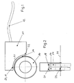
- a sensor housing 10 of an i.w. has cuboidal contour, As shown in the plan view of Fig. 1, a curved Housing section 11, whose end face a pair of magnetized discs 14, 16 faces. More accurate said is a first, concentric on a rotation axis 24 mounted eccentric magnetic disk 16 in known (and for example as described in DE 196 29 611) Way as Drehwinkelaufsacrificing about the axis of rotation 24th connected to a rotary encoder, not shown, and acts magnetic with a pair of mutually 90 ° out of phase Hall sensors 20, 22 as first magnetic field detectors together, which are each end of the curved Housing section 12 in the housing interior of the housing 10th are located.
- Hall sensors 20, 22 detect during rotation of the eccentric 16 slice the different distances between Disk edge and Hall sensor 20 and 22 and generate on this way a suitable with an evaluation in the Housing 10 to be evaluated sinusoidal or cosinusoidal angle signal (First angle signal in the sense of the invention, resolution about 6 to a maximum of 13 bits).
- a second magnetic disc 14 which peripherally along its circumference with a periodic Magnetization, here a digital magnetization, is provided.
- This magnetization is in turn contactless sampled by a second magnetic field detector 18, which in the described embodiment as MR magnetic field detector is formed and in the housing 10 the first Hall sensor 20 is provided adjacent.
- the digital magnetization of the second disc 14 MR sensor 18 generates a periodic output signal as a second angle signal (resolution approx. 1 to 13 bit), which can be suitably digitized or quantized and together with the first angle signal of the pair of Hall sensors 20, 22 to a high-resolution angle signal charged as output of the overall device or is combined, so that a maximum resolution of 26 bit per revolution can be achieved as an absolute signal. More accurate said ensures the rigid angle and thus fixed relative position the first disc 16 and the second disc 14 for that too between these two electrical Output signals has a fixed relative relationship, so that to improve the output quality of the overall signal the combination can be done.
- the present invention is not limited to those described Embodiment limited; so are any variants of illustrated configuration conceivable, started with the magnetization the involved discs 14, 16 on the housing form until use and interconnection of each used magnetic field detectors.
Landscapes
- Physics & Mathematics (AREA)
- General Physics & Mathematics (AREA)
- Transmission And Conversion Of Sensor Element Output (AREA)
- Measurement Of Length, Angles, Or The Like Using Electric Or Magnetic Means (AREA)
Abstract
Description
- Fig. 1:
- eine Draufsicht auf die erfindungsgemäße Vorrichtung zur rotativen winkelmessung gemäß einer ersten bevorzugten Ausführungsform und
- Fig. 2:
- eine Seitenansicht auf die Anordnung gemäß Fig. 1.
Claims (10)
- Vorrichtung zur rotativen Winkelmessung mit einer exzentrisch auf einer Rotationsachse (24) gelagerten Scheibe (16) als Steuerscheibe aus magnetisch leitendem Material, die zum berührungslosen magnetischen Zusammenwirken mit einer Mehrzahl von extern der Scheibe vorgesehenen ersten Magnetfelddetektoren (20, 22) ausgebildet und angeordnet ist,
die jeweils einen Bias-Magneten aufweisen und zum Erzeugen eines elektronisch auswertbaren, durch einen Abstand zwischen der Scheibe und einem jeweiligen der ersten Magnetfelddetektoren bestimmten ersten Winkelsignals eingerichtet sind,
dadurch gekennzeichnet, dass
auf der Rotationsachse der Steuerscheibe (16) benachbart eine zumindest randseitig inhomogen magnetisierte zweite Scheibe (14) konzentrisch vorgesehen, mit der Steuerscheibe winkelstabil um die Rotationsachse verbunden und zum berührungslosen magnetischen Zusammenwirken mit einem zweiten Magnetfelddetektor (18) ausgebildet ist,
wobei ein elektronisches Signal des zweiten Magnetfelddetektors zum Erzeugen eines zweiten Winkelsignals, insbesondere eines eine Winkelauflösung des ersten Winkelsignals erhöhenden Ausgangssignals der Vorrichtung, auswert- und verarbeitbar ist. - Vorrichtung nach Anspruch 1, dadurch gekennzeichnet, dass die ersten Magnetfelddetektoren zwei in einem umfangsmäßigen 90°-Winkel zueinander angeordnete Hall-Sensoren (20, 22) sind, die bevorzugt zum Erzeugen eines sinus- bzw. kosinusförmigen ersten Winkelsignals beschaltet sind.
- Vorrichtung nach Anspruch 1 oder 2, dadurch gekennzeichnet, dass der zweite Magnetfelddetektor (18) ein MR-Sensor ist.
- Vorrichtung nach einem der Ansprüche 1 bis 3, dadurch gekennzeichnet, dass die ersten Magnetfelddetektoren und der zweite Magnetfelddetektor in ein gemeinsames Sensorgehäuse (10) integriert sind.
- Vorrichtung nach Anspruch 4, dadurch gekennzeichnet, dass das Sensorgehäuse eine Auswerteelektronik für das erste und das zweite Winkelsignal sowie das Ausgangssignal der Vorrichtung und bevorzugt eine digitale Schnittstellenelektronik aufweist.
- Vorrichtung nach einem der Ansprüche 1 bis 5, dadurch gekennzeichnet, dass das Sensorgehäuse zum berührungslosen seitlichen Zusammenwirken mit der Steuerscheibe (16) und der zweiten Scheibe (14) ausgebildet ist und einen einem Umfangsradius der Steuerscheibe und/oder der zweiten Scheibe folgendem gekrümmten oder abgewinkelten Gehäuseabschnitt (11) aufweist.
- Vorrichtung nach einem der Ansprüche 4 bis 6, dadurch gekennzeichnet, dass das Sensorgehäuse drahtlos oder über ein Signalkabel (12) mit nachgeschalteten Aggregaten verbindbar ist.
- Vorrichtung nach einem der Ansprüche 4 bis 7, dadurch gekennzeichnet, dass einer der ersten Magnetfelddetektoren sowie der zweite Magnetfelddetektor in axialer Richtung der Rotationsachse im Sensorgehäuse zueinander benachbart angeordnet sind.
- Vorrichtung nach einem der Ansprüche 1 bis 8, dadurch gekennzeichnet, dass die zweite Scheibe randseitig eine periodische, insbesondere sinusförmige oder digitale, Codierung als inhomogene Magnetisierung aufweist.
- Verwendung der Vorrichtung nach einem der Ansprüche 1 bis 9 zur Rotationsmessung einer Antriebswelle einer maschinellen Antriebseinheit, insbesondere für eine Werkzeugmaschine, eine Druck- oder Textilmaschine.
Applications Claiming Priority (2)
| Application Number | Priority Date | Filing Date | Title |
|---|---|---|---|
| DE102004026476A DE102004026476A1 (de) | 2004-05-27 | 2004-05-27 | Vorrichtung zur rotativen Winkelmessung |
| DE102004026476 | 2004-05-27 |
Publications (3)
| Publication Number | Publication Date |
|---|---|
| EP1600737A2 true EP1600737A2 (de) | 2005-11-30 |
| EP1600737A3 EP1600737A3 (de) | 2008-03-19 |
| EP1600737B1 EP1600737B1 (de) | 2016-03-23 |
Family
ID=34981165
Family Applications (1)
| Application Number | Title | Priority Date | Filing Date |
|---|---|---|---|
| EP05010918.0A Expired - Lifetime EP1600737B1 (de) | 2004-05-27 | 2005-05-20 | Vorrichtung zur rotativen Winkelmessung |
Country Status (2)
| Country | Link |
|---|---|
| EP (1) | EP1600737B1 (de) |
| DE (1) | DE102004026476A1 (de) |
Cited By (2)
| Publication number | Priority date | Publication date | Assignee | Title |
|---|---|---|---|---|
| WO2008060801A1 (en) | 2006-11-14 | 2008-05-22 | Raytheon Company | Angular position measurement device |
| EP2068124A1 (de) * | 2007-12-04 | 2009-06-10 | Metris IPR N.V. | Gelenkarm-Messgerät mit mehreren Messscheiben |
Families Citing this family (4)
| Publication number | Priority date | Publication date | Assignee | Title |
|---|---|---|---|---|
| DE102007011675A1 (de) * | 2006-12-22 | 2008-06-26 | Zf Lenksysteme Gmbh | Lenkwinkel- und Drehmomentsensor in einer Hilfskraftlenkung eines Kraftfahrzeugs |
| DE102008045677A1 (de) * | 2008-09-04 | 2010-03-18 | Horst Siedle Gmbh & Co. Kg | Kontaktloser Tankstandsensor |
| DE102020128727B3 (de) | 2020-11-02 | 2021-11-25 | Sick Ag | Drehgeber und Verfahren zur Bestimmung einer Winkelposition |
| DE102021102053B4 (de) | 2021-01-29 | 2025-04-24 | Sick Ag | Bestimmung einer Position |
Citations (3)
| Publication number | Priority date | Publication date | Assignee | Title |
|---|---|---|---|---|
| US4785242A (en) | 1986-12-15 | 1988-11-15 | Sundstrand Corporation | Position detecting apparatus using multiple magnetic sensors for determining relative and absolute angular position |
| DE4307544A1 (de) | 1993-03-10 | 1994-09-15 | Siemens Ag | Anordnung zur Erfassung der Drehstellung eines Rotationskörpers |
| DE4400616A1 (de) | 1994-01-12 | 1995-07-13 | Vdo Schindling | Magnetischer Positionssensor, insbesondere für Kraftfahrzeuge |
-
2004
- 2004-05-27 DE DE102004026476A patent/DE102004026476A1/de not_active Withdrawn
-
2005
- 2005-05-20 EP EP05010918.0A patent/EP1600737B1/de not_active Expired - Lifetime
Patent Citations (3)
| Publication number | Priority date | Publication date | Assignee | Title |
|---|---|---|---|---|
| US4785242A (en) | 1986-12-15 | 1988-11-15 | Sundstrand Corporation | Position detecting apparatus using multiple magnetic sensors for determining relative and absolute angular position |
| DE4307544A1 (de) | 1993-03-10 | 1994-09-15 | Siemens Ag | Anordnung zur Erfassung der Drehstellung eines Rotationskörpers |
| DE4400616A1 (de) | 1994-01-12 | 1995-07-13 | Vdo Schindling | Magnetischer Positionssensor, insbesondere für Kraftfahrzeuge |
Cited By (3)
| Publication number | Priority date | Publication date | Assignee | Title |
|---|---|---|---|---|
| WO2008060801A1 (en) | 2006-11-14 | 2008-05-22 | Raytheon Company | Angular position measurement device |
| US7550965B2 (en) | 2006-11-14 | 2009-06-23 | Raytheon Company | Angular position measurement device |
| EP2068124A1 (de) * | 2007-12-04 | 2009-06-10 | Metris IPR N.V. | Gelenkarm-Messgerät mit mehreren Messscheiben |
Also Published As
| Publication number | Publication date |
|---|---|
| EP1600737B1 (de) | 2016-03-23 |
| DE102004026476A1 (de) | 2005-12-22 |
| EP1600737A3 (de) | 2008-03-19 |
Similar Documents
| Publication | Publication Date | Title |
|---|---|---|
| DE102009044542B3 (de) | Wälzlager mit einer Sensoreinheit | |
| WO2021069014A1 (de) | Sensorvorrichtung zur erfassung der drehwinkelstellung einer drehbeweglichen welle sowie lenkungsanordnung eines fahrzeugs | |
| EP2225142B1 (de) | Absolut messende lenkwinkelsensoranordnung | |
| EP2929297B1 (de) | Sensorvorrichtung zur bestimmung mindestens einer rotationseigenschaft eines rotierenden elements | |
| EP2420803A1 (de) | Vorrichtung zum Erfassen des Verdrehwinkels einer Welle und /oder eines an der Welle auftretenden Drehmoments und Verfahren zum Betreiben der Vorrichtung | |
| EP1408305A2 (de) | Vorrichtung zum Erfassen des Absolutwinkels einer Welle | |
| EP2748053A1 (de) | Kombinierter lenkmoment-lenkwinkelsensor | |
| EP3207337B1 (de) | Sensor zur bestimmung mindestens einer rotationseigenschaft eines rotierenden elements | |
| DE10036281A1 (de) | Vorrichtung zur Messung eines Drehwinkels an einer Drehachse | |
| DE102018211216A1 (de) | Geberradanordnung und Verfahren zum Ermitteln einer Absolutwinkelposition und einer Drehrichtung | |
| DE102013205901B4 (de) | Schaltvorrichtung eines Fahrzeuggangräderwechselgetriebes | |
| EP2255207A2 (de) | Winkelmesssystem und verfahren zur herstellung eines winkelmesssystems | |
| DE102004001570B4 (de) | Messverfahren sowie Messvorrichtung zum Durchführen des Messverfahrens | |
| EP1600737B1 (de) | Vorrichtung zur rotativen Winkelmessung | |
| WO2015062592A1 (de) | Sensorsystem zur drehzahlmessung mit einem polrad mit linearisiertem magnetfeld | |
| EP2392899A2 (de) | Zahnraddrehgeber | |
| EP2257768B1 (de) | Winkelmesssystem | |
| DE102012221327A1 (de) | Sensorvorrichtung zur Bestimmung mindestens einer Rotationseigenschaft eines rotierenden Elements | |
| DE102005061347A1 (de) | Anordnung zur Messung des absoluten Drehwinkels einer Welle | |
| DE4103561C2 (de) | Drehstellungsgeber für die Erfassung einer Rotorposition | |
| EP3583388B1 (de) | Sensoreinrichtung | |
| EP1939592A1 (de) | Vorrichtung zur Detektion der absoluten Winkellage einer Drehachse | |
| EP3128294A2 (de) | Sensor zur bestimmung der winkelposition eines motors sowie ein motor mit einem sensor zur bestimmung der winkelposition | |
| EP3851821A1 (de) | Elastomerkörper sowie messanordnung an demselben | |
| EP2281125A2 (de) | Lagervorrichtung mit positionsgeber |
Legal Events
| Date | Code | Title | Description |
|---|---|---|---|
| PUAI | Public reference made under article 153(3) epc to a published international application that has entered the european phase |
Free format text: ORIGINAL CODE: 0009012 |
|
| AK | Designated contracting states |
Kind code of ref document: A2 Designated state(s): AT BE BG CH CY CZ DE DK EE ES FI FR GB GR HU IE IS IT LI LT LU MC NL PL PT RO SE SI SK TR |
|
| AX | Request for extension of the european patent |
Extension state: AL BA HR LV MK YU |
|
| PUAL | Search report despatched |
Free format text: ORIGINAL CODE: 0009013 |
|
| AK | Designated contracting states |
Kind code of ref document: A3 Designated state(s): AT BE BG CH CY CZ DE DK EE ES FI FR GB GR HU IE IS IT LI LT LU MC NL PL PT RO SE SI SK TR |
|
| AX | Request for extension of the european patent |
Extension state: AL BA HR LV MK YU |
|
| 17P | Request for examination filed |
Effective date: 20080918 |
|
| 17Q | First examination report despatched |
Effective date: 20081023 |
|
| AKX | Designation fees paid |
Designated state(s): AT BE BG CH CY CZ DE DK EE ES FI FR GB GR HU IE IS IT LI LT LU MC NL PL PT RO SE SI SK TR |
|
| RAP1 | Party data changed (applicant data changed or rights of an application transferred) |
Owner name: ELGO-ELECTRONIC GMBH & CO. KG |
|
| GRAP | Despatch of communication of intention to grant a patent |
Free format text: ORIGINAL CODE: EPIDOSNIGR1 |
|
| INTG | Intention to grant announced |
Effective date: 20151127 |
|
| GRAS | Grant fee paid |
Free format text: ORIGINAL CODE: EPIDOSNIGR3 |
|
| GRAA | (expected) grant |
Free format text: ORIGINAL CODE: 0009210 |
|
| AK | Designated contracting states |
Kind code of ref document: B1 Designated state(s): AT BE BG CH CY CZ DE DK EE ES FI FR GB GR HU IE IS IT LI LT LU MC NL PL PT RO SE SI SK TR |
|
| REG | Reference to a national code |
Ref country code: GB Ref legal event code: FG4D Free format text: NOT ENGLISH |
|
| REG | Reference to a national code |
Ref country code: CH Ref legal event code: EP |
|
| REG | Reference to a national code |
Ref country code: AT Ref legal event code: REF Ref document number: 783610 Country of ref document: AT Kind code of ref document: T Effective date: 20160415 |
|
| REG | Reference to a national code |
Ref country code: IE Ref legal event code: FG4D Free format text: LANGUAGE OF EP DOCUMENT: GERMAN |
|
| REG | Reference to a national code |
Ref country code: DE Ref legal event code: R096 Ref document number: 502005015156 Country of ref document: DE |
|
| REG | Reference to a national code |
Ref country code: LT Ref legal event code: MG4D |
|
| REG | Reference to a national code |
Ref country code: NL Ref legal event code: MP Effective date: 20160323 |
|
| PG25 | Lapsed in a contracting state [announced via postgrant information from national office to epo] |
Ref country code: FI Free format text: LAPSE BECAUSE OF FAILURE TO SUBMIT A TRANSLATION OF THE DESCRIPTION OR TO PAY THE FEE WITHIN THE PRESCRIBED TIME-LIMIT Effective date: 20160323 Ref country code: GR Free format text: LAPSE BECAUSE OF FAILURE TO SUBMIT A TRANSLATION OF THE DESCRIPTION OR TO PAY THE FEE WITHIN THE PRESCRIBED TIME-LIMIT Effective date: 20160624 |
|
| PG25 | Lapsed in a contracting state [announced via postgrant information from national office to epo] |
Ref country code: NL Free format text: LAPSE BECAUSE OF FAILURE TO SUBMIT A TRANSLATION OF THE DESCRIPTION OR TO PAY THE FEE WITHIN THE PRESCRIBED TIME-LIMIT Effective date: 20160323 Ref country code: LT Free format text: LAPSE BECAUSE OF FAILURE TO SUBMIT A TRANSLATION OF THE DESCRIPTION OR TO PAY THE FEE WITHIN THE PRESCRIBED TIME-LIMIT Effective date: 20160323 Ref country code: SE Free format text: LAPSE BECAUSE OF FAILURE TO SUBMIT A TRANSLATION OF THE DESCRIPTION OR TO PAY THE FEE WITHIN THE PRESCRIBED TIME-LIMIT Effective date: 20160323 Ref country code: BE Free format text: LAPSE BECAUSE OF NON-PAYMENT OF DUE FEES Effective date: 20160531 |
|
| PG25 | Lapsed in a contracting state [announced via postgrant information from national office to epo] |
Ref country code: EE Free format text: LAPSE BECAUSE OF FAILURE TO SUBMIT A TRANSLATION OF THE DESCRIPTION OR TO PAY THE FEE WITHIN THE PRESCRIBED TIME-LIMIT Effective date: 20160323 Ref country code: PL Free format text: LAPSE BECAUSE OF FAILURE TO SUBMIT A TRANSLATION OF THE DESCRIPTION OR TO PAY THE FEE WITHIN THE PRESCRIBED TIME-LIMIT Effective date: 20160323 Ref country code: IS Free format text: LAPSE BECAUSE OF FAILURE TO SUBMIT A TRANSLATION OF THE DESCRIPTION OR TO PAY THE FEE WITHIN THE PRESCRIBED TIME-LIMIT Effective date: 20160723 |
|
| PG25 | Lapsed in a contracting state [announced via postgrant information from national office to epo] |
Ref country code: RO Free format text: LAPSE BECAUSE OF FAILURE TO SUBMIT A TRANSLATION OF THE DESCRIPTION OR TO PAY THE FEE WITHIN THE PRESCRIBED TIME-LIMIT Effective date: 20160323 Ref country code: PT Free format text: LAPSE BECAUSE OF FAILURE TO SUBMIT A TRANSLATION OF THE DESCRIPTION OR TO PAY THE FEE WITHIN THE PRESCRIBED TIME-LIMIT Effective date: 20160725 Ref country code: CZ Free format text: LAPSE BECAUSE OF FAILURE TO SUBMIT A TRANSLATION OF THE DESCRIPTION OR TO PAY THE FEE WITHIN THE PRESCRIBED TIME-LIMIT Effective date: 20160323 Ref country code: SK Free format text: LAPSE BECAUSE OF FAILURE TO SUBMIT A TRANSLATION OF THE DESCRIPTION OR TO PAY THE FEE WITHIN THE PRESCRIBED TIME-LIMIT Effective date: 20160323 Ref country code: ES Free format text: LAPSE BECAUSE OF FAILURE TO SUBMIT A TRANSLATION OF THE DESCRIPTION OR TO PAY THE FEE WITHIN THE PRESCRIBED TIME-LIMIT Effective date: 20160323 |
|
| PG25 | Lapsed in a contracting state [announced via postgrant information from national office to epo] |
Ref country code: LU Free format text: LAPSE BECAUSE OF FAILURE TO SUBMIT A TRANSLATION OF THE DESCRIPTION OR TO PAY THE FEE WITHIN THE PRESCRIBED TIME-LIMIT Effective date: 20160520 Ref country code: IT Free format text: LAPSE BECAUSE OF FAILURE TO SUBMIT A TRANSLATION OF THE DESCRIPTION OR TO PAY THE FEE WITHIN THE PRESCRIBED TIME-LIMIT Effective date: 20160323 |
|
| REG | Reference to a national code |
Ref country code: CH Ref legal event code: PL |
|
| REG | Reference to a national code |
Ref country code: DE Ref legal event code: R097 Ref document number: 502005015156 Country of ref document: DE |
|
| PLBE | No opposition filed within time limit |
Free format text: ORIGINAL CODE: 0009261 |
|
| STAA | Information on the status of an ep patent application or granted ep patent |
Free format text: STATUS: NO OPPOSITION FILED WITHIN TIME LIMIT |
|
| PG25 | Lapsed in a contracting state [announced via postgrant information from national office to epo] |
Ref country code: CH Free format text: LAPSE BECAUSE OF NON-PAYMENT OF DUE FEES Effective date: 20160531 Ref country code: DK Free format text: LAPSE BECAUSE OF FAILURE TO SUBMIT A TRANSLATION OF THE DESCRIPTION OR TO PAY THE FEE WITHIN THE PRESCRIBED TIME-LIMIT Effective date: 20160323 Ref country code: LI Free format text: LAPSE BECAUSE OF NON-PAYMENT OF DUE FEES Effective date: 20160531 |
|
| REG | Reference to a national code |
Ref country code: IE Ref legal event code: MM4A |
|
| PG25 | Lapsed in a contracting state [announced via postgrant information from national office to epo] |
Ref country code: BG Free format text: LAPSE BECAUSE OF FAILURE TO SUBMIT A TRANSLATION OF THE DESCRIPTION OR TO PAY THE FEE WITHIN THE PRESCRIBED TIME-LIMIT Effective date: 20160623 |
|
| 26N | No opposition filed |
Effective date: 20170102 |
|
| GBPC | Gb: european patent ceased through non-payment of renewal fee |
Effective date: 20160623 |
|
| REG | Reference to a national code |
Ref country code: FR Ref legal event code: ST Effective date: 20170131 |
|
| PG25 | Lapsed in a contracting state [announced via postgrant information from national office to epo] |
Ref country code: FR Free format text: LAPSE BECAUSE OF NON-PAYMENT OF DUE FEES Effective date: 20160531 |
|
| PG25 | Lapsed in a contracting state [announced via postgrant information from national office to epo] |
Ref country code: IE Free format text: LAPSE BECAUSE OF NON-PAYMENT OF DUE FEES Effective date: 20160520 Ref country code: SI Free format text: LAPSE BECAUSE OF FAILURE TO SUBMIT A TRANSLATION OF THE DESCRIPTION OR TO PAY THE FEE WITHIN THE PRESCRIBED TIME-LIMIT Effective date: 20160323 Ref country code: GB Free format text: LAPSE BECAUSE OF NON-PAYMENT OF DUE FEES Effective date: 20160623 |
|
| REG | Reference to a national code |
Ref country code: AT Ref legal event code: MM01 Ref document number: 783610 Country of ref document: AT Kind code of ref document: T Effective date: 20160520 |
|
| PG25 | Lapsed in a contracting state [announced via postgrant information from national office to epo] |
Ref country code: AT Free format text: LAPSE BECAUSE OF NON-PAYMENT OF DUE FEES Effective date: 20160520 |
|
| PG25 | Lapsed in a contracting state [announced via postgrant information from national office to epo] |
Ref country code: CY Free format text: LAPSE BECAUSE OF FAILURE TO SUBMIT A TRANSLATION OF THE DESCRIPTION OR TO PAY THE FEE WITHIN THE PRESCRIBED TIME-LIMIT Effective date: 20160323 Ref country code: HU Free format text: LAPSE BECAUSE OF FAILURE TO SUBMIT A TRANSLATION OF THE DESCRIPTION OR TO PAY THE FEE WITHIN THE PRESCRIBED TIME-LIMIT; INVALID AB INITIO Effective date: 20050520 |
|
| PG25 | Lapsed in a contracting state [announced via postgrant information from national office to epo] |
Ref country code: TR Free format text: LAPSE BECAUSE OF FAILURE TO SUBMIT A TRANSLATION OF THE DESCRIPTION OR TO PAY THE FEE WITHIN THE PRESCRIBED TIME-LIMIT Effective date: 20160323 Ref country code: MC Free format text: LAPSE BECAUSE OF FAILURE TO SUBMIT A TRANSLATION OF THE DESCRIPTION OR TO PAY THE FEE WITHIN THE PRESCRIBED TIME-LIMIT Effective date: 20160323 |
|
| PGFP | Annual fee paid to national office [announced via postgrant information from national office to epo] |
Ref country code: DE Payment date: 20180618 Year of fee payment: 14 |
|
| REG | Reference to a national code |
Ref country code: DE Ref legal event code: R119 Ref document number: 502005015156 Country of ref document: DE |
|
| PG25 | Lapsed in a contracting state [announced via postgrant information from national office to epo] |
Ref country code: DE Free format text: LAPSE BECAUSE OF NON-PAYMENT OF DUE FEES Effective date: 20191203 |