EP1601042A1 - Wiederaufladbare Batterie enthaltend Tanks aus einem Material für gedruckte Schaltungen - Google Patents
Wiederaufladbare Batterie enthaltend Tanks aus einem Material für gedruckte Schaltungen Download PDFInfo
- Publication number
- EP1601042A1 EP1601042A1 EP05008801A EP05008801A EP1601042A1 EP 1601042 A1 EP1601042 A1 EP 1601042A1 EP 05008801 A EP05008801 A EP 05008801A EP 05008801 A EP05008801 A EP 05008801A EP 1601042 A1 EP1601042 A1 EP 1601042A1
- Authority
- EP
- European Patent Office
- Prior art keywords
- secondary battery
- battery according
- accommodated
- electrolyzed
- leak
- Prior art date
- Legal status (The legal status is an assumption and is not a legal conclusion. Google has not performed a legal analysis and makes no representation as to the accuracy of the status listed.)
- Withdrawn
Links
- 239000000463 material Substances 0.000 title claims abstract description 68
- 239000006096 absorbing agent Substances 0.000 claims description 14
- 229910052751 metal Inorganic materials 0.000 claims description 12
- 239000002184 metal Substances 0.000 claims description 12
- WHXSMMKQMYFTQS-UHFFFAOYSA-N Lithium Chemical compound [Li] WHXSMMKQMYFTQS-UHFFFAOYSA-N 0.000 claims description 8
- 229910052744 lithium Inorganic materials 0.000 claims description 8
- 239000000758 substrate Substances 0.000 claims description 5
- 229910018502 Ni—H Inorganic materials 0.000 claims description 4
- 229920000642 polymer Polymers 0.000 claims description 4
- 239000003960 organic solvent Substances 0.000 claims description 3
- 239000002904 solvent Substances 0.000 claims description 3
- 238000007789 sealing Methods 0.000 claims 2
- 239000007788 liquid Substances 0.000 claims 1
- 239000012528 membrane Substances 0.000 claims 1
- 238000010586 diagram Methods 0.000 description 26
- 238000000034 method Methods 0.000 description 9
- 238000004519 manufacturing process Methods 0.000 description 5
- 239000003792 electrolyte Substances 0.000 description 3
- 239000004020 conductor Substances 0.000 description 2
- 238000010030 laminating Methods 0.000 description 2
- 238000012986 modification Methods 0.000 description 2
- 230000004048 modification Effects 0.000 description 2
- 238000003825 pressing Methods 0.000 description 2
- RYGMFSIKBFXOCR-UHFFFAOYSA-N Copper Chemical compound [Cu] RYGMFSIKBFXOCR-UHFFFAOYSA-N 0.000 description 1
- BQCADISMDOOEFD-UHFFFAOYSA-N Silver Chemical compound [Ag] BQCADISMDOOEFD-UHFFFAOYSA-N 0.000 description 1
- 239000000853 adhesive Substances 0.000 description 1
- 230000001070 adhesive effect Effects 0.000 description 1
- 239000011248 coating agent Substances 0.000 description 1
- 238000000576 coating method Methods 0.000 description 1
- 229910052802 copper Inorganic materials 0.000 description 1
- 239000010949 copper Substances 0.000 description 1
- 230000000694 effects Effects 0.000 description 1
- 239000003822 epoxy resin Substances 0.000 description 1
- 230000017525 heat dissipation Effects 0.000 description 1
- 238000004806 packaging method and process Methods 0.000 description 1
- 230000002093 peripheral effect Effects 0.000 description 1
- 229920000647 polyepoxide Polymers 0.000 description 1
- 229910052709 silver Inorganic materials 0.000 description 1
- 239000004332 silver Substances 0.000 description 1
Images






Classifications
-
- H—ELECTRICITY
- H01—ELECTRIC ELEMENTS
- H01M—PROCESSES OR MEANS, e.g. BATTERIES, FOR THE DIRECT CONVERSION OF CHEMICAL ENERGY INTO ELECTRICAL ENERGY
- H01M10/00—Secondary cells; Manufacture thereof
- H01M10/04—Construction or manufacture in general
- H01M10/0436—Small-sized flat cells or batteries for portable equipment
-
- H—ELECTRICITY
- H01—ELECTRIC ELEMENTS
- H01M—PROCESSES OR MEANS, e.g. BATTERIES, FOR THE DIRECT CONVERSION OF CHEMICAL ENERGY INTO ELECTRICAL ENERGY
- H01M50/00—Constructional details or processes of manufacture of the non-active parts of electrochemical cells other than fuel cells, e.g. hybrid cells
- H01M50/10—Primary casings; Jackets or wrappings
- H01M50/116—Primary casings; Jackets or wrappings characterised by the material
-
- H—ELECTRICITY
- H01—ELECTRIC ELEMENTS
- H01M—PROCESSES OR MEANS, e.g. BATTERIES, FOR THE DIRECT CONVERSION OF CHEMICAL ENERGY INTO ELECTRICAL ENERGY
- H01M10/00—Secondary cells; Manufacture thereof
- H01M10/05—Accumulators with non-aqueous electrolyte
- H01M10/058—Construction or manufacture
- H01M10/0585—Construction or manufacture of accumulators having only flat construction elements, i.e. flat positive electrodes, flat negative electrodes and flat separators
-
- H—ELECTRICITY
- H01—ELECTRIC ELEMENTS
- H01M—PROCESSES OR MEANS, e.g. BATTERIES, FOR THE DIRECT CONVERSION OF CHEMICAL ENERGY INTO ELECTRICAL ENERGY
- H01M10/00—Secondary cells; Manufacture thereof
- H01M10/42—Methods or arrangements for servicing or maintenance of secondary cells or secondary half-cells
-
- H—ELECTRICITY
- H01—ELECTRIC ELEMENTS
- H01M—PROCESSES OR MEANS, e.g. BATTERIES, FOR THE DIRECT CONVERSION OF CHEMICAL ENERGY INTO ELECTRICAL ENERGY
- H01M10/00—Secondary cells; Manufacture thereof
- H01M10/42—Methods or arrangements for servicing or maintenance of secondary cells or secondary half-cells
- H01M10/425—Structural combination with electronic components, e.g. electronic circuits integrated to the outside of the casing
- H01M10/4257—Smart batteries, e.g. electronic circuits inside the housing of the cells or batteries
-
- H—ELECTRICITY
- H01—ELECTRIC ELEMENTS
- H01M—PROCESSES OR MEANS, e.g. BATTERIES, FOR THE DIRECT CONVERSION OF CHEMICAL ENERGY INTO ELECTRICAL ENERGY
- H01M10/00—Secondary cells; Manufacture thereof
- H01M10/42—Methods or arrangements for servicing or maintenance of secondary cells or secondary half-cells
- H01M10/48—Accumulators combined with arrangements for measuring, testing or indicating the condition of cells, e.g. the level or density of the electrolyte
-
- H—ELECTRICITY
- H01—ELECTRIC ELEMENTS
- H01M—PROCESSES OR MEANS, e.g. BATTERIES, FOR THE DIRECT CONVERSION OF CHEMICAL ENERGY INTO ELECTRICAL ENERGY
- H01M50/00—Constructional details or processes of manufacture of the non-active parts of electrochemical cells other than fuel cells, e.g. hybrid cells
- H01M50/10—Primary casings; Jackets or wrappings
- H01M50/116—Primary casings; Jackets or wrappings characterised by the material
- H01M50/117—Inorganic material
- H01M50/119—Metals
-
- H—ELECTRICITY
- H01—ELECTRIC ELEMENTS
- H01M—PROCESSES OR MEANS, e.g. BATTERIES, FOR THE DIRECT CONVERSION OF CHEMICAL ENERGY INTO ELECTRICAL ENERGY
- H01M50/00—Constructional details or processes of manufacture of the non-active parts of electrochemical cells other than fuel cells, e.g. hybrid cells
- H01M50/10—Primary casings; Jackets or wrappings
- H01M50/147—Lids or covers
- H01M50/148—Lids or covers characterised by their shape
- H01M50/15—Lids or covers characterised by their shape for prismatic or rectangular cells
-
- H—ELECTRICITY
- H01—ELECTRIC ELEMENTS
- H01M—PROCESSES OR MEANS, e.g. BATTERIES, FOR THE DIRECT CONVERSION OF CHEMICAL ENERGY INTO ELECTRICAL ENERGY
- H01M50/00—Constructional details or processes of manufacture of the non-active parts of electrochemical cells other than fuel cells, e.g. hybrid cells
- H01M50/10—Primary casings; Jackets or wrappings
- H01M50/147—Lids or covers
- H01M50/155—Lids or covers characterised by the material
-
- H—ELECTRICITY
- H01—ELECTRIC ELEMENTS
- H01M—PROCESSES OR MEANS, e.g. BATTERIES, FOR THE DIRECT CONVERSION OF CHEMICAL ENERGY INTO ELECTRICAL ENERGY
- H01M6/00—Primary cells; Manufacture thereof
- H01M6/40—Printed batteries, e.g. thin film batteries
-
- H—ELECTRICITY
- H01—ELECTRIC ELEMENTS
- H01M—PROCESSES OR MEANS, e.g. BATTERIES, FOR THE DIRECT CONVERSION OF CHEMICAL ENERGY INTO ELECTRICAL ENERGY
- H01M10/00—Secondary cells; Manufacture thereof
- H01M10/05—Accumulators with non-aqueous electrolyte
- H01M10/052—Li-accumulators
-
- H—ELECTRICITY
- H01—ELECTRIC ELEMENTS
- H01M—PROCESSES OR MEANS, e.g. BATTERIES, FOR THE DIRECT CONVERSION OF CHEMICAL ENERGY INTO ELECTRICAL ENERGY
- H01M10/00—Secondary cells; Manufacture thereof
- H01M10/34—Gastight accumulators
- H01M10/345—Gastight metal hydride accumulators
-
- Y—GENERAL TAGGING OF NEW TECHNOLOGICAL DEVELOPMENTS; GENERAL TAGGING OF CROSS-SECTIONAL TECHNOLOGIES SPANNING OVER SEVERAL SECTIONS OF THE IPC; TECHNICAL SUBJECTS COVERED BY FORMER USPC CROSS-REFERENCE ART COLLECTIONS [XRACs] AND DIGESTS
- Y02—TECHNOLOGIES OR APPLICATIONS FOR MITIGATION OR ADAPTATION AGAINST CLIMATE CHANGE
- Y02E—REDUCTION OF GREENHOUSE GAS [GHG] EMISSIONS, RELATED TO ENERGY GENERATION, TRANSMISSION OR DISTRIBUTION
- Y02E60/00—Enabling technologies; Technologies with a potential or indirect contribution to GHG emissions mitigation
- Y02E60/10—Energy storage using batteries
-
- Y—GENERAL TAGGING OF NEW TECHNOLOGICAL DEVELOPMENTS; GENERAL TAGGING OF CROSS-SECTIONAL TECHNOLOGIES SPANNING OVER SEVERAL SECTIONS OF THE IPC; TECHNICAL SUBJECTS COVERED BY FORMER USPC CROSS-REFERENCE ART COLLECTIONS [XRACs] AND DIGESTS
- Y02—TECHNOLOGIES OR APPLICATIONS FOR MITIGATION OR ADAPTATION AGAINST CLIMATE CHANGE
- Y02P—CLIMATE CHANGE MITIGATION TECHNOLOGIES IN THE PRODUCTION OR PROCESSING OF GOODS
- Y02P70/00—Climate change mitigation technologies in the production process for final industrial or consumer products
- Y02P70/50—Manufacturing or production processes characterised by the final manufactured product
Definitions
- the present invention relates to a secondary battery. Particularly the present invention relates to a secondary battery manufactured by a printed circuit board process.
- the present invention provides a kind of secondary battery that can be manufactured by a PCB process.
- the present invention provides a secondary battery comprising, an upper accommodated tank made of a PCB material for accommodating an electrolyzed material, a lower accommodated tank made of a PCB material for accommodating the electrolyzed material, a main component of the secondary battery inserted between the upper accommodated tank and the lower accommodated tank, an upper housing made of a PCB material for covering the upper accommodated tank closely, a lower housing made of a PCB material for covering the lower accommodated tank closely; wherein said upper housing, said upper accommodated tank, said main component of the secondary battery, said lower accommodated tank and said lower housing are laminated orderly layer by layer to form a sealed structure of the secondary battery.
- FIG. 10 is to adopt a PCB material to form an upper housing 101, an upper accommodated tank 105, a lower accommodated tank 107 and a lower housing 103.
- the PCB material adopted can be, for example, FR4, flexible printed circuit board and so on.
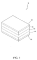
- Fig. 1 is a block diagram showing the secondary battery of the present invention
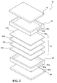
- Fig. 2 is an exploded diagram showing the secondary battery of the present invention
- Fig. 3 is a cross-sectional diagram showing the secondary battery of the present invention.
- the secondary battery 10 of the present invention mainly comprises an upper housing 101, an upper accommodated tank 105, a main component of the secondary battery 109, a lower accommodated tank 107, and a lower housing 103 that are laminated orderly by layers from top to bottom so as to form a closely connected structure of the secondary battery.
- the components of the present invention are made of a PCB material except the main component of the secondary battery 109, and the PCB material adopted can be, for example, FR4.
- the upper accommodated tank 105 and the lower accommodated tank 107 are used to accommodate an electrolyzed material 111; the main component of the secondary battery 109 is inserted between the upper accommodated tank 105 and the lower accommodated tank 107.
- the main component of the secondary battery 109, the upper accommodated tank 105 and the lower accommodated tank 107 can be laminated by pressing, adhering and so on, and then the upper housing 101 can cover and seal the upper accommodated tank 105, while the lower housing 103 can cover and seal the lower accommodated tank 107 as well as stack them by pressing, adhering and so on.
- the choices of the above mentioned electrolyzed material 111 depend on the main component of the secondary battery 109 used. For example, an electrolyte made of organic solvents or nonaqueous solvents can be used, or an electrolyzed-like material that can be sprayed or coated can be use so as to replace the electrolyte.
- the above-mentioned upper accommodated tank 105 and the lower accommodated tank 107 further provide at least one ventilated hole 105a, 107a on their walls respectively in order to exhaust the reacted gas.
- the specific method to stack the main component of the secondary battery 109, the upper accommodated tank 105 and the lower accommodated tank 107, the specific method to cover and seal the upper accommodated tank 105 by the upper housing 101, and the specific method to cover and seal the lower accommodated tank 107 by the lower housing 103 can be carried out by using epoxy resin as the adhering medium, and then to stack the main component of the secondary battery 109, the upper accommodated tank 105 and the lower accommodated tank 107, to cover and seal the upper accommodated tank 105 by the upper housing 101, and to cover and seal the lower accommodated tank 107 by the lower housing 103 by printing, coating or film laminating, and then to press them in the hot-press machine under temperature of 40 ⁇ 120 and pressure of 2 ⁇ 50 kg/cm 2 .
- the main component of the secondary battery 109 in accordance with the present invention mainly comprises an anode 109a, a cathode 109c and separators 109b and 109d, wherein the separators 109b and 109d are mainly used to separate the anode 109a and the cathode 109c.
- the main component of the secondary battery 109 of the present invention can use the same materials adopted by the present lithium rechargeable battery, Ni-H rechargeable battery and lithium polymer rechargeable battery. Certainly, the present invention is not limited to the materials used to manufacture lithium rechargeable battery, Ni-H rechargeable battery and lithium polymer rechargeable battery. Those skilled in the art can use any other materials for the main component of the secondary battery 109, and these changes are still protected within the scope of the present invention.
- Fig. 4 is a block diagram showing the secondary battery providing an upper and a lower leak-proof layers therein in accordance with the present invention
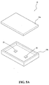
- fig. 5A is an exploded diagram showing the upper leak-proof layer of the present invention
- fig. 5B is an exploded diagram showing the lower leak-proof layer of the present invention.
- the present invention provides an upper leak-proof layer 21 and a lower leak-proof layer 23 on the upper outer side and the lower outer side of the secondary battery 10 respectively, and the two layers 21, 23 are similarly laminating by layers and closely connect to the upper and lower sides of the secondary battery 10 respectively In fig.
- the upper leak-proof layer 21 comprises an upper slot 21b and an upper cover 21 a; the upper cover 21 a is used to cover and seal the upper slot 21 b.
- the lower leak-proof layer 23 comprises a lower slot 23b and a lower cover 23a; the lower cover 23a is used to cover and seal the upper slot 23b.
- the upper slot 21b, the lower slot 23b, the upper cover 21a and the lower cover 23a of this embodiment are also made of a PCB material.
- the upper slot 21b can hold and accommodate the electrolyzed material 111 leaked out from the upper accommodated tank 105
- the lower slot 23b can hold and accommodate the electrolyzed material 111 leaked out from the lower accommodated tank 107.
- Fig. 6A is an exploded diagram showing the upper leak-proof layer of another embodiment of the present invention
- fig. 6B is an exploded diagram showing the lower leak-proof layer of another embodiment of the present invention.
- the upper leak-proof layer 21 comprises an upper absorber 21c and an upper cover 21 a; the upper cover 21a is used to cover and seal the upper absorber 21c.
- the lower leak-proof layer 23 comprises a lower absorber 23c and a lower cover 23a; the lower cover 23a is used to cover and seal the lower absorber 23c.
- the upper cover 21a and the lower cover 23a of this embodiment are also made of a PCB material, and the upper absorber 21c and the lower absorber 23c are made of an absorbable material.
- the upper absorber 2 1 c can be used to absorb and hold the electrolyzed material 111 leaked out from the upper accommodated tank 105, while the lower absorber 23c can used to absorb and hold the electrolyzed material 111 leaked out from the lower accommodated tank 107.
- the specific structure adopted by the upper accommodated tank 105, the lower accommodated tank 107, the upper slot 21b and the lower slot 23b of the present invention mentioned above can be a hollow frame structure such as a hollow rectangular frame in order to accommodate an electrolyzed material 111 by a closed and enveloped internal space therein.
- sensors 25 are provided to the upper slot 21b, the lower slot 23b, the upper absorber 21c and the lower absorber 23c, respectively. The electric signals are produced as the sensors 25 detect the electrolyzed materials 111 so as to notify on the leakage of electrolyzed materials 111.
- Fig. 7 is a block diagram showing the secondary battery providing a metal sheet therein in accordance with the present invention
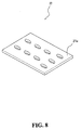
- fig. 8 is a structure diagram showing the metal sheet of the present invention.
- a metal sheet 27 is connected closely and laminated to the outer side of the upper and lower covers 21a, 23a according to the present invention. Numerous holes 27a are provided to the metal sheet 27 to facilitate the dissipation of heat produced inside the secondary battery 10, while the safety of use of the secondary battery 10 of the present invention can be improved by the firmness of its physical nature.
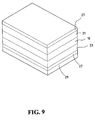
- Fig. 9 is a block diagram showing the secondary battery providing a circuit-control layer therein in accordance with the present invention
- fig. 10 is a structure diagram showing the circuit-control layer of the present invention.
- the secondary battery 10 of the present invention further comprises a circuit-control layer 29 which can be connected closely and laminated to the outer side of the metal sheet 27.
- the circuit-control layer 29 includes a printed circuit board substrate 29a and at least one electric components 29b. These electric components 29b are directly soldered on the printed circuit substrate 29a.
- the circuit formed by these circuit components 29b can be rechargeable circuits, electric power management circuits and so on, and the printed circuit substrate 29a can be made of a CCL (copper clad laminate)-based PCB material.
- Fig. 11 is a block diagram showing the secondary battery providing via holes therein in accordance with the present invention.
- each layer 10, 21, 23, 27, 29 of the present invention are provided with via holes 31 respectively, and these via holes 31 of each layer are able to connect to each other.
- via holes can be connected in a straight line.
- the via holes 31 provided to the outer most layer, such as via holes 31 of the circuit-control layer 29, are connected further to a pad (not shown) and then connected to outside through the pad in order to enable the main component of the secondary battery 109 within the layers to be electrically connected to outside as well as to give consideration to safety so as to prevent users from contacting the main component of the secondary battery directly.
- the secondary battery 10 of the present invention provides a structure of the secondary battery different from that of prior art. Meanwhile, because all components except the main components of the secondary battery 109 according to present invention are all made of a PCB material, the methods to laminate each component by layers to form a secondary battery 10 with a closely connected structure can also directly use a PCB- related processes.
Landscapes
- Chemical & Material Sciences (AREA)
- Chemical Kinetics & Catalysis (AREA)
- Electrochemistry (AREA)
- General Chemical & Material Sciences (AREA)
- Engineering & Computer Science (AREA)
- Manufacturing & Machinery (AREA)
- Inorganic Chemistry (AREA)
- Microelectronics & Electronic Packaging (AREA)
- Battery Mounting, Suspending (AREA)
- Secondary Cells (AREA)
- Sealing Battery Cases Or Jackets (AREA)
Applications Claiming Priority (2)
| Application Number | Priority Date | Filing Date | Title |
|---|---|---|---|
| CNB2004100455408A CN100336264C (zh) | 2004-05-28 | 2004-05-28 | 二次电池 |
| CN200410045540 | 2004-05-28 |
Publications (1)
| Publication Number | Publication Date |
|---|---|
| EP1601042A1 true EP1601042A1 (de) | 2005-11-30 |
Family
ID=34935565
Family Applications (1)
| Application Number | Title | Priority Date | Filing Date |
|---|---|---|---|
| EP05008801A Withdrawn EP1601042A1 (de) | 2004-05-28 | 2005-04-21 | Wiederaufladbare Batterie enthaltend Tanks aus einem Material für gedruckte Schaltungen |
Country Status (2)
| Country | Link |
|---|---|
| EP (1) | EP1601042A1 (de) |
| CN (1) | CN100336264C (de) |
Citations (5)
| Publication number | Priority date | Publication date | Assignee | Title |
|---|---|---|---|---|
| FR2588420A1 (fr) * | 1985-10-09 | 1987-04-10 | Kalfon Rene | Batterie d'accumulateur extraplate |
| US4830938A (en) * | 1985-06-04 | 1989-05-16 | The Dow Chemical Company | Secondary battery |
| JPH02121385A (ja) * | 1988-10-31 | 1990-05-09 | Brother Ind Ltd | 蓄電池内蔵型プリント配線板 |
| US5518836A (en) * | 1995-01-13 | 1996-05-21 | Mccullough; Francis P. | Flexible carbon fiber, carbon fiber electrode and secondary energy storage devices |
| WO1999030376A2 (en) * | 1997-12-05 | 1999-06-17 | Mi Rae Battery Co., Ltd. | Battery-included pcb |
Family Cites Families (2)
| Publication number | Priority date | Publication date | Assignee | Title |
|---|---|---|---|---|
| US5019468A (en) * | 1988-10-27 | 1991-05-28 | Brother Kogyo Kabushiki Kaisha | Sheet type storage battery and printed wiring board containing the same |
| JPH11274735A (ja) * | 1998-03-25 | 1999-10-08 | Toshiba Battery Co Ltd | 多層印刷配線板 |
-
2004
- 2004-05-28 CN CNB2004100455408A patent/CN100336264C/zh not_active Expired - Fee Related
-
2005
- 2005-04-21 EP EP05008801A patent/EP1601042A1/de not_active Withdrawn
Patent Citations (5)
| Publication number | Priority date | Publication date | Assignee | Title |
|---|---|---|---|---|
| US4830938A (en) * | 1985-06-04 | 1989-05-16 | The Dow Chemical Company | Secondary battery |
| FR2588420A1 (fr) * | 1985-10-09 | 1987-04-10 | Kalfon Rene | Batterie d'accumulateur extraplate |
| JPH02121385A (ja) * | 1988-10-31 | 1990-05-09 | Brother Ind Ltd | 蓄電池内蔵型プリント配線板 |
| US5518836A (en) * | 1995-01-13 | 1996-05-21 | Mccullough; Francis P. | Flexible carbon fiber, carbon fiber electrode and secondary energy storage devices |
| WO1999030376A2 (en) * | 1997-12-05 | 1999-06-17 | Mi Rae Battery Co., Ltd. | Battery-included pcb |
Non-Patent Citations (1)
| Title |
|---|
| PATENT ABSTRACTS OF JAPAN vol. 014, no. 348 (E - 0957) 27 July 1990 (1990-07-27) * |
Also Published As
| Publication number | Publication date |
|---|---|
| CN100336264C (zh) | 2007-09-05 |
| CN1705154A (zh) | 2005-12-07 |
Similar Documents
| Publication | Publication Date | Title |
|---|---|---|
| TWI591875B (zh) | 用於薄膜電池之電芯 | |
| CN102144315B (zh) | 薄膜电池 | |
| US8420255B2 (en) | Storage cell and method of manufacturing same | |
| US7329473B2 (en) | Secondary battery | |
| US20060267546A1 (en) | Secondary battery, and secondary battery matrix and multi-lamination secondary battery matrix having the same | |
| CN101436692B (zh) | 可充电电池 | |
| CN101494300A (zh) | 电池组 | |
| JP5366220B2 (ja) | 浸水ラベルを含む二次電池 | |
| KR101735511B1 (ko) | 패턴화된 형상을 갖는 배터리 셀 및 그 제조방법 | |
| WO2013100493A1 (ko) | 표면 실장형 슈퍼 커패시터 | |
| EP1601042A1 (de) | Wiederaufladbare Batterie enthaltend Tanks aus einem Material für gedruckte Schaltungen | |
| JP7596018B2 (ja) | フレキシブルプリント回路基板を含むパウチ型電池セル | |
| EP1615287A1 (de) | Wiederaufladbare Batterie, eine Matrix und eine mehrfach laminierte Matrix aus wiederaufladbaren Batterien, welche diese Batterie umfassen | |
| KR20120085540A (ko) | 2차 전지 | |
| KR100561293B1 (ko) | 이차전지 | |
| KR100737927B1 (ko) | 재충전지 제조 방법 | |
| CN222581445U (zh) | 电池、充放电模组及电子设备 | |
| CN223514077U (zh) | 电池壳体结构及电池 | |
| US20070015051A1 (en) | Secondary battery | |
| WO2013080685A1 (ja) | 電池モジュール | |
| KR102911160B1 (ko) | 이차 전지용 파우치 및 이를 포함하는 이차 전지 | |
| EP1655794A2 (de) | Doppel-Elektrodenplatte mit elektrischem Schaltungsanordnungschichtlaminat und damit ausgerüsteter wiederaufladbarer Batterie | |
| US20070082233A1 (en) | Double-electrode plate with electrical circuitry layer laminate and the secondary battery with the same | |
| KR100735121B1 (ko) | 이차전지, 이차전지 매트릭스 및 멀티 라미네이션 이차전지매트릭스 | |
| KR100735120B1 (ko) | 전기 회로소자층 라미네이트를 구비하는 이중 전극플레이트 및 이를 구비하는 이차전지 |
Legal Events
| Date | Code | Title | Description |
|---|---|---|---|
| PUAI | Public reference made under article 153(3) epc to a published international application that has entered the european phase |
Free format text: ORIGINAL CODE: 0009012 |
|
| AK | Designated contracting states |
Kind code of ref document: A1 Designated state(s): AT BE BG CH CY CZ DE DK EE ES FI FR GB GR HU IE IS IT LI LT LU MC NL PL PT RO SE SI SK TR |
|
| AX | Request for extension of the european patent |
Extension state: AL BA HR LV MK YU |
|
| 17P | Request for examination filed |
Effective date: 20060530 |
|
| AKX | Designation fees paid |
Designated state(s): DE FR GB |
|
| 17Q | First examination report despatched |
Effective date: 20070216 |
|
| STAA | Information on the status of an ep patent application or granted ep patent |
Free format text: STATUS: THE APPLICATION IS DEEMED TO BE WITHDRAWN |
|
| 18D | Application deemed to be withdrawn |
Effective date: 20080812 |