EP1601072B1 - Système et module de mise en forme des faisceaux optiques pour montage des lasers à diodes - Google Patents
Système et module de mise en forme des faisceaux optiques pour montage des lasers à diodes Download PDFInfo
- Publication number
- EP1601072B1 EP1601072B1 EP04012863A EP04012863A EP1601072B1 EP 1601072 B1 EP1601072 B1 EP 1601072B1 EP 04012863 A EP04012863 A EP 04012863A EP 04012863 A EP04012863 A EP 04012863A EP 1601072 B1 EP1601072 B1 EP 1601072B1
- Authority
- EP
- European Patent Office
- Prior art keywords
- lateral displacement
- laser beams
- shaping optical
- laser
- optical unit
- Prior art date
- Legal status (The legal status is an assumption and is not a legal conclusion. Google has not performed a legal analysis and makes no representation as to the accuracy of the status listed.)
- Expired - Lifetime
Links
- 238000007493 shaping process Methods 0.000 title claims description 38
- 238000006073 displacement reaction Methods 0.000 claims abstract description 29
- 230000003287 optical effect Effects 0.000 claims description 45
- 238000011144 upstream manufacturing Methods 0.000 claims description 3
- 230000005855 radiation Effects 0.000 description 13
- 238000001816 cooling Methods 0.000 description 4
- 230000008878 coupling Effects 0.000 description 3
- 238000010168 coupling process Methods 0.000 description 3
- 238000005859 coupling reaction Methods 0.000 description 3
- 230000035945 sensitivity Effects 0.000 description 3
- 230000005540 biological transmission Effects 0.000 description 2
- 238000000576 coating method Methods 0.000 description 2
- 229910000679 solder Inorganic materials 0.000 description 2
- 230000003667 anti-reflective effect Effects 0.000 description 1
- 238000003491 array Methods 0.000 description 1
- 239000011248 coating agent Substances 0.000 description 1
- 239000013078 crystal Substances 0.000 description 1
- 230000000694 effects Effects 0.000 description 1
- 230000002349 favourable effect Effects 0.000 description 1
- 239000011521 glass Substances 0.000 description 1
- 238000003384 imaging method Methods 0.000 description 1
- 238000003780 insertion Methods 0.000 description 1
- 230000037431 insertion Effects 0.000 description 1
- 239000000463 material Substances 0.000 description 1
- 230000010287 polarization Effects 0.000 description 1
- 238000005086 pumping Methods 0.000 description 1
- 238000007789 sealing Methods 0.000 description 1
- 238000004904 shortening Methods 0.000 description 1
- 230000007704 transition Effects 0.000 description 1
Images


Classifications
-
- G—PHYSICS
- G02—OPTICS
- G02B—OPTICAL ELEMENTS, SYSTEMS OR APPARATUS
- G02B19/00—Condensers, e.g. light collectors or similar non-imaging optics
- G02B19/0033—Condensers, e.g. light collectors or similar non-imaging optics characterised by the use
- G02B19/0047—Condensers, e.g. light collectors or similar non-imaging optics characterised by the use for use with a light source
- G02B19/0052—Condensers, e.g. light collectors or similar non-imaging optics characterised by the use for use with a light source the light source comprising a laser diode
- G02B19/0057—Condensers, e.g. light collectors or similar non-imaging optics characterised by the use for use with a light source the light source comprising a laser diode in the form of a laser diode array, e.g. laser diode bar
-
- G—PHYSICS
- G02—OPTICS
- G02B—OPTICAL ELEMENTS, SYSTEMS OR APPARATUS
- G02B19/00—Condensers, e.g. light collectors or similar non-imaging optics
- G02B19/0004—Condensers, e.g. light collectors or similar non-imaging optics characterised by the optical means employed
- G02B19/0028—Condensers, e.g. light collectors or similar non-imaging optics characterised by the optical means employed refractive and reflective surfaces, e.g. non-imaging catadioptric systems
-
- G—PHYSICS
- G02—OPTICS
- G02B—OPTICAL ELEMENTS, SYSTEMS OR APPARATUS
- G02B27/00—Optical systems or apparatus not provided for by any of the groups G02B1/00 - G02B26/00, G02B30/00
- G02B27/09—Beam shaping, e.g. changing the cross-sectional area, not otherwise provided for
- G02B27/0938—Using specific optical elements
- G02B27/095—Refractive optical elements
- G02B27/0972—Prisms
-
- H—ELECTRICITY
- H01—ELECTRIC ELEMENTS
- H01S—DEVICES USING THE PROCESS OF LIGHT AMPLIFICATION BY STIMULATED EMISSION OF RADIATION [LASER] TO AMPLIFY OR GENERATE LIGHT; DEVICES USING STIMULATED EMISSION OF ELECTROMAGNETIC RADIATION IN WAVE RANGES OTHER THAN OPTICAL
- H01S5/00—Semiconductor lasers
- H01S5/40—Arrangement of two or more semiconductor lasers, not provided for in groups H01S5/02 - H01S5/30
- H01S5/4012—Beam combining, e.g. by the use of fibres, gratings, polarisers, prisms
-
- H—ELECTRICITY
- H01—ELECTRIC ELEMENTS
- H01S—DEVICES USING THE PROCESS OF LIGHT AMPLIFICATION BY STIMULATED EMISSION OF RADIATION [LASER] TO AMPLIFY OR GENERATE LIGHT; DEVICES USING STIMULATED EMISSION OF ELECTROMAGNETIC RADIATION IN WAVE RANGES OTHER THAN OPTICAL
- H01S5/00—Semiconductor lasers
- H01S5/40—Arrangement of two or more semiconductor lasers, not provided for in groups H01S5/02 - H01S5/30
- H01S5/4025—Array arrangements, e.g. constituted by discrete laser diodes or laser bar
Definitions
- the present invention relates to beam shaping optics for a diode laser array.
- a pump light source for diode-pumped high-power solid-state lasers for example active with Mikrokanalssensenken cooled diode laser arrays with vertical laser diode stacks (vertical stacks) of laser diode bars are used. With a sufficiently large stack height (about 50 laser diode bars), these stacks have an approximately equally large beam parameter product in the horizontal direction (slow axis, SA) and in the vertical direction (fast axis, FA). This allows a simple coupling the emanating from these vertical stacks of radiation in a (nearly) rotationally symmetrical light mixer with approximately maintaining the brilliance of the pump radiation. In the light mixer, the pump radiation is homogenized by multiple reflection. The radiation emerging from the light mixer is suitable for imaging a round pump leak on a laser crystal. The disadvantage is the limited life expectancy of the actively cooled, vertical stacks of about 10,000 h.
- a disadvantage is the optical format, which results from laser diode bars arranged side by side in the SA direction.
- the asymmetry of the beam quality in the horizontal stack is further increased by the adjacent bars and the resulting broadening of the total cross section of the emitted radiation along the SA direction.
- FA collimator lenses with unusually long focal length are required for optically flush stacking in the FA direction.
- the low divergence of the beams thus collimated requires a very high accuracy of the optical components in the further beam path.
- the overall height for practical applications is too great for the number of stacked horizontal stacks required for symmetrical beam quality. Therefore, to achieve approximate symmetry of the output radiation of horizontal stacks, beam shaping optics are necessary.
- DE 199 39 750 A1 discloses a beam-shaping optical system for combining three laser beams, which are supplied by three diode bars lying in a common horizontal plane, to form a superimposed laser beam. With this optical arrangement, a reduction of the extent of the laser radiation in the SA direction is achieved. In the beam path immediately after the diode bars is a correction optics for beam collimation both in the FA direction and in the SA direction.
- the optical arrangement has lateral displacement elements for lateral displacement (parallel displacement) of the two outer laser beams along the SA direction, which consist of a beam deflection element and a coupling element (prism cube).
- DE 199 39 750 A1 further discloses a beam-shaping optical system for combining two laser beams, which are provided in the SA direction next to one another, in the FA direction slightly staggered relative to each other diode bars, to a combed laser beam.
- This optical arrangement comprises two plane-parallel plates arranged in the FA direction one above the other and in the SA direction at an angle to the incoming radiation, which are passed through in transmission.
- the two incoming laser beams are offset laterally in the SA direction by half the center distance of the beams, whereby they are pushed one above the other like a comb (so-called interleaving):
- a beam-forming optical system with at least one Verkarmmungsshake for bringing together three laterally offset in two directions, incoming laser beams to a discontinuous intermeshed laser beam, wherein the Verkymmungsscribe two Lateralversetzsakuen for Lateralver(7) each one of the two in the first direction outer incoming laser beams along the first direction to the central incoming laser beam, which passes laterally unassembled through the meshing stage, and wherein the lateral displacement units each comprise at least one lateral displacement element of higher refractive index than the medium located in the beam path of the middle laser beam in the meshing step, the one of the outer laser beams in the lateral displacement elements traveled path length is selected such that at the end of the Verklammungslose the diameter of the laser beams at least in the first direction are approximately equal and the outgoing, intermeshed laser beam has a substantially identical divergence behavior over its beam cross-section.
- the incoming laser beams may e.g. are supplied by a known from DE 100 61 265 A1 horizontal stack, wherein each one laser beam is emitted from a diode bar and the diode bars in the first horizontal direction (SA) are arranged side by side and wherein the diode bars in the vertical direction slightly staggered to each other are. Since typically more than three diode bars are arranged side by side on a horizontal stack, it may be favorable to arrange a plurality of concealment devices side by side or one behind the other in the beam path of the laser beams.
- the beam-shaping optical system in contrast to the prior art, by means of the beam-shaping optical system according to the invention, three incoming laser beams can be intermingled, for which only two lateral displacement units are required.
- the geometric path length of the two outer laser beams through the meshing stage is greater than the geometric path length traveled by the average laser beam in the meshing stage due to the lateral offset.
- Laser beams having beam divergence expand depending on the traversed geometric path length.
- the diameter of the three laser beams at the end of the meshing step is made approximately equal by suitable design of the refractive index of the lateral displacement elements and the path length of the outer laser beams through the lateral displacement elements, so as to ensure that the outgoing, intermeshed laser beam has a substantially identical divergence behavior over its beam cross section having.
- the combed beams can be focused by other optical elements (for example, lenses or lens telescopes) in a light mixer or directly on a solid-state laser medium.
- the beam expansion within an optical medium is lower in a higher-refractive medium than in a lower-refractive medium, which results from the fact that the light rays are refracted by the transition into the higher-refractive medium to the optical axis and therefore in the optical medium with less divergence.
- each of the lateral displacement units has a lateral displacement element of higher refractive index than the medium which is in the beam path of the middle laser beam in the meshing step.
- the incoming laser beams and the outgoing laser beam are parallel to one another, which enables a compact design of the beam-shaping optical system and minimizes the adjustment sensitivity.
- the middle beam preferably passes completely through the beam shaping optics in air, so that it passes through the beam shaping optics without being influenced by an optical element. This minimizes the cost and adjustment sensitivity of the beamforming optics and the radiation intensity losses.
- the lateral displacement units generate the lateral offset by total reflection on at least two total reflection surfaces.
- beam deflection by total reflection occurs only small loss of light and total reflection surfaces need not be anti-reflective.
- the Lateralversetzsakuen are designed as Doppelumlenkprismen.
- the total reflection on two side surfaces of double deflection prisms is a particularly simple way to produce a lateral offset with a single optical element. By combining the two reflection surfaces in one component, the adjustment effort and the risk of misalignment are minimized.
- a further intermeshing stage is arranged in front of the intermeshing stage, which merges two incoming laser beams laterally offset in the first and second directions into a combed outgoing laser beam.
- the upstream skimming step may comprise two lateral displacement units, in particular plane parallel plates, for laterally displacing the two incoming laser beams along the first direction towards each other.
- the intersection can be optimized.
- Flat plates are inexpensive to produce optical elements, which can be achieved easily Lateralver algebra.
- the incoming laser beam enters an entrance surface of the Lateralversetzsaku at the Brewster angle, whereby even without reflection-reducing coatings unwanted reflections at the entrance surface (and at the exit surface) are avoided.
- the invention also relates to a beam-shaping module having at least two beam-shaping optical systems of the type described above, which are joined together along at least one stacking unit along the second direction.
- the individual beam-shaping optics are identical.
- the beam-shaping module can be advantageously used to combine laser beams delivered by two or more horizontal stacks stacked along the second vertical direction (FA).
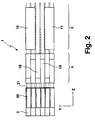
- the beam-shaping optical system 1 shown in a plan view in FIG. 1 in a plan view and in FIG. 2 serves to bring together (conceal) six laser beams which are parallel to one another in Z.sub.1 of a diode laser arrangement 2 which is formed as a horizontal stack with six diode bars 30 Direction are emitted and four of which are shown in Fig. 1 by their marginal rays.
- the diode bars 30 are arranged with a small vertical offset (so-called "bar pitch").
- This pitch is typically about 1.5 mm, which corresponds to about 1.5 to 2 times the extent of a laser beam 16, 17 in the Y direction (FA direction), after it has passed through an FA collimator 21 , which connects directly to the diode bars 30 .
- the heat sinks of the diode bars 30 are preferably made slightly wedge-shaped in the X direction (SA direction), which allows the use of identical heat sinks for all the diode bars 30 .
- SA direction X direction
- the radiation of the diode bars 30 is arranged in the form of a flat staircase. Relative to the horizontally oriented SA-direction a non-illustrated cooling plate of the horizontal stack 2 is slightly tilted.
- the beam-shaping optical system 1 for combining the laser radiation of the diode bars 30 has two intermeshing stages 3, 4 arranged one behind the other in the beam path.
- the laser beams 16, 17 emitted by two neighboring diode bars 30 of the horizontal stack 2 are superposed in pairs symmetrically in pairs by means of two lateral displacement units 18, 19 which are formed by two plane parallel plates arranged at opposite equal angles to the beam direction. Due to the symmetry of the arrangement, the optical path length for the laser beams from the diode bars 30 in the first interlacing stage 4 is the same.
- the plane-parallel plates 18, 19 are passed through in transmission.
- the surface normal of an entry face 20 of the plane parallel plates with the laser beams 16, 17 forms an angle which corresponds to the Brewster angle ⁇ B of the material of the plane parallel plates 18, 19 .
- the diode bars 30 emit horizontal polarization, an antireflection coating of the input and output surfaces of the plane-parallel plates 18, 19 is dispensed with.
- For a plane parallel plate 18, 19 only two optical surfaces, namely the entrance surface 20 and an exit surface 23, with good parallelism are needed.
- the adjustment sensitivity of the plane parallel plates 18, 19 is low.
- the direction of the exiting radiation is influenced neither by twisting nor by displacement of the plane parallel plates 18, 19 .
- the laser beams 5, 6, 7 arranged horizontally offset after the first slicing stage 4 are completely superimposed so that an outgoing laser beam 8 leaves the beam-shaping optical system 1 as a vertical optical laser beam stack.
- the second intermeshing stage 3 has two Lateralversetzsakuen 10, 11 in the form of Doppelumlenkprismen positioned with perpendicular to the beam propagation direction input and output surfaces and parallel obliquely arranged side surfaces 12, 13, 14, 15 for pairwise total reflection and thus to achieve a horizontal beam offset are.
- the vertical extent of the Doppelumlenkprismen 10, 11 is twice the ingot pitch.
- Verklammungstress 3 can be dispensed with a complete symmetry, since the effective path lengths of the three incoming laser beams 5, 6, 7th are almost the same length.
- the optical shortening by propagation of the two outer laser beams 5, 7 in the higher refractive index medium of the Doppelumlenkprismen 10, 11 is used here to compensate for the larger geometric path length of the two horizontally offset laser beams 5, 7 relative to the central laser beam 6 .
- only two identical Doppelumlenkprismen 10, 11 are required for the merger of the laser radiation of the horizontal stack 2 .
- the middle laser beam 6 without passing through an optical element , passes between the two double deflection prisms 10, 11 .
- the plane-parallel plates 18, 19 of the first intermeshing stage 4 can be fastened, for example, to the horizontal stack 2 .
- the cooling plates and / or the heat sinks of the horizontal stack 2 must be extended sufficiently far below the plane-parallel plates 18, 19 and preferably comprise a plane, SA-parallel bearing surface onto which the plane parallel plates 18, 19 can be glued.
- the outgoing laser beam 8 is focused in the FA direction with the aid of a cylindrical lens (not shown) onto the entrance surface of a light mixer, not shown, and imaged in the SA direction with the aid of a cylindrical lens telescope on this entrance surface.
- FIG. 3 shows a side view of a beam-shaping module 100 with two of the beam-shaping optical systems 1 shown in FIG. 1, which are constructed identically and stacked one above the other in the Y-direction to form a stacking unit 101 .
- the Doppelumlenkprismen 10, 11 of the second Verkarmmungstress 3 can in this case, for example, with the help of additional - located outside the beam path - spacers 22 - preferably made of glass - assembled into a quasi-monolithic stack (eg glued).
- FIG. 4 illustrates the reduction in the divergence of a laser beam as it passes through a plane plate 42 which has a higher refractive index than the surrounding medium (eg air).
- the laser beam Before entering the plane plate 42, the laser beam has a diameter S 1 in the X direction. It is illustrated by two marginal rays 40, 41 , which impinge on an entry surface 43 of the plane plate 42 at an angle ⁇ 1 with respect to the incidence solder (Z direction).
- the marginal rays 40, 41 When passing through the entrance surface, the marginal rays 40, 41 are refracted towards the insertion slot so that they run in the interior of the plane plate 42 at an angle ⁇ 2 with respect to the solder.
- the opening angle of the laser beam and thus the beam divergence is therefore within the plane plate 42 with a larger refractive index thus lower than in the surrounding medium with a lower refractive index.
- the Ranstrahlen 40, 41 through an exit surface 44 of the plane plate 42 these are broken so that they again behind the plane plate 42 at the angle ⁇ 1 with respect to the Z-direction.
- the beam divergence before the entry of the laser beam into the plane plate 42 and after the exit of the laser beam from the plane plate 42 are thus identical.
- the diameter S 2 of the laser beam after emerging from the plane plate 42 in the X direction is lower by 2 ⁇ s than that of a laser beam which propagates exclusively in the medium with the lower refractive index.
- the marginal rays 45, 46 of such a laser beam are shown in dashed lines in Fig. 4.
Landscapes
- Physics & Mathematics (AREA)
- General Physics & Mathematics (AREA)
- Optics & Photonics (AREA)
- Semiconductor Lasers (AREA)
- Optical Head (AREA)
- Optical Couplings Of Light Guides (AREA)
Claims (10)
- Optique de mise en forme de faisceau (1) comprenant au moins un étage d'entrelacement (3) pour la réunion de trois faisceaux laser entrants (5, 6, 7) décalés latéralement les uns par rapport aux autres dans deux directions (X, Y) en un faisceau laser sortant entrelacé (8), l'étage d'entrelacement (3) présentant deux unités de décalage latéral (10, 11) pour le décalage latéral respectif d'un des deux faisceaux laser entrants extérieurs (5, 7) dans la première direction (X) le long de la première direction (X) vers le faisceau laser entrant central (6), lequel traverse l'étage d'entrelacement (3) sans être décalé latéralement, et les unités de décalage latéral (10, 11) présentant chacune au moins un élément de décalage latéral ayant un indice de réfraction supérieur à celui du milieu qui se trouve dans le trajet des rayons du faisceau laser central (6) dans l'étage d'entrelacement (3), la longueur de parcours effectuée par les faisceaux laser extérieurs (5, 7) dans les éléments de décalage latéral étant choisie de telle manière qu'à l'extrémité de l'étage d'entrelacement (3) le diamètre des faisceaux laser (5, 6, 7) soit à peu près égal au moins dans la première direction (X) et que le faisceau laser entrelacé (8) présente un comportement de divergence essentiellement identique sur sa section de faisceau.
- Optique de mise en forme de faisceau selon la revendication 1, caractérisée par le fait que les faisceaux laser entrants (5, 6, 7) et le faisceau laser sortant (8) sont parallèles entre eux.
- Optique de mise en forme de faisceau selon la revendication 1 ou 2, caractérisée par le fait que le faisceau laser central (6) se propage dans l'air.
- Optique de mise en forme de faisceau selon l'une des revendications précédentes, caractérisée par le fait que les unités de décalage latéral (10, 11) produisent le décalage latéral chacune par réflexion totale sur au moins deux surfaces de réflexion totale (12, 13, 14, 15).
- Optique de mise en forme de faisceau selon la revendication 4, caractérisée par le fait que les unités de décalage latéral (10, 11) sont réalisées sous la forme de doubles prismes déviateurs.
- Optique de mise en forme de faisceau selon l'une des revendications précédentes, caractérisée par le fait qu'avant l'étage d'entrelacement (3) se trouve un autre étage d'entrelacement (4) qui réunit deux faisceaux laser entrants (16, 17) décalés latéralement l'un par rapport à l'autre dans la première et la deuxième direction (X, Y) en un faisceau laser sortant entrelacé (6).
- Optique de mise en forme de faisceau selon la revendication 6, caractérisée par le fait que l'étage d'entrelacement (4) placé en amont comprend chaque fois deux unités de décalage latéral (18, 19), en particulier des lames à faces parallèles, pour le décalage latéral des deux faisceaux laser entrants (16, 17) l'un vers l'autre le long de la première direction (X).
- Optique de mise en forme de faisceau selon la revendication 7, caractérisée par le fait que le faisceau laser entrant (16, 17) arrive sur une surface d'entrée (20) de l'unité de décalage latéral (18, 19) sous un angle de Brewster (αB).
- Module de mise en forme de faisceau (100) comprenant au moins deux optiques de mise en forme de faisceau (1), selon l'une des revendications précédentes, qui sont réunies en au moins une unité d'empilage (101) le long de la deuxième direction (Y).
- Module de mise en forme de faisceau selon la revendication 9, caractérisé par le fait que les optiques de mise en forme de faisceau (1) sont identiques.
Priority Applications (4)
| Application Number | Priority Date | Filing Date | Title |
|---|---|---|---|
| EP04012863A EP1601072B1 (fr) | 2004-05-29 | 2004-05-29 | Système et module de mise en forme des faisceaux optiques pour montage des lasers à diodes |
| DE502004003956T DE502004003956D1 (de) | 2004-05-29 | 2004-05-29 | Strahlformungsoptik und -modul für eine Diodenlaseranordnung |
| AT04012863T ATE363758T1 (de) | 2004-05-29 | 2004-05-29 | Strahlformungsoptik und -modul für eine diodenlaseranordnung |
| US11/138,900 US7167312B2 (en) | 2004-05-29 | 2005-05-27 | Beam shaping optics and module for a diode laser arrangement |
Applications Claiming Priority (1)
| Application Number | Priority Date | Filing Date | Title |
|---|---|---|---|
| EP04012863A EP1601072B1 (fr) | 2004-05-29 | 2004-05-29 | Système et module de mise en forme des faisceaux optiques pour montage des lasers à diodes |
Publications (2)
| Publication Number | Publication Date |
|---|---|
| EP1601072A1 EP1601072A1 (fr) | 2005-11-30 |
| EP1601072B1 true EP1601072B1 (fr) | 2007-05-30 |
Family
ID=34925196
Family Applications (1)
| Application Number | Title | Priority Date | Filing Date |
|---|---|---|---|
| EP04012863A Expired - Lifetime EP1601072B1 (fr) | 2004-05-29 | 2004-05-29 | Système et module de mise en forme des faisceaux optiques pour montage des lasers à diodes |
Country Status (4)
| Country | Link |
|---|---|
| US (1) | US7167312B2 (fr) |
| EP (1) | EP1601072B1 (fr) |
| AT (1) | ATE363758T1 (fr) |
| DE (1) | DE502004003956D1 (fr) |
Families Citing this family (12)
| Publication number | Priority date | Publication date | Assignee | Title |
|---|---|---|---|---|
| JP4234697B2 (ja) * | 2005-06-15 | 2009-03-04 | 浜松ホトニクス株式会社 | レーザ装置 |
| US7265906B2 (en) * | 2005-07-12 | 2007-09-04 | The Boeing Company | Tri-to-hex light mixing and homogenizing apparatus and method |
| US7414793B2 (en) | 2006-07-21 | 2008-08-19 | The Boeing Company | White light splitting and homogenizing systems and methods |
| US7443591B1 (en) * | 2007-02-01 | 2008-10-28 | The Boeing Company | Homogenizing optical beam combiner |
| US7603017B2 (en) * | 2007-02-01 | 2009-10-13 | The Boeing Company | Multi-color curved multi-light generating apparatus |
| US7386214B1 (en) | 2007-02-01 | 2008-06-10 | The Boeing Company | Homogenizing optical beam combiner |
| DE102011016253B4 (de) | 2011-04-06 | 2014-02-27 | Laserline Gesellschaft für Entwicklung und Vertrieb von Diodenlasern mbH | Diodenlaser |
| US9690107B2 (en) | 2013-03-15 | 2017-06-27 | Trumpf Laser Gmbh | Device for wavelength combining of laser beams |
| US9851570B2 (en) | 2014-09-18 | 2017-12-26 | Ipg Photonics Corporation | Beam shaping of high intensity high frequency optical output |
| JP6704920B2 (ja) * | 2015-10-14 | 2020-06-03 | アルプスアルパイン株式会社 | 流路構造体および測定対象液体の測定装置 |
| JP2022108081A (ja) * | 2021-01-12 | 2022-07-25 | 三菱電機株式会社 | レーザモジュール |
| US11876343B2 (en) * | 2021-05-18 | 2024-01-16 | Trumpf Photonics, Inc. | Laser diode packaging platforms |
Family Cites Families (13)
| Publication number | Priority date | Publication date | Assignee | Title |
|---|---|---|---|---|
| US6873639B2 (en) * | 1993-05-28 | 2005-03-29 | Tong Zhang | Multipass geometry and constructions for diode-pumped solid-state lasers and fiber lasers, and for optical amplifier and detector |
| US6373868B1 (en) * | 1993-05-28 | 2002-04-16 | Tong Zhang | Single-mode operation and frequency conversions for diode-pumped solid-state lasers |
| DE4438368C3 (de) * | 1994-10-27 | 2003-12-04 | Fraunhofer Ges Forschung | Anordnung zur Führung und Formung von Strahlen eines geradlinigen Laserdiodenarrays |
| DE19514626C2 (de) * | 1995-04-26 | 1997-03-06 | Fraunhofer Ges Forschung | Anordnung zur Formung des geometrischen Querschnitts eines Strahlungsfeldes eines oder mehrerer Festkörper- und/oder Halbleiterlaser(s) |
| US6028722A (en) * | 1996-03-08 | 2000-02-22 | Sdl, Inc. | Optical beam reconfiguring device and optical handling system for device utilization |
| US5761234A (en) * | 1996-07-09 | 1998-06-02 | Sdl, Inc. | High power, reliable optical fiber pumping system with high redundancy for use in lightwave communication systems |
| US5784203A (en) * | 1996-11-26 | 1998-07-21 | Beckmann; Leo H. J. F. | Method and apparatus for combining the radiation output from a linear array of radiation sources |
| US5900981A (en) * | 1997-04-15 | 1999-05-04 | Scitex Corporation Ltd. | Optical system for illuminating a spatial light modulator |
| DE19918444C2 (de) * | 2000-03-15 | 2001-06-21 | Laserline Ges Fuer Entwicklung | Laseroptik sowie Diodenlaser |
| DE19939750C2 (de) * | 1999-08-21 | 2001-08-23 | Laserline Ges Fuer Entwicklung | Optische Anordnung zur Verwendung bei einer Laserdiodenanordnung sowie Laserdiodenanordnung mit einer solchen optischen Anordnung |
| US6377410B1 (en) * | 1999-10-01 | 2002-04-23 | Apollo Instruments, Inc. | Optical coupling system for a high-power diode-pumped solid state laser |
| DE10061265A1 (de) | 2000-12-06 | 2002-06-27 | Jenoptik Jena Gmbh | Diodenlaseranordnung |
| DE10204796A1 (de) * | 2002-02-01 | 2003-08-21 | Ozygus Bernd | Lasergainmodul |
-
2004
- 2004-05-29 EP EP04012863A patent/EP1601072B1/fr not_active Expired - Lifetime
- 2004-05-29 AT AT04012863T patent/ATE363758T1/de not_active IP Right Cessation
- 2004-05-29 DE DE502004003956T patent/DE502004003956D1/de not_active Expired - Lifetime
-
2005
- 2005-05-27 US US11/138,900 patent/US7167312B2/en not_active Expired - Lifetime
Also Published As
| Publication number | Publication date |
|---|---|
| EP1601072A1 (fr) | 2005-11-30 |
| US20050270652A1 (en) | 2005-12-08 |
| ATE363758T1 (de) | 2007-06-15 |
| US7167312B2 (en) | 2007-01-23 |
| DE502004003956D1 (de) | 2007-07-12 |
Similar Documents
| Publication | Publication Date | Title |
|---|---|---|
| DE112017000432B4 (de) | Prismen zur verbesserung der strahlqualität und bandbreitenverminderung nutzende wellenlängenstrahlkombinationslasersysteme | |
| DE19537265C1 (de) | Anordnung zur Zusammenführung und Formung der Strahlung mehrerer Laserdiodenzeilen | |
| DE19743322B4 (de) | Laserstrahlformgebungssystem | |
| DE112013007759B3 (de) | Halbleiterlaservorrichtung | |
| EP0863588B1 (fr) | Optique pour laser et laser à diode | |
| EP0803075B1 (fr) | Systeme optique s'utilisant dans un systeme de diode laser | |
| DE19751716C2 (de) | Anordnung zur Formung und Führung von Strahlung | |
| DE10220378B4 (de) | Laserlichtquellenvorrichtung mit optischen Elementen zur Strahlkorrektur | |
| DE102004002221B3 (de) | Vorrichtung zur optischen Strahltransformation einer linearen Anordnung mehrerer Lichtquellen | |
| EP0735397A2 (fr) | Dispositif micro-optique pour transformer des faisceaux d'un arrangement de diodes laser et procédé de fabrication d'un tel dispositif | |
| DE112011100813T5 (de) | System und verfahren zur selektiven repositionier- und drehwellenlängenstrahlkombination | |
| WO1998019202A1 (fr) | Dispositif optique de symetrisation du faisceau de diodes laser | |
| EP2217961A1 (fr) | Dispositif de mise en forme de faisceau | |
| EP1601072B1 (fr) | Système et module de mise en forme des faisceaux optiques pour montage des lasers à diodes | |
| EP1145390A2 (fr) | Systeme d'amplification laser | |
| DE112019003882B4 (de) | Lasersystem mit treppenförmig angeordneten slow-axis-kollimatoren | |
| DE112020000301T5 (de) | Systeme und verfahren zur ausrichtung von wellenlängenstrahlkombinierenden resonatoren | |
| EP2240984B1 (fr) | Structure laser à diodes destinée à la production de faisceaux laser ayant un produit de paramètres de faisceau optimisé quant au couplage de fibres | |
| EP2508934B1 (fr) | Laser à diodes | |
| EP2309309A2 (fr) | Dispositif destiné à la formation de rayons laser | |
| DE19752416A1 (de) | Verfahren und Vorrichtung zum Kombinieren der Strahlungsleistung einer linearen Anordnung von Strahlenquellen | |
| EP0903823B1 (fr) | Elément laser comprenant un réseau de lasers et méthode de fabrication | |
| EP1384105B1 (fr) | Dispositif de modelage de faisceau permettant le modelage de la section d'un faisceau lumineux | |
| EP2517318A1 (fr) | Agencement optique pour le pompage optique d'un milieu actif | |
| WO2008006505A2 (fr) | Dispositif laser |
Legal Events
| Date | Code | Title | Description |
|---|---|---|---|
| PUAI | Public reference made under article 153(3) epc to a published international application that has entered the european phase |
Free format text: ORIGINAL CODE: 0009012 |
|
| 17P | Request for examination filed |
Effective date: 20050429 |
|
| AK | Designated contracting states |
Kind code of ref document: A1 Designated state(s): AT BE BG CH CY CZ DE DK EE ES FI FR GB GR HU IE IT LI LU MC NL PL PT RO SE SI SK TR |
|
| AX | Request for extension of the european patent |
Extension state: AL HR LT LV MK |
|
| GRAP | Despatch of communication of intention to grant a patent |
Free format text: ORIGINAL CODE: EPIDOSNIGR1 |
|
| GRAS | Grant fee paid |
Free format text: ORIGINAL CODE: EPIDOSNIGR3 |
|
| AKX | Designation fees paid |
Designated state(s): AT CH DE FR GB IT LI |
|
| GRAA | (expected) grant |
Free format text: ORIGINAL CODE: 0009210 |
|
| AK | Designated contracting states |
Kind code of ref document: B1 Designated state(s): AT CH DE FR GB IT LI |
|
| REG | Reference to a national code |
Ref country code: GB Ref legal event code: FG4D Free format text: NOT ENGLISH |
|
| REG | Reference to a national code |
Ref country code: CH Ref legal event code: EP |
|
| REF | Corresponds to: |
Ref document number: 502004003956 Country of ref document: DE Date of ref document: 20070712 Kind code of ref document: P |
|
| ET | Fr: translation filed | ||
| GBT | Gb: translation of ep patent filed (gb section 77(6)(a)/1977) |
Effective date: 20070829 |
|
| PLBE | No opposition filed within time limit |
Free format text: ORIGINAL CODE: 0009261 |
|
| STAA | Information on the status of an ep patent application or granted ep patent |
Free format text: STATUS: NO OPPOSITION FILED WITHIN TIME LIMIT |
|
| 26N | No opposition filed |
Effective date: 20080303 |
|
| PGFP | Annual fee paid to national office [announced via postgrant information from national office to epo] |
Ref country code: CH Payment date: 20080409 Year of fee payment: 5 |
|
| PGFP | Annual fee paid to national office [announced via postgrant information from national office to epo] |
Ref country code: AT Payment date: 20080404 Year of fee payment: 5 |
|
| PGFP | Annual fee paid to national office [announced via postgrant information from national office to epo] |
Ref country code: FR Payment date: 20080404 Year of fee payment: 5 |
|
| REG | Reference to a national code |
Ref country code: CH Ref legal event code: PL |
|
| PG25 | Lapsed in a contracting state [announced via postgrant information from national office to epo] |
Ref country code: CH Free format text: LAPSE BECAUSE OF NON-PAYMENT OF DUE FEES Effective date: 20090531 Ref country code: AT Free format text: LAPSE BECAUSE OF NON-PAYMENT OF DUE FEES Effective date: 20090529 Ref country code: LI Free format text: LAPSE BECAUSE OF NON-PAYMENT OF DUE FEES Effective date: 20090531 |
|
| REG | Reference to a national code |
Ref country code: FR Ref legal event code: ST Effective date: 20100129 |
|
| PG25 | Lapsed in a contracting state [announced via postgrant information from national office to epo] |
Ref country code: FR Free format text: LAPSE BECAUSE OF NON-PAYMENT OF DUE FEES Effective date: 20090602 |
|
| PGFP | Annual fee paid to national office [announced via postgrant information from national office to epo] |
Ref country code: DE Payment date: 20210520 Year of fee payment: 18 Ref country code: IT Payment date: 20210527 Year of fee payment: 18 |
|
| PGFP | Annual fee paid to national office [announced via postgrant information from national office to epo] |
Ref country code: GB Payment date: 20210520 Year of fee payment: 18 |
|
| REG | Reference to a national code |
Ref country code: DE Ref legal event code: R119 Ref document number: 502004003956 Country of ref document: DE |
|
| GBPC | Gb: european patent ceased through non-payment of renewal fee |
Effective date: 20220529 |
|
| PG25 | Lapsed in a contracting state [announced via postgrant information from national office to epo] |
Ref country code: GB Free format text: LAPSE BECAUSE OF NON-PAYMENT OF DUE FEES Effective date: 20220529 Ref country code: DE Free format text: LAPSE BECAUSE OF NON-PAYMENT OF DUE FEES Effective date: 20221201 |
|
| PG25 | Lapsed in a contracting state [announced via postgrant information from national office to epo] |
Ref country code: IT Free format text: LAPSE BECAUSE OF NON-PAYMENT OF DUE FEES Effective date: 20220529 |