EP1602855A2 - Einrichtung zum Auswuchten eines Turbinenrotors - Google Patents
Einrichtung zum Auswuchten eines Turbinenrotors Download PDFInfo
- Publication number
- EP1602855A2 EP1602855A2 EP05253030A EP05253030A EP1602855A2 EP 1602855 A2 EP1602855 A2 EP 1602855A2 EP 05253030 A EP05253030 A EP 05253030A EP 05253030 A EP05253030 A EP 05253030A EP 1602855 A2 EP1602855 A2 EP 1602855A2
- Authority
- EP
- European Patent Office
- Prior art keywords
- balance weight
- slot
- balance
- assembly
- side walls
- Prior art date
- Legal status (The legal status is an assumption and is not a legal conclusion. Google has not performed a legal analysis and makes no representation as to the accuracy of the status listed.)
- Withdrawn
Links
Images



Classifications
-
- F—MECHANICAL ENGINEERING; LIGHTING; HEATING; WEAPONS; BLASTING
- F16—ENGINEERING ELEMENTS AND UNITS; GENERAL MEASURES FOR PRODUCING AND MAINTAINING EFFECTIVE FUNCTIONING OF MACHINES OR INSTALLATIONS; THERMAL INSULATION IN GENERAL
- F16F—SPRINGS; SHOCK-ABSORBERS; MEANS FOR DAMPING VIBRATION
- F16F15/00—Suppression of vibrations in systems; Means or arrangements for avoiding or reducing out-of-balance forces, e.g. due to motion
- F16F15/32—Correcting- or balancing-weights or equivalent means for balancing rotating bodies, e.g. vehicle wheels
- F16F15/322—Correcting- or balancing-weights or equivalent means for balancing rotating bodies, e.g. vehicle wheels the rotating body being a shaft
-
- F—MECHANICAL ENGINEERING; LIGHTING; HEATING; WEAPONS; BLASTING
- F01—MACHINES OR ENGINES IN GENERAL; ENGINE PLANTS IN GENERAL; STEAM ENGINES
- F01D—NON-POSITIVE DISPLACEMENT MACHINES OR ENGINES, e.g. STEAM TURBINES
- F01D5/00—Blades; Blade-carrying members; Heating, heat-insulating, cooling or antivibration means on the blades or the members
- F01D5/02—Blade-carrying members, e.g. rotors
- F01D5/027—Arrangements for balancing
-
- F—MECHANICAL ENGINEERING; LIGHTING; HEATING; WEAPONS; BLASTING
- F04—POSITIVE - DISPLACEMENT MACHINES FOR LIQUIDS; PUMPS FOR LIQUIDS OR ELASTIC FLUIDS
- F04D—NON-POSITIVE-DISPLACEMENT PUMPS
- F04D29/00—Details, component parts, or accessories
- F04D29/66—Combating cavitation, whirls, noise, vibration or the like; Balancing
- F04D29/661—Combating cavitation, whirls, noise, vibration or the like; Balancing especially adapted for elastic fluid pumps
- F04D29/662—Balancing of rotors
-
- F—MECHANICAL ENGINEERING; LIGHTING; HEATING; WEAPONS; BLASTING
- F16—ENGINEERING ELEMENTS AND UNITS; GENERAL MEASURES FOR PRODUCING AND MAINTAINING EFFECTIVE FUNCTIONING OF MACHINES OR INSTALLATIONS; THERMAL INSULATION IN GENERAL
- F16F—SPRINGS; SHOCK-ABSORBERS; MEANS FOR DAMPING VIBRATION
- F16F15/00—Suppression of vibrations in systems; Means or arrangements for avoiding or reducing out-of-balance forces, e.g. due to motion
- F16F15/32—Correcting- or balancing-weights or equivalent means for balancing rotating bodies, e.g. vehicle wheels
- F16F15/34—Fastening arrangements therefor
Definitions
- This invention relates generally to a balance assembly for a rotary turbine component such as a turbine rotor. This invention also relates to a method for installing one or more balance weights in this balance assembly, as well as adjusting the balance weight(s) after installation. This invention further relates to a turbine section having this balance assembly and a radially extending access pathway for accessing this balance assembly.
- the balancing of the rotary turbine components can be an essential and important step.
- the turbine rotors are typically balanced initially prior to the actual assembly of the engine.
- This balancing can be achieved in variety of ways, for example, by the attachment of special weights designed to fit on bolts or within grooves of the rotor or associated components, or by grinding material from specified sections on the rotor. See U.S. Pat. No. 4,220,055 (Dubois et al), issued September 2, 1980 (balance weight having beak engaging groove of collar and secured to rotor by rivet); U.S. Pat. No.
- a problem with certain balancing systems for rotors is that trim balancing or rebalancing of the rotors can require partial or complete disassembly of the engine in order to access the balance weights.
- one prior balancing system uses balance weights that are inserted into a circular or circumferential groove or slot typically formed in the face or circumference of the disk, wheel and/or spacer of the rotor, with the weights then being moved or adjusted within the groove or slot to achieve the desired degree of balancing. See commonly assigned U.S. Pat. No. 3,736,811 (Neary), issued June 5, 1973 (balance weight inserted in balance groove formed in face of turbine wheel and locked in place anywhere along balance groove by screw adjustment); U.S. Pat. No.
- these balance weights are usually inaccessible without at least partial disassembly of the engine.
- Certain of these balance weight systems also require specially formed access ports or openings in the groove or slot so that the balance weights can be inserted. See Figs. 1 and 2 of U.S. Pat. No. 3,736,811 (prior art) and Fig. 5 of U.S. Pat. No. 6,481,969.
- Such access ports or openings can cause a lack of symmetry in weight distribution of the balance assembly, as well as creating potential weaknesses in the balance assembly with regard to the concentration of stresses.
- Balance systems for rotary components of turbine engines have also been developed that allow for remote access to areas of the engine where the balance weights are already installed, or where the balance weights can be inserted, for trim balancing or rebalancing without disassembly of the engine. Some of these balance systems can require that the balance weight be inserted at a specific location, thus making finer balance adjustments more difficult to achieve. See U.S. Pat. No. 2,964,972 (Lindsey et al), issued December 20, 1960 (balance assembly for rotor comprising annular member provided with plurality of circumferentially spaced thread holes that can be accessed through pathway to receive balance weights delivered by special tool); U.S. Pat. No.
- balance assembly for rotary turbine components, such as turbine rotors, that can be used to trim balance or rebalance the rotor while the turbine engine remains completely or substantially completely assembled. It would also be desirable to provide a balance assembly for turbine rotors where the balance weights can be relatively easily located or moved to different positions to allow for relatively fine adjustments of the balancing of the rotor. It would also be desirable to be able to install the balance weights without the need of specially formed access ports or openings in the balance assembly. It would be further desirable to provide a balance assembly for turbine rotors where the balance weights can be relatively easily readjusted after initial installation for subsequent trim balancing and rebalancing of the rotor.
- An embodiment of this invention relates to a balance assembly for rotary turbine components, such as turbine rotors.
- This assembly comprises:
- Another embodiment of this invention relates to a method for installing at least one balance weight in this balance assembly. This method comprises the steps of:
- Another embodiment of this invention relates to a section of a turbine engine having this balance assembly and a radially extending access pathway for accessing this balance assembly.
- the balance assembly and method of this invention provides a number of significant benefits and advantages in the balancing of rotary turbine components such as turbine rotors.
- the balance assembly, method and section of the turbine engine having the radially extending access pathway for accessing the balance assembly of this invention allows the rotary turbine components to be trim balanced or rebalanced while the turbine engine remains completely or substantially completely assembled.
- the balance assembly, method and section of the turbine engine having the radially extending access pathway for accessing the balance assembly of this invention allows the balance weight(s) to be located or moved to different positions in the balance assembly to allow for relatively fine adjustment in the balancing of the rotor.
- the balance weight(s) and associated slot of the balance weight retention member are also sized and configured such that specially formed balance weight access ports or openings are not required for insertion of the balance weight(s) into the slot.
- the balance assembly and section of the turbine engine having the radially extending access pathway for accessing this balance assembly of this invention also allow for relatively easy readjustment of the balance weight(s) after insertion into the slot for subsequent trim balancing and rebalancing of the rotor.
- FIG. 1 illustrates a fragmentary cross-section of a representative section of a turbine engine that is indicated generally as 10 in which the balance assembly of this invention can be used.
- Turbine engine section 10 is shown as having a turbine rotor indicated generally as 14.
- Turbine engine section 10 can be any section having such a rotor 14, including but not limited to a high pressure (HP) compressor section, a low pressure (LP) compressor section, an HP turbine section, a LP turbine section, an intermediate power (IP) turbine section, or a power (PW) turbine section.
- HP high pressure
- LP low pressure
- IP intermediate power
- PW power
- rotor 14 comprises a plurality of circumferentially spaced turbine blades, one of which is indicated as 18, that extend radially from a central hub or disk indicated as 22.
- the root 24 of blade 18 is positioned between a blade retainer 26 and interstage seal 28 that together are secured to disk 22 by a bolt assembly indicated generally as 30.
- turbine engine section 10 also includes a support structure indicated generally as 34 for the stationary portion 38 of a pressure seal.
- the pressure seal also includes a rotating portion 42 that is secured to a rotating shaft 46 by a bolt assembly indicated generally as 50.
- Bolt assembly 50 also secures rotating pressure seal portion 42 and shaft 46 to the rearward annular portion 54 of disk 22.
- an embodiment of the balance assembly of this invention indicated generally as 58 is used to balance rotor 14.
- This balance assembly 58 includes a balance weight retention member indicated generally as 62, at least one balance weight indicated generally as 66 and a balance weight securing member in the form of a threaded bolt indicated generally as 70.
- the balance weight retention member 62 includes a support portion 74 typically having a concentric rabbet formed therein for securing or attaching member 62 to the concentric outer surface 78 of rearward portion 54 of disk 22.
- support portion 74 can be provided with a slot (not shown) that receives the head of a spring pin (not shown) that is secured to the rearward portion 54 of disk 22.
- balance weight retention member 62 also includes a generally annular balance weight retention portion 86.
- Balance weight retention portion 86 is provided with a slot 90 that is formed along at least a portion of the circumferential periphery 92 of retention portion 86, and is more typically formed along the entire length of periphery 92.
- slot 90 typically has a generally dove-tail shaped cross sectional configuration.
- Slot 90 has a bottom surface indicated as 94, an opening spaced from bottom surface 94 indicated generally as 98 at the top of slot 90, and a pair of spaced apart and opposed side walls indicated as 102 and 106 connecting the bottom surface 94 to opening 98.
- side walls 102, 106 are shaped or configured to define a generally rectangular-shaped lower section 110 of slot 90 where side walls 102, 106 extend generally upwardly and perpendicularly from the respective ends of bottom surface 94, an intermediate generally trapezoidal or wedge-shaped section 114 of slot 90 adjacent to lower section 110 where side walls 102, 106 generally converge or slope inwardly from the top of lower section 110 to form a constriction indicated as 118 at the top of intermediate section 114, and an upper generally trapezoidal or wedge-shaped section 120 of slot 90 adjacent to intermediate section 114 and generally diverging or sloping outwardly from constriction 118 to opening 98.
- At least upper and intermediate sections 120 and 114 of slot 90, and also usually lower section 110 of slot 90 typically have substantially the same cross-sectional configuration and width dimensions along the entire circumferential length of slot 90.
- the width between the spaced apart pair edges 122 and 124 of opening 98 is typically substantially uniform or essentially the same along the entire length of slot 90, e.g., along the entire circumferential periphery 92.
- balance weight 66 includes a base portion indicated generally as 126 having a generally planar bottom surface 130, a pair of spaced apart outwardly diverging or sloping generally planar surfaces 132 and 136 connected at each end of bottom surface 130, and a pair of spaced apart upwardly extending generally planar surfaces 140 and 144 connected at the respective ends of outwardly sloping surfaces 132, 136.
- balance weight 66 also includes a generally trapezoidal or wedge-shaped shoulder portion indicated generally as 148 adjacent to base portion and having a pair of spaced apart generally inwardly converging or sloping shoulder surfaces 152 and 156 connected at the respective ends of upwardly extending surfaces 140 and 144.
- FIG. 1 balance weight 66
- balance weight 66 further includes a generally rectangular-shaped neck portion indicated generally as 160 adjacent to shoulder portion 148 and having a pair of spaced apart generally planar upwardly extending neck surfaces 164 and 168 connected at the respective ends to shoulder surfaces 152, 156 and a generally planar top surface 172 connected at the respective ends to neck surfaces 164, 168. As shown in FIG. 2, top surface 172 is typically substantially parallel to bottom surface 130.
- bolt 70 has a head 176 connected to a threaded generally cylindrical shaft 180 having a distal end indicated generally as 184.
- balance weight 66 has a complementary threaded portion for receiving threaded shaft 180 in the form of a threaded cylindrical insert 188 positioned within a generally cylindrical bore 192 that extends from the top surface 172 to the bottom surface 130 of balance weight 66.
- balance weight 66 is typically substantially symmetrical about the centerline defined by cylindrical insert 188.
- bolt 70 is also provided with a locking member in the form of locking pin 196 that is inserted through a generally cylindrical bore 200 formed in distal end 184 perpendicular to the longitudinal axis of shaft 180. When inserted into bore 200, locking pin 196 prevents bolt 70 from accidentally being completely disconnected from balance weight 66 as bolt 70 is unscrewed.
- Balance weight 66 is shown in FIGs. 1 and 2 as being in a secured position within slot 90 such that balance weight 66 cannot be moved within slot 90. This is achieved by turning or screwing bolt 70 into insert 188 in the "secure position" direction such that the distal end 184 of shaft 180 projects further outwardly away from the bottom surface 130 of balance weight 66 and towards bottom surface 94 of slot 90. As bolt 70 is screwed further into insert 188 so that distal end 180 continues to project further outwardly from bottom surface 130, distal end 180 eventually engages bottom surface 94 so that balance weight 66 is forced away from bottom surface 94. As a result, shoulder surfaces 152, 156 of balance weight 66 are moved towards side walls 102, 106 where they slope inwardly at intermediate section 114 of slot 90.
- balance weight 66 moves further away from bottom surface 94 of slot 90, neck portion 160 will eventually be guided through constriction 118 and into the upper section 122 of slot 90. Eventually, shoulder surfaces 152, 156 will engage respective side walls 102, 106 at intermediate (i.e., "balance weight engaging") section 114 until bolt 70 can no longer be screwed into insert 188 of balance weight 66. As this point, balance weight 66 is held in a place in a secured and relatively immovable position due to the force of distal end 180 of shaft 174 against bottom surface 94 of slot 90 and the frictional engagement of shoulder portions 152, 156 against respective side walls 102, 106 at the intermediate (i.e., "balance weight engaging") section 114 of slot 90. As also shown in FIG. 2, when balance weight 66 is in this secured position, bottom surface 130 of balance weight 66 is typically substantially parallel to bottom surface 94 of slot 90.
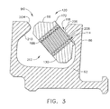
- balance weight 66 In order to install or position balance weight 66 within slot 90, bolt 70 is initially not attached or associated with balance weight 66. Instead, as shown in FIG. 3, balance weight 66 is inserted through opening 98 and upper section 122 of slot 90 without being associated with bolt 70. Insertion of balance weight 66 within slot 90 is typically carried out before balance weight retention member 62 is secured to rearward portion 54 of disk 22. As shown in FIG. 3, balance weight 66 is typically inserted through opening 98 and upper section 122 at a slanted angle, i.e., such that bottom surface 130 of balance weight 66 is not perpendicular to bottom surface 94 of slot 90.
- balance weight 66 can be inserted into slot 90 without the need of specially configured access ports or openings. Indeed, balance weight 66 can typically be inserted through opening 98 and upper section 122 of slot 90 at any position along the length thereof, e.g. along circumferential periphery 92.
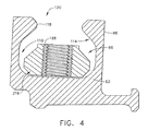
- balance weight 66 can then be moved, adjusted or rotated to a second position indicated generally as 216 in FIG. 4 within lower section 110 of slot 90.
- second position 216 balance weight 66 is fully within and movable in slot 90 (e.g., within lower section 110) and is also capable of receiving bolt 70.
- locking pin 196 can then be inserted into bore 200 to prevent bolt 70 from being accidentally disassociated or disconnected from balance weight 66 when bolt 70 is unscrewed.
- FIG. 5 shows turbine engine section 10 with a portion of the supporting structure indicated generally as 300 having formed therein respective outer and inner access holes 304 and 308 to provide a radially extending pathway indicated generally as 312 for access to balance assembly 58.
- a tool indicated generally as 316 is provided with an elongated shaft 320 that is inserted into pathway 312. Attached at the distal end of shaft 320 is a bolt driver section 324 that is configured or shaped for insertion into the inner driven section 328 of bolt head 176.
- bolt drive section 324 and driven section 328 have complementary hexagonal, square or other shaped cross-sections.
- balance weight 66 By rotating or turning shaft 320 in the desired direction, bolt 70 can be screwed or unscrewed in a direction that will cause balance weight 66 to be either moved away from bottom surface 94 of slot 90 such that balance weight 66 is in a secured position, or towards bottom surface 94 such that balance weight 66 is in unsecured position.
- balance weight 66 When balance weight 66 is in an unsecured position, it can then be moved anywhere along the circumferential length of slot 90 (e.g., within lower section 110) to any desired balancing position by simply rotating rotor 14 while tool 316 is in use. When balance weight 66 has reached the desired position, it can then secured within slot 90 as previously described.
- FIGs. 1-5 show only one balance weight 66, it should be understood that typically more than one balance weight 66 is inserted, positioned or present within slot 90. Indeed, typically a pair of balance weights 66 are inserted, positioned or present within slot 90. During initially balancing of rotor 14, the pair of balance weights 66 are typically moved within slot 90 such that they are approximately 180° opposite each other. As balance assembly 58 requires adjustment to trim balance or rebalance rotor 14, the balance weights 66 can be moved to different positions within slot 90 to achieve the desired degree of balancing. If three balance weights 66 are inserted within slot 90, they are typically moved initially within slot 90 to provide approximately 120° spacing (i.e., approximately equal spacing) from each other, and so on in like fashion or manner where more than three balance weights are inserted.
- approximately 120° spacing i.e., approximately equal spacing
- the positioning of balance weight(s) 66 within slot 90 can be adjusted as needed or desired to balance rotor 14.
- the positioning of balance weight(s) 66 can be adjusted after the initial operation of rotor 14 to provide subsequent or further balancing thereof, e.g., trim balancing.
- Access to balance weight(s) 66 to carrying out such subsequent or further balancing of rotor 14 is typically achieved by rotating or turning rotor 14 so that each respective balance weight 66 whose position needs to be adjusted is accessible by tool 316 via pathway 312. The position of the accessed balance weight 66 can then be adjusted with slot 90 as needed.
Landscapes
- Engineering & Computer Science (AREA)
- General Engineering & Computer Science (AREA)
- Mechanical Engineering (AREA)
- Physics & Mathematics (AREA)
- Acoustics & Sound (AREA)
- Aviation & Aerospace Engineering (AREA)
- Turbine Rotor Nozzle Sealing (AREA)
Applications Claiming Priority (2)
| Application Number | Priority Date | Filing Date | Title |
|---|---|---|---|
| US10/857,820 US20050265846A1 (en) | 2004-06-01 | 2004-06-01 | Balance assembly for rotary turbine component and method for installing and/or adjusting balance weight |
| US857820 | 2004-06-01 |
Publications (2)
| Publication Number | Publication Date |
|---|---|
| EP1602855A2 true EP1602855A2 (de) | 2005-12-07 |
| EP1602855A3 EP1602855A3 (de) | 2011-12-14 |
Family
ID=34941348
Family Applications (1)
| Application Number | Title | Priority Date | Filing Date |
|---|---|---|---|
| EP05253030A Withdrawn EP1602855A3 (de) | 2004-06-01 | 2005-05-18 | Einrichtung zum Auswuchten eines Turbinenrotors |
Country Status (4)
| Country | Link |
|---|---|
| US (1) | US20050265846A1 (de) |
| EP (1) | EP1602855A3 (de) |
| JP (1) | JP4688576B2 (de) |
| CA (1) | CA2508037A1 (de) |
Cited By (12)
| Publication number | Priority date | Publication date | Assignee | Title |
|---|---|---|---|---|
| GB2454568A (en) * | 2007-11-08 | 2009-05-13 | Gen Electric | Balancing weight is self-locking and is part of a rotating machine |
| EP2520767A1 (de) * | 2011-05-06 | 2012-11-07 | Rolls-Royce Deutschland & Co. KG | Gasturbinenauswuchtvorrichtung |
| EP2251529A3 (de) * | 2009-05-04 | 2013-10-16 | General Electric Company | Auswuchtgewichte einer Rotationsmaschine |
| CN103527259A (zh) * | 2012-07-06 | 2014-01-22 | 阿尔斯通技术有限公司 | 涡轮转子的减压平衡 |
| CN104919138A (zh) * | 2013-01-18 | 2015-09-16 | 斯奈克玛 | 用于涡轮发动机的旋转部件的平衡螺钉、装置和方法 |
| US9388697B2 (en) | 2012-07-17 | 2016-07-12 | Solar Turbines Incorporated | First stage compressor disk configured for balancing the compressor rotor assembly |
| WO2017093395A1 (en) * | 2015-12-02 | 2017-06-08 | Nuovo Pignone Tecnologie Srl | Device for balancing a rotor of a turbomachine |
| EP3222811A1 (de) * | 2016-03-24 | 2017-09-27 | Siemens Aktiengesellschaft | Schwingungsdämpfung in einer gasturbine |
| EP3404207A1 (de) * | 2017-04-28 | 2018-11-21 | Rolls-Royce Deutschland Ltd & Co KG | Rotoranordnung mit wuchtelement und verfahren zur montage eines wuchtelements |
| EP3587733A1 (de) * | 2018-06-21 | 2020-01-01 | United Technologies Corporation | System und verfahren zur auswuchtung eines rotors in einem zusammengesetzten motor |
| RU2754882C1 (ru) * | 2020-02-10 | 2021-09-08 | Мицубиси Пауэр, Лтд. | Рабочее колесо турбины |
| US12006833B2 (en) | 2022-09-02 | 2024-06-11 | General Electric Company | Shaft for a turbomachine |
Families Citing this family (26)
| Publication number | Priority date | Publication date | Assignee | Title |
|---|---|---|---|---|
| US7465146B2 (en) * | 2005-12-05 | 2008-12-16 | General Electric Company | Methods and systems for turbine rotor balancing |
| FR2896289B1 (fr) * | 2006-01-13 | 2008-03-28 | Snecma Sa | Masselotte d'equilibrage, disque de rotor en etant equipe, rotor et moteur d'aeronef les comportant |
| US7539594B2 (en) * | 2006-09-26 | 2009-05-26 | Axiam, Incorporated | Method and apparatus for geometric rotor stacking and balancing |
| US9297258B2 (en) | 2009-06-16 | 2016-03-29 | General Electric Company | Trapped spring balance weight and rotor assembly |
| EP2405100A1 (de) * | 2010-07-05 | 2012-01-11 | Siemens Aktiengesellschaft | Kombinierte Dichtungs- und Auswuchtanordnung für eine Turbinenlaufscheibe |
| US8668457B2 (en) | 2010-10-29 | 2014-03-11 | United Technologies Corporation | Gas turbine engine trim balance |
| GB201203303D0 (en) | 2012-02-27 | 2012-04-11 | Rolls Royce Plc | Balancing of rotor |
| EP2839114A1 (de) * | 2012-04-20 | 2015-02-25 | General Electric Company | Ausgleichsgewicht mit eingeschlossener feder und rotoranordnung |
| JP6131022B2 (ja) | 2012-10-30 | 2017-05-17 | 三菱重工業株式会社 | インペラ及びこれを備えた回転機械 |
| US9404367B2 (en) * | 2012-11-21 | 2016-08-02 | Solar Turbines Incorporated | Gas turbine engine compressor rotor assembly and balancing system |
| US9808889B2 (en) | 2014-01-15 | 2017-11-07 | Siemens Energy, Inc. | Gas turbine including sealing band and anti-rotation device |
| US9291065B2 (en) | 2013-03-08 | 2016-03-22 | Siemens Aktiengesellschaft | Gas turbine including bellyband seal anti-rotation device |
| CN103592080A (zh) * | 2013-10-29 | 2014-02-19 | 哈尔滨汽轮机厂有限责任公司 | 一种汽轮机高速动平衡用平衡块 |
| EP2905109A1 (de) * | 2014-02-07 | 2015-08-12 | Siemens Aktiengesellschaft | Verfahren und Vorrichtung zum Sichern eines in einem Gewindesitz eingeschraubten Gewindeelements, Verfahren zum Einbauen wenigstens eines Wuchtgewichts einer Turbine sowie Turbine |
| GB201409245D0 (en) * | 2014-05-23 | 2014-07-09 | Rolls Royce Plc | Rotor balancing |
| US10697300B2 (en) | 2017-12-14 | 2020-06-30 | Raytheon Technologies Corporation | Rotor balance weight system |
| CN108561269B (zh) * | 2018-03-16 | 2024-06-07 | 沈阳创新华夏机械制造有限公司 | 一种具有平衡调整装置的碳纤维叶片 |
| DE102019111211A1 (de) * | 2019-04-30 | 2020-11-05 | Rolls-Royce Deutschland Ltd & Co Kg | Vorrichtung zur Einstellung eines Wuchtzustandes eines rotierenden Teils eines Gasturbinentriebwerkes, ein Wuchtkörper und ein Gasturbinentriebwerk für ein Luftfahrzeug |
| US11448081B2 (en) * | 2019-10-18 | 2022-09-20 | Raytheon Technologies Corporation | Balanced circumferential seal |
| US11732585B2 (en) * | 2021-01-28 | 2023-08-22 | General Electric Company | Trapped rotatable weights to improve rotor balance |
| GB202218282D0 (en) * | 2022-12-06 | 2023-01-18 | Rolls Royce Plc | Rotor balancing apparatus |
| US12018579B1 (en) * | 2023-08-08 | 2024-06-25 | Rolls-Royce North American Technologies Inc. | Clocking balance weight rotor assembly for gas turbine engines |
| US12305528B2 (en) | 2023-08-08 | 2025-05-20 | Rolls-Royce North American Technologies Inc. | Rotor assembly for gas turbine engines with replaceable balance weight bands |
| US12018580B1 (en) * | 2023-08-08 | 2024-06-25 | Rolls-Royce North American Technologies Inc. | Rotor assembly for gas turbine engines with replaceable balance weight pins |
| US12601263B1 (en) * | 2024-11-26 | 2026-04-14 | Pratt & Whitney Canada Corp. | Radially captured in situ balancing masses for aircraft powerplant |
| US12553346B1 (en) * | 2025-03-10 | 2026-02-17 | Pratt & Whitney Canada Corp. | Gas turbine engine with rotational spool balancing system |
Family Cites Families (41)
| Publication number | Priority date | Publication date | Assignee | Title |
|---|---|---|---|---|
| US2492114A (en) * | 1944-11-03 | 1949-12-20 | Illinois Tool Works | Stud retainer |
| US2801074A (en) * | 1952-10-01 | 1957-07-30 | United Aircraft Corp | Blade retaining means |
| US2847187A (en) * | 1955-01-21 | 1958-08-12 | United Aircraft Corp | Blade locking means |
| US2853114A (en) * | 1955-08-30 | 1958-09-23 | South Chester Corp | Door or panel fastening device whereby a screw element is carried by the door or panel |
| US2964972A (en) * | 1958-07-10 | 1960-12-20 | Orenda Engines Ltd | Balances for rotating engine assemblies |
| US3263725A (en) * | 1964-07-02 | 1966-08-02 | Epstein Nat | Screw with cotter pin |
| US3564563A (en) * | 1968-01-09 | 1971-02-16 | Rex Chainbelt Inc | Adjustable quick acting fastener |
| CH494341A (de) * | 1968-07-26 | 1970-07-31 | Sulzer Ag | Rotor für Turbomaschinen |
| US3736811A (en) * | 1971-08-19 | 1973-06-05 | Gen Electric | Balance weight attachment for turbine wheels |
| JPS5223008B2 (de) * | 1972-06-19 | 1977-06-21 | ||
| CH572155A5 (de) * | 1974-05-27 | 1976-01-30 | Bbc Sulzer Turbomaschinen | |
| US3954350A (en) * | 1974-06-14 | 1976-05-04 | Motoren-Und Turbinen-Union Munchen Gmbh | Rotor having means for locking rotor blades to rotor disk |
| SE390330B (sv) * | 1975-04-28 | 1976-12-13 | Stal Laval Turbin Ab | Metod att placera och fixera balansvikter i ett laxstjertspar i en rotor samt verktyg for utforande av denna metod |
| US3985465A (en) * | 1975-06-25 | 1976-10-12 | United Technologies Corporation | Turbomachine with removable stator vane |
| JPS5416992U (de) * | 1977-07-08 | 1979-02-03 | ||
| FR2404212A1 (fr) * | 1977-09-23 | 1979-04-20 | Snecma | Dispositif d'equilibrage d'un rotor |
| JPS5852099B2 (ja) * | 1978-11-29 | 1983-11-19 | 株式会社日立製作所 | 回転体のバランスウエイト |
| US4453890A (en) * | 1981-06-18 | 1984-06-12 | General Electric Company | Blading system for a gas turbine engine |
| MX154678A (es) * | 1981-10-28 | 1987-09-23 | Armando Gamboa Mayoral | Automatizador para desobstruir la canula de succion de los aspiradores quirurgicos durante su uso |
| US4796465A (en) * | 1987-04-28 | 1989-01-10 | General Electric Company | Method and apparatus for monitoring turbomachine material |
| US4835827A (en) * | 1987-09-08 | 1989-06-06 | United Technologies Corporation | Method of balancing a rotor |
| US4848182A (en) * | 1987-09-08 | 1989-07-18 | United Technologies Corporation | Rotor balance system |
| US4926710A (en) * | 1987-09-08 | 1990-05-22 | United Technologies Corporation | Method of balancing bladed gas turbine engine rotor |
| US4784012A (en) * | 1987-09-08 | 1988-11-15 | United Technologies Corporation | Rotor balance system |
| US4803893A (en) * | 1987-09-24 | 1989-02-14 | United Technologies Corporation | High speed rotor balance system |
| US5011374A (en) * | 1987-11-17 | 1991-04-30 | General Electric Company | Method and apparatus for balancing turbine rotors |
| US4842485A (en) * | 1988-02-10 | 1989-06-27 | Westinghouse Electric Corp. | Balanced turbine rotor and method for making the same |
| IT1218207B (it) * | 1988-04-08 | 1990-04-12 | Nuovo Pignone Spa | Sistema per una rapida equilibratura di alberi rotanti,particolarmente adatto per turbine a gas |
| FR2630496B1 (fr) * | 1988-04-20 | 1993-05-14 | Snecma | Dispositif de correction de balourd d'un rotor de turbomachine |
| US4890981A (en) * | 1988-12-30 | 1990-01-02 | General Electric Company | Boltless rotor blade retainer |
| US5018943A (en) * | 1989-04-17 | 1991-05-28 | General Electric Company | Boltless balance weight for turbine rotors |
| JPH03179104A (ja) * | 1989-12-06 | 1991-08-05 | Mitsubishi Heavy Ind Ltd | 蒸気タービン車室 |
| US5167167A (en) * | 1991-11-18 | 1992-12-01 | United Technologies Corporation | Rotor trim balancing |
| USH1258H (en) * | 1992-09-16 | 1993-12-07 | The United States Of America As Represented By The Secretary Of The Air Force | Blade lock screw |
| US5545010A (en) * | 1993-05-13 | 1996-08-13 | Solar Turbines Incorporated | Method and apparatus for trim balancing a gas turbine engine |
| US6481969B2 (en) * | 1999-05-10 | 2002-11-19 | General Electric Company | Apparatus and methods for balancing turbine rotors |
| US6279420B1 (en) * | 1999-08-18 | 2001-08-28 | General Electric Co. | Balance weight for a rotary component in turbomachinery, methods of installation and installation tools |
| US6325581B1 (en) * | 2000-10-05 | 2001-12-04 | Joseph Abell | Steel setting device |
| GB0102757D0 (en) * | 2001-02-03 | 2001-03-21 | Rolls Royce Plc | Locking device |
| US6588298B2 (en) * | 2001-03-23 | 2003-07-08 | United Technologies Corporation | Rotor balancing system for turbomachinery |
| US6619924B2 (en) * | 2001-09-13 | 2003-09-16 | General Electric Company | Method and system for replacing a compressor blade |
-
2004
- 2004-06-01 US US10/857,820 patent/US20050265846A1/en not_active Abandoned
-
2005
- 2005-05-18 EP EP05253030A patent/EP1602855A3/de not_active Withdrawn
- 2005-05-19 CA CA002508037A patent/CA2508037A1/en not_active Abandoned
- 2005-05-31 JP JP2005159660A patent/JP4688576B2/ja not_active Expired - Fee Related
Cited By (21)
| Publication number | Priority date | Publication date | Assignee | Title |
|---|---|---|---|---|
| GB2454568B (en) * | 2007-11-08 | 2012-03-21 | Gen Electric | A rotating machine including a self-locking balance member |
| GB2454568A (en) * | 2007-11-08 | 2009-05-13 | Gen Electric | Balancing weight is self-locking and is part of a rotating machine |
| EP2251529A3 (de) * | 2009-05-04 | 2013-10-16 | General Electric Company | Auswuchtgewichte einer Rotationsmaschine |
| RU2535897C2 (ru) * | 2009-05-04 | 2014-12-20 | Дженерал Электрик Компани | Турбинная установка, содержащая роторную машину, и турбинная установка, содержащая балансировочный груз |
| EP2520767A1 (de) * | 2011-05-06 | 2012-11-07 | Rolls-Royce Deutschland & Co. KG | Gasturbinenauswuchtvorrichtung |
| US9017029B2 (en) | 2011-05-06 | 2015-04-28 | Rolls-Royce Deutschland Ltd & Co Kg | Gas-turbine balancing device |
| US9909422B2 (en) | 2012-07-06 | 2018-03-06 | General Electric Technology Gmbh | Reduced pressure balancing of a turbine rotor |
| CN103527259A (zh) * | 2012-07-06 | 2014-01-22 | 阿尔斯通技术有限公司 | 涡轮转子的减压平衡 |
| CN103527259B (zh) * | 2012-07-06 | 2015-08-19 | 阿尔斯通技术有限公司 | 涡轮转子的减压平衡 |
| US9388697B2 (en) | 2012-07-17 | 2016-07-12 | Solar Turbines Incorporated | First stage compressor disk configured for balancing the compressor rotor assembly |
| CN104919138A (zh) * | 2013-01-18 | 2015-09-16 | 斯奈克玛 | 用于涡轮发动机的旋转部件的平衡螺钉、装置和方法 |
| WO2017093395A1 (en) * | 2015-12-02 | 2017-06-08 | Nuovo Pignone Tecnologie Srl | Device for balancing a rotor of a turbomachine |
| US10731466B2 (en) | 2015-12-02 | 2020-08-04 | Nuovo Pignone Technologie Srl | Balancing device for a rotor including multidirectional balancing tools |
| WO2017162365A1 (en) | 2016-03-24 | 2017-09-28 | Siemens Aktiengesellschaft | Damping vibrations in a gas turbine |
| EP3222811A1 (de) * | 2016-03-24 | 2017-09-27 | Siemens Aktiengesellschaft | Schwingungsdämpfung in einer gasturbine |
| EP3404207A1 (de) * | 2017-04-28 | 2018-11-21 | Rolls-Royce Deutschland Ltd & Co KG | Rotoranordnung mit wuchtelement und verfahren zur montage eines wuchtelements |
| EP3587733A1 (de) * | 2018-06-21 | 2020-01-01 | United Technologies Corporation | System und verfahren zur auswuchtung eines rotors in einem zusammengesetzten motor |
| US10954793B2 (en) | 2018-06-21 | 2021-03-23 | Raytheon Technologies Corporation | System and method for balancing a rotor in an assembled engine |
| RU2754882C1 (ru) * | 2020-02-10 | 2021-09-08 | Мицубиси Пауэр, Лтд. | Рабочее колесо турбины |
| US12006833B2 (en) | 2022-09-02 | 2024-06-11 | General Electric Company | Shaft for a turbomachine |
| US12416238B2 (en) | 2022-09-02 | 2025-09-16 | General Electric Company | Shaft for a turbomachine |
Also Published As
| Publication number | Publication date |
|---|---|
| CA2508037A1 (en) | 2006-01-01 |
| EP1602855A3 (de) | 2011-12-14 |
| JP4688576B2 (ja) | 2011-05-25 |
| US20050265846A1 (en) | 2005-12-01 |
| JP2005351271A (ja) | 2005-12-22 |
Similar Documents
| Publication | Publication Date | Title |
|---|---|---|
| EP1602855A2 (de) | Einrichtung zum Auswuchten eines Turbinenrotors | |
| US6481969B2 (en) | Apparatus and methods for balancing turbine rotors | |
| RU2361090C2 (ru) | Устройство для балансировки вращающейся детали, в частности ротора турбореактивного двигателя | |
| US6929453B2 (en) | Locking spacer assembly for slotted turbine component | |
| CN1854485B (zh) | 用于燃气轮发动机的涡轮模组 | |
| US6279420B1 (en) | Balance weight for a rotary component in turbomachinery, methods of installation and installation tools | |
| US6619924B2 (en) | Method and system for replacing a compressor blade | |
| KR20070009391A (ko) | 접선 방향 회전자 블레이드의 로딩 및 로킹 방법과블레이드 설계 | |
| EP1229212B1 (de) | Schlussstück | |
| JP5608634B2 (ja) | 摩耗防止栓を備えるターボ機械のロータおよび摩耗防止栓 | |
| US8615874B2 (en) | Split fan wheel and split shroud assemblies and methods of manufacturing and assemblying the same | |
| US20140314550A1 (en) | Eccentric diaphragm adjusting pins for a gas turbine engine | |
| US3930751A (en) | Bucket locking mechanism | |
| JP2011102585A (ja) | 円周方向差込み型翼形部取付けシステム用の固定保持用スペーサ組立体 | |
| RU2279571C2 (ru) | Деталь ротора компрессора, усовершенствованная связь между дисками с системами лопаток на линии ротора компрессора, турбомашина и способ монтажа связи (варианты) | |
| US20090116954A1 (en) | Pitch control ring for stator vanes of a turbomachine | |
| EP1111193B1 (de) | Axiale Schaufelverriegelung für Turbomaschinen | |
| US7467925B2 (en) | Securing device for a moving blade of a turbomachine | |
| KR20020038530A (ko) | 교체 가능한 입구 안내 베인 조립체 및 교체시의 제거 방법 | |
| EP4063617B1 (de) | Halteanordnung mit verdrehsicherungsfunktion | |
| CN105793523A (zh) | 平衡式涡轮发动机部分以及涡轮发动机 | |
| EP3960987A1 (de) | Rotoranordnung für einen rotor einer gasturbine und gasturbine mit einer solchen rotoranordnung | |
| US7497658B2 (en) | Stacked reaction steam turbine stator assembly | |
| EP1785591A2 (de) | Axial- und Umfangsdichtung für eine Anordnung mit gestapeltem Rotor und/oder Stator | |
| JP2009115317A (ja) | 自己ロック式バランス調整部材を含む回転機械 |
Legal Events
| Date | Code | Title | Description |
|---|---|---|---|
| PUAI | Public reference made under article 153(3) epc to a published international application that has entered the european phase |
Free format text: ORIGINAL CODE: 0009012 |
|
| AK | Designated contracting states |
Kind code of ref document: A2 Designated state(s): AT BE BG CH CY CZ DE DK EE ES FI FR GB GR HU IE IS IT LI LT LU MC NL PL PT RO SE SI SK TR |
|
| AX | Request for extension of the european patent |
Extension state: AL BA HR LV MK YU |
|
| PUAL | Search report despatched |
Free format text: ORIGINAL CODE: 0009013 |
|
| AK | Designated contracting states |
Kind code of ref document: A3 Designated state(s): AT BE BG CH CY CZ DE DK EE ES FI FR GB GR HU IE IS IT LI LT LU MC NL PL PT RO SE SI SK TR |
|
| AX | Request for extension of the european patent |
Extension state: AL BA HR LV MK YU |
|
| RIC1 | Information provided on ipc code assigned before grant |
Ipc: F04D 29/66 20060101ALI20111109BHEP Ipc: F01D 5/02 20060101ALI20111109BHEP Ipc: G01M 1/36 20060101ALI20111109BHEP Ipc: F16F 15/32 20060101AFI20111109BHEP |
|
| AKY | No designation fees paid | ||
| REG | Reference to a national code |
Ref country code: DE Ref legal event code: R108 |
|
| REG | Reference to a national code |
Ref country code: DE Ref legal event code: R108 Effective date: 20120822 |
|
| STAA | Information on the status of an ep patent application or granted ep patent |
Free format text: STATUS: THE APPLICATION IS DEEMED TO BE WITHDRAWN |
|
| 18D | Application deemed to be withdrawn |
Effective date: 20120615 |