EP1603095A2 - Dispositif de détection - Google Patents
Dispositif de détection Download PDFInfo
- Publication number
- EP1603095A2 EP1603095A2 EP05106095A EP05106095A EP1603095A2 EP 1603095 A2 EP1603095 A2 EP 1603095A2 EP 05106095 A EP05106095 A EP 05106095A EP 05106095 A EP05106095 A EP 05106095A EP 1603095 A2 EP1603095 A2 EP 1603095A2
- Authority
- EP
- European Patent Office
- Prior art keywords
- optical
- sub
- matrix
- area
- detection device
- Prior art date
- Legal status (The legal status is an assumption and is not a legal conclusion. Google has not performed a legal analysis and makes no representation as to the accuracy of the status listed.)
- Granted
Links
- 238000001514 detection method Methods 0.000 title claims description 33
- 230000006870 function Effects 0.000 claims abstract description 53
- 239000011159 matrix material Substances 0.000 claims abstract description 42
- 230000003287 optical effect Effects 0.000 claims description 57
- 238000012544 monitoring process Methods 0.000 claims description 21
- 230000007613 environmental effect Effects 0.000 claims description 11
- 239000011248 coating agent Substances 0.000 claims description 8
- 238000000576 coating method Methods 0.000 claims description 8
- 239000000758 substrate Substances 0.000 claims description 5
- 239000011358 absorbing material Substances 0.000 claims description 2
- 238000000926 separation method Methods 0.000 claims 1
- 230000000007 visual effect Effects 0.000 abstract description 9
- 238000000034 method Methods 0.000 description 27
- 230000005855 radiation Effects 0.000 description 8
- 238000011156 evaluation Methods 0.000 description 7
- 239000013307 optical fiber Substances 0.000 description 7
- 238000001914 filtration Methods 0.000 description 6
- 230000015572 biosynthetic process Effects 0.000 description 5
- 239000000463 material Substances 0.000 description 5
- 230000005540 biological transmission Effects 0.000 description 4
- 238000012545 processing Methods 0.000 description 4
- 239000011521 glass Substances 0.000 description 3
- 238000009413 insulation Methods 0.000 description 3
- 238000004458 analytical method Methods 0.000 description 2
- 238000004140 cleaning Methods 0.000 description 2
- 230000004927 fusion Effects 0.000 description 2
- 230000010354 integration Effects 0.000 description 2
- 229920003023 plastic Polymers 0.000 description 2
- 230000009467 reduction Effects 0.000 description 2
- 230000004044 response Effects 0.000 description 2
- 238000004092 self-diagnosis Methods 0.000 description 2
- 238000007493 shaping process Methods 0.000 description 2
- 238000002207 thermal evaporation Methods 0.000 description 2
- 238000013459 approach Methods 0.000 description 1
- 239000003795 chemical substances by application Substances 0.000 description 1
- 238000004891 communication Methods 0.000 description 1
- 230000000295 complement effect Effects 0.000 description 1
- 230000008878 coupling Effects 0.000 description 1
- 238000010168 coupling process Methods 0.000 description 1
- 238000005859 coupling reaction Methods 0.000 description 1
- 230000001419 dependent effect Effects 0.000 description 1
- 238000011161 development Methods 0.000 description 1
- 238000010586 diagram Methods 0.000 description 1
- 239000000835 fiber Substances 0.000 description 1
- 239000003365 glass fiber Substances 0.000 description 1
- 238000010191 image analysis Methods 0.000 description 1
- 238000003384 imaging method Methods 0.000 description 1
- 239000003595 mist Substances 0.000 description 1
- 239000002245 particle Substances 0.000 description 1
- 230000008447 perception Effects 0.000 description 1
- 239000013308 plastic optical fiber Substances 0.000 description 1
- 238000007781 pre-processing Methods 0.000 description 1
- 229920006395 saturated elastomer Polymers 0.000 description 1
- 239000000779 smoke Substances 0.000 description 1
- 230000003595 spectral effect Effects 0.000 description 1
- 239000000725 suspension Substances 0.000 description 1
- 238000011144 upstream manufacturing Methods 0.000 description 1
Images




Classifications
-
- G—PHYSICS
- G08—SIGNALLING
- G08G—TRAFFIC CONTROL SYSTEMS
- G08G1/00—Traffic control systems for road vehicles
- G08G1/09—Arrangements for giving variable traffic instructions
- G08G1/0962—Arrangements for giving variable traffic instructions having an indicator mounted inside the vehicle, e.g. giving voice messages
- G08G1/0967—Systems involving transmission of highway information, e.g. weather, speed limits
- G08G1/096708—Systems involving transmission of highway information, e.g. weather, speed limits where the received information might be used to generate an automatic action on the vehicle control
- G08G1/096716—Systems involving transmission of highway information, e.g. weather, speed limits where the received information might be used to generate an automatic action on the vehicle control where the received information does not generate an automatic action on the vehicle control
-
- G—PHYSICS
- G01—MEASURING; TESTING
- G01J—MEASUREMENT OF INTENSITY, VELOCITY, SPECTRAL CONTENT, POLARISATION, PHASE OR PULSE CHARACTERISTICS OF INFRARED, VISIBLE OR ULTRAVIOLET LIGHT; COLORIMETRY; RADIATION PYROMETRY
- G01J1/00—Photometry, e.g. photographic exposure meter
- G01J1/42—Photometry, e.g. photographic exposure meter using electric radiation detectors
- G01J1/4228—Photometry, e.g. photographic exposure meter using electric radiation detectors arrangements with two or more detectors, e.g. for sensitivity compensation
-
- G—PHYSICS
- G01—MEASURING; TESTING
- G01N—INVESTIGATING OR ANALYSING MATERIALS BY DETERMINING THEIR CHEMICAL OR PHYSICAL PROPERTIES
- G01N21/00—Investigating or analysing materials by the use of optical means, i.e. using sub-millimetre waves, infrared, visible or ultraviolet light
- G01N21/17—Systems in which incident light is modified in accordance with the properties of the material investigated
- G01N21/47—Scattering, i.e. diffuse reflection
- G01N21/49—Scattering, i.e. diffuse reflection within a body or fluid
- G01N21/53—Scattering, i.e. diffuse reflection within a body or fluid within a flowing fluid, e.g. smoke
- G01N21/538—Scattering, i.e. diffuse reflection within a body or fluid within a flowing fluid, e.g. smoke for determining atmospheric attenuation and visibility
-
- G—PHYSICS
- G08—SIGNALLING
- G08G—TRAFFIC CONTROL SYSTEMS
- G08G1/00—Traffic control systems for road vehicles
- G08G1/01—Detecting movement of traffic to be counted or controlled
- G08G1/04—Detecting movement of traffic to be counted or controlled using optical or ultrasonic detectors
-
- G—PHYSICS
- G08—SIGNALLING
- G08G—TRAFFIC CONTROL SYSTEMS
- G08G1/00—Traffic control systems for road vehicles
- G08G1/09—Arrangements for giving variable traffic instructions
- G08G1/0962—Arrangements for giving variable traffic instructions having an indicator mounted inside the vehicle, e.g. giving voice messages
- G08G1/0967—Systems involving transmission of highway information, e.g. weather, speed limits
- G08G1/096733—Systems involving transmission of highway information, e.g. weather, speed limits where a selection of the information might take place
- G08G1/09675—Systems involving transmission of highway information, e.g. weather, speed limits where a selection of the information might take place where a selection from the received information takes place in the vehicle
-
- G—PHYSICS
- G08—SIGNALLING
- G08G—TRAFFIC CONTROL SYSTEMS
- G08G1/00—Traffic control systems for road vehicles
- G08G1/09—Arrangements for giving variable traffic instructions
- G08G1/0962—Arrangements for giving variable traffic instructions having an indicator mounted inside the vehicle, e.g. giving voice messages
- G08G1/0967—Systems involving transmission of highway information, e.g. weather, speed limits
- G08G1/096733—Systems involving transmission of highway information, e.g. weather, speed limits where a selection of the information might take place
- G08G1/096758—Systems involving transmission of highway information, e.g. weather, speed limits where a selection of the information might take place where no selection takes place on the transmitted or the received information
-
- G—PHYSICS
- G08—SIGNALLING
- G08G—TRAFFIC CONTROL SYSTEMS
- G08G1/00—Traffic control systems for road vehicles
- G08G1/09—Arrangements for giving variable traffic instructions
- G08G1/0962—Arrangements for giving variable traffic instructions having an indicator mounted inside the vehicle, e.g. giving voice messages
- G08G1/0967—Systems involving transmission of highway information, e.g. weather, speed limits
- G08G1/096766—Systems involving transmission of highway information, e.g. weather, speed limits where the system is characterised by the origin of the information transmission
- G08G1/096783—Systems involving transmission of highway information, e.g. weather, speed limits where the system is characterised by the origin of the information transmission where the origin of the information is a roadside individual element
-
- G—PHYSICS
- G08—SIGNALLING
- G08G—TRAFFIC CONTROL SYSTEMS
- G08G1/00—Traffic control systems for road vehicles
- G08G1/09—Arrangements for giving variable traffic instructions
- G08G1/0962—Arrangements for giving variable traffic instructions having an indicator mounted inside the vehicle, e.g. giving voice messages
- G08G1/0967—Systems involving transmission of highway information, e.g. weather, speed limits
- G08G1/096766—Systems involving transmission of highway information, e.g. weather, speed limits where the system is characterised by the origin of the information transmission
- G08G1/096791—Systems involving transmission of highway information, e.g. weather, speed limits where the system is characterised by the origin of the information transmission where the origin of the information is another vehicle
-
- H—ELECTRICITY
- H04—ELECTRIC COMMUNICATION TECHNIQUE
- H04N—PICTORIAL COMMUNICATION, e.g. TELEVISION
- H04N7/00—Television systems
- H04N7/18—Closed-circuit television [CCTV] systems, i.e. systems in which the video signal is not broadcast
- H04N7/181—Closed-circuit television [CCTV] systems, i.e. systems in which the video signal is not broadcast for receiving images from a plurality of remote sources
Definitions
- the present invention relates to a detection device of the type indicated in the pre-characterizing portion of claim 1.
- a detection device of this type which is installed on a vehicle, is known from DE-A-199 09 986.
- the main aim of the present invention is to suggest a detection device based on a multifunctional visual sensor which is simple, compact, cheap and highly reliable.
- the object of the invention is a detection device having the characteristics as listed in claim 1.
- the aforesaid functions are integrated into a CCD or CMOS matrix by dividing its sensitive area.
- Visibility detection becomes much "stronger” by combining active techniques (indirect, local and accurate measuring) with passive techniques (direct, extended and self-assured measuring).
- Visibility detection with active technique is based on an indirect measuring: what is detected is the backscattering radiation connected to fog density in the concerned volume. This is a simple, accurate and widely tested method. However, it is characterized by some disadvantages, i.e. it is a local (evaluation of fog density close to the sensor) and indirect measuring (correlation between fog density and visibility through half-empirical formulas).
- visibility detection with passive technique is based on a direct measuring of visibility over an extended area (fog evaluation in the space or scene before the sensor, by measuring light intensity and/or contrast) and enables to detect also the presence of a fog bank (or any other particle suspension compromising visibility, such as smoke) starting at a given distance (up to 50-100 m) from the sensor.
- a fog bank or any other particle suspension compromising visibility, such as smoke
- the portion of the sensitive area of the matrix dedicated to passive fog detection also performs functions of traffic monitoring and control.
- the device also integrates a temperature and relative humidity sensor, from which dew temperature can be obtained, which parameters can be useful in case of use of a mathematic model for predicting possible fog formation.
- Lighting detection together with visibility evaluation, becomes strictly necessary in order to modulate the intensity and/or adjust the frequency of emergency lights on the concerned road portion, so as to make said lights well visible to vehicles, however avoiding dangerous phenomena of drivers' dazzling.
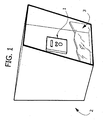
- FIG. 1 An integrated visual system for road applications is shown in figure 1 and is characterized by the following functions or a part thereof:
- the system architecture consists of:
- the system can be installed for instance on portals present on motorways, so as to monitor a relevant road portion.
- Figure 1 of the accompanying drawings shows an example of embodiment of the outer shell 2 of the device, having a front surface with an area 1 in which the real detection system (which shall be described in detail in the following) is placed, protected by an optical window 3.
- the real detection system which shall be described in detail in the following
- the sensitive area of the matrix 4 of the new system according to the present invention is divided into sub-areas dedicated to the following functions:
- Fog lowers visual efficiency since it reduces environmental contrast and therefore visible space, sometimes up to few meters. Basically, visual efficiency gets worse because of the lower depth perception, which is absolutely necessary to check and evaluate the position of objects in space.
- the visibility function is performed by combining two sub-areas: in the first one, the backscattering radiation generated by the presence of fog, which is related to visibility level, is measured with an active technique (i.e. via an emitter, for instance a LED or a laser diode); in the second sub-area, which coincides with the sub-area dedicated to traffic monitoring and control, road or motorway scene is acquired with a passive technique, and by means of algorithms of different type and complexity (e.g. contrast analysis; evaluation of parameters such as shading, ratio to horizon, overlapping, parallax, etc.) the presence of fog banks is detected, thus obtaining an evaluation on non-local visibility.
- an active technique i.e. via an emitter, for instance a LED or a laser diode
- road or motorway scene is acquired with a passive technique
- algorithms of different type and complexity e.g. contrast analysis; evaluation of parameters such as shading, ratio to horizon, overlapping, parallax, etc.
- FIG 3 shows schematically the principle of fog detection with active technique.
- numbers 5 and 6 refer to emitter and receiver, respectively.
- the area dedicated to traffic monitoring gives, beyond the number of vehicles traveling in some portions of the road network, also the type of flow (cars instead of trucks; average speed of traveling vehicles in case of queues) thanks to accurate image processing analyses.
- parameters that are useful for traffic control are measured, such as: speed (both for cars and trucks), safety distance, emergency lane occupied, queues, accidents.
- the function of environmental lighting is performed by a specific sub-area of the matrix or by a sub-area contained in the one dedicated to traffic monitoring.
- the function of dirt on optical window can be performed both with an active technique, i.e. with an emitter, and with a passive technique, i.e. without emitter, and can use as sensitive area a sub-area of the CMOS matrix or a separate receiving module.
- the system is equipped with an electro-optical emitting-receiving module separated from the visual matrix (though integrated into the sensor), so as to perform in an active manner the function of dirt on optical window.
- the function of dirt on optical window is performed in an active manner (i.e. via an emitter), but the receiver is said visual matrix, with a sub-area dedicated to said function or with a sub-area contained in the one dedicated to one of the aforesaid functions.
- the function of dirt on optical window is performed with a passive technique (for instance image analysis) in a matrix sub-area dedicated to said function, or in a sub-area contained in the one dedicated to one of the aforesaid functions (for instance the sub-area dedicated to scene monitoring).
- a passive technique for instance image analysis
- the monitoring of emitted optical power is performed through a sub-area dedicated to said function or by means of a photosensitive detector separated from the matrix or by means of an electronic circuit monitoring control current and environmental temperature.
- the system is further equipped with a sensor for measuring camera temperature (for instance a thermocouple or a PCB temperature sensor), so as to compensate matrix response when temperature varies in those functions requiring an absolute value as output.
- a sensor for measuring camera temperature for instance a thermocouple or a PCB temperature sensor
- the system is further equipped with a sensor for measuring outer temperature (for instance a thermocouple) and outer relative humidity so as to obtain dew temperature; these parameters enable to predict fog formation.
- a sensor for measuring outer temperature for instance a thermocouple
- outer relative humidity so as to obtain dew temperature
- the optical system enabling an integration of traffic monitoring, lighting and fog functions onto the same CMOS matrix can be carried out in accordance with two different arrangements:
- objective 30 for instance a microvideo lens, with a diameter of 12 mm and a length of 20 mm approximately
- optical axis inclined with respect to road plane so as to frame a road portion, shifted with respect to matrix center and orthogonal to matrix plane.
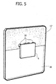
- the matrix 4 with its protection glass 16, having an opaque area 17 and openings 18, is placed behind the objective (see also Figure 5).
- the imaging optical system for performing scene monitoring and passive fog detection consists of a dedicated system based on micro-optical components.
- a glass or plastic optical fiber 9 (see also Figure 4) is used, having an end close to the matrix 4, provided with a ball lens 15 or a GRIN (gradient of index) lens 15, or also with no lens at all (as in 11), and a front end provided with a GRIN lens 13 or with a micro-optical component, or also with no lens at all (as in 10).
- the front end of the optical fiber 9 is associated to a high-pass (transparent at wavelengths above 800 nm)/interferential filter 8, which could also be absent, and to a collection lens 7, which can be a collection lens without filter or a collection lens with high-pass material with interferential coating.
- Optical fibers are a cheap and compact solution for modifying the direction of the field of view with respect to the direction orthogonal to the matrix.
- the field of view of the receiver should preferably be oriented in the direction of horizon or some degrees upwards.
- the collection lens 7 aims at focusing onto the optical fiber the incident radiation within a field of view of 7-8°.
- an anti-reflection coating should be applied onto the collection lens.
- the high-pass/interferential filter 8 aims at limiting the disturbance due to environmental light, filtering only radiation components in a band adjusted to the wavelength of the emitter (800-900 nm).
- the collection lens 7 can act as an optical band-pass filter, being made of a high-pass material, onto which a suitable interferential coating is laid, so that the spectral passing window is adjusted to the wavelength of the emitter.
- microlenses or GRIN lenses upstream or downstream from the optical fiber can improve fiber coupling efficiency and focusing onto CMOS matrix, respectively. In the latter case, not only is there an intensity gain, but also radiation spot onto the matrix is reduced.
- Another solution for filtering the signal of the emitter (referred to with number 31 in Figure 6) consists in using as emitter a LED modulated to a given frequency and an electronic band-pass filtering system at the frequency of the emitter. This solution is alternative or complementary to the use of the optical filter.
- a further solution for filtering the signal of the emitter 31 consists in using the environmental lighting signal to calculate background intensity and subtracting the latter from the signal of the fog detector. This solution is alternative to the filtering systems already described.
- an optical fiber 32 made of plastic or glass for collecting light is used, as in the case of passive technique fog function. No collection lens should however be used, since the detected signal has a sufficient intensity.
- Lighting function can also be carried out by calculating the average incident intensity on the area dedicated to traffic monitoring or to passive fog detection. In such case the same optical component as in these functions can be used.
- an optical system as the one of active technique fog function is used. In such case, however, the fields of view of emitter and receiver overlap in a smaller volume, including a portion of the optical window.
- the optical system related to this function can thus make use of one or more components among those listed for active technique fog function. If radiation is filtered electronically, a modulation frequency differing from the one used for fog function should preferably be used.
- optical collection components for the previous functions are systems including microlenses or microlenses-prims-microlenses.
- the system can consist or one or more matrixes of microlenses, arranged before the CMOS matrix.
- One or more microlenses can be present on each matrix.
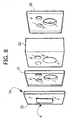
- it is provided for a matrix 21 of micro-optical components close to the sensor 4, and a matrix 20 of micro-optical components arranged towards the outside of the device.
- the optical system consists of one or more microlenses placed on different matrixes.
- the global optical chain can also comprise matrixes of microfilters, or simply optical windows partially covered with an interferential coating.
- one or more substrates of absorbing material can be used.
- these substrates can act as aperture stop, as stray light baffle or as field stop.
- an optical insulation element 22 with aperture stop placed between the two micro-optical matrixes, and an element 23 close to the sensor 4, acting as field stop.
- the prism deviates the optical axis (in case active fog and lighting functions are to be oriented upwards), whereas the microlens (or microlenses) focuses the transmitted optical signal.
- the senor is also provided with a protection window 16 ,made of glass or transparent plastic material, which also acts as a support for optical fibers (for the arrangement with standard optical elements) and, if necessary, with a prism; these optical components are inserted into holes made in said window.
- a protection window 16 made of glass or transparent plastic material, which also acts as a support for optical fibers (for the arrangement with standard optical elements) and, if necessary, with a prism; these optical components are inserted into holes made in said window.
- the protection window coincides with the substrate onto which the microlens matrix close to the photosensitive area is laid.
- Fig. 7 shows two LEDs 31 acting as emitters to which a beam shaping lens 33 is associated.
- References 31a, L, F, T symbolize, respectively, the emission lobes of the LEDs 31, the field of view for lighting function, the field of view for active technique fog function and the field of view for traffic monitoring and control.
- an optical insulation system is placed between the areas of the CMOS matrix dedicated to the various functions, which system consists of a partial coating of the surface of the matrix protection window, on the side towards the matrix, with a layer of absorbing or reflecting material, for instance by serigraphy or thermal evaporation.
- a layer of absorbing or reflecting material for instance by serigraphy or thermal evaporation.
- prisms also prism faces should be partially coated with a layer of absorbing or reflecting material, for instance by serigraphy or thermal evaporation.
- the optical protection window can be a microlens matrix, with no limitation concerning the laying of the absorbing coating.
- the visual sensor can be a CCD or CMOS sensor, with a different size depending on the number of performed functions and on the field of view designed for traffic monitoring and control.
- the CMOS sensor has a logarithmic response so as to have an almost linear development of visibility (in meters) depending on pixel light intensity, and thus a higher resolution for levels of visibility above 100 m.
- the color CMOS sensor can improve the strength of visibility evaluation algorithm; RGB levels in case of fog get saturated, thus making the image less brilliant and tending to white.
- Image acquisition can be complete on the whole matrix (in case of CCD) or limited to matrix sub-areas (in case of CMOS).
- the second option enables to use different parameters and acquisition speeds for each sub-area.
- the device is further equipped with an integrated electronic module, for signal acquisition and processing, and with a wireless data transmitting-receiving module, for communication with other identical or lower function sensors.
- the electronic module can compare the signals related to both types of measuring, and use in addition, if necessary, the environmental lighting signal, so as to give as output - through suitable algorithms - an accurate and self-assured visibility signal.
- the electronic module also uses temperature and humidity signals for evaluating visibility, in a data fusion algorithm improved with respect to the previous one, and predicting, if required, fog formation and thinning out.
- the base station can simultaneously connect via GSM/GPRS/UMTS to a central database for uploading data concerning a given road portion, and also for downloading information to be transmitted to traveling vehicles.
Landscapes
- General Physics & Mathematics (AREA)
- Physics & Mathematics (AREA)
- Life Sciences & Earth Sciences (AREA)
- Atmospheric Sciences (AREA)
- Engineering & Computer Science (AREA)
- General Health & Medical Sciences (AREA)
- Analytical Chemistry (AREA)
- Immunology (AREA)
- Pathology (AREA)
- Spectroscopy & Molecular Physics (AREA)
- Chemical & Material Sciences (AREA)
- Health & Medical Sciences (AREA)
- Multimedia (AREA)
- Signal Processing (AREA)
- Biochemistry (AREA)
- Traffic Control Systems (AREA)
- Investigating Or Analysing Materials By Optical Means (AREA)
- Transforming Light Signals Into Electric Signals (AREA)
- Measurement Of The Respiration, Hearing Ability, Form, And Blood Characteristics Of Living Organisms (AREA)
- Solid State Image Pick-Up Elements (AREA)
- Studio Devices (AREA)
- Eye Examination Apparatus (AREA)
- Measuring Pulse, Heart Rate, Blood Pressure Or Blood Flow (AREA)
- Measurement Of Radiation (AREA)
- Materials For Photolithography (AREA)
- Investigating Or Analyzing Materials By The Use Of Fluid Adsorption Or Reactions (AREA)
Applications Claiming Priority (3)
| Application Number | Priority Date | Filing Date | Title |
|---|---|---|---|
| ITTO20030770 | 2003-10-02 | ||
| IT000770A ITTO20030770A1 (it) | 2003-10-02 | 2003-10-02 | Dispositivo di rilevamento installabile lungo una |
| EP04017454A EP1521226B1 (fr) | 2003-10-02 | 2004-07-23 | Appareil pour détecter des conditions environnementales et pour contrôler et commander le trafic |
Related Parent Applications (2)
| Application Number | Title | Priority Date | Filing Date |
|---|---|---|---|
| EP04017454A Division EP1521226B1 (fr) | 2003-10-02 | 2004-07-23 | Appareil pour détecter des conditions environnementales et pour contrôler et commander le trafic |
| EP04017454.2 Division | 2004-07-23 |
Publications (3)
| Publication Number | Publication Date |
|---|---|
| EP1603095A2 true EP1603095A2 (fr) | 2005-12-07 |
| EP1603095A3 EP1603095A3 (fr) | 2006-01-04 |
| EP1603095B1 EP1603095B1 (fr) | 2007-02-28 |
Family
ID=34308163
Family Applications (2)
| Application Number | Title | Priority Date | Filing Date |
|---|---|---|---|
| EP05106095A Expired - Lifetime EP1603095B1 (fr) | 2003-10-02 | 2004-07-23 | Dispositif de détection |
| EP04017454A Expired - Lifetime EP1521226B1 (fr) | 2003-10-02 | 2004-07-23 | Appareil pour détecter des conditions environnementales et pour contrôler et commander le trafic |
Family Applications After (1)
| Application Number | Title | Priority Date | Filing Date |
|---|---|---|---|
| EP04017454A Expired - Lifetime EP1521226B1 (fr) | 2003-10-02 | 2004-07-23 | Appareil pour détecter des conditions environnementales et pour contrôler et commander le trafic |
Country Status (8)
| Country | Link |
|---|---|
| US (1) | US7817183B2 (fr) |
| EP (2) | EP1603095B1 (fr) |
| JP (2) | JP4234655B2 (fr) |
| CN (2) | CN1818613B (fr) |
| AT (2) | ATE355578T1 (fr) |
| DE (2) | DE602004001375T2 (fr) |
| ES (2) | ES2268549T3 (fr) |
| IT (1) | ITTO20030770A1 (fr) |
Families Citing this family (39)
| Publication number | Priority date | Publication date | Assignee | Title |
|---|---|---|---|---|
| ITMN20050049A1 (it) * | 2005-07-18 | 2007-01-19 | Balzanelli Sonia | Dispositivo visivo per veicoli in condizioni climatico-ambientali difficili |
| DE602005004544T2 (de) * | 2005-09-19 | 2008-04-30 | CRF Società Consortile per Azioni, Orbassano | Multifunktioneller optischer Sensor mit einer an Mikrolinsen gekoppelten Matrix von Photodetektoren |
| WO2008154736A1 (fr) | 2007-06-18 | 2008-12-24 | Leddartech Inc. | Système d'éclairage à fonctions d'assistance au conducteur |
| US8242476B2 (en) | 2005-12-19 | 2012-08-14 | Leddartech Inc. | LED object detection system and method combining complete reflection traces from individual narrow field-of-view channels |
| EP2158579B1 (fr) | 2007-06-18 | 2014-10-15 | Leddartech Inc. | Système d'éclairage avec fonctions de gestion de trafic |
| EP2232462B1 (fr) | 2007-12-21 | 2015-12-16 | Leddartech Inc. | Système et procédé de gestion de stationnement utilisant un système d'éclairage |
| WO2009079789A1 (fr) | 2007-12-21 | 2009-07-02 | Leddartech Inc. | Procédés et systèmes de détection et de télémétrie |
| KR101013578B1 (ko) | 2009-02-18 | 2011-02-14 | 김종헌 | 엘이디를 이용한 안개주의등 작동시스템 |
| TWM368888U (en) * | 2009-04-24 | 2009-11-11 | Cai Shuei Tian | Outdoor switch device for rain/frost detection |
| US8416300B2 (en) * | 2009-05-20 | 2013-04-09 | International Business Machines Corporation | Traffic system for enhancing driver visibility |
| CN102959599B (zh) | 2009-12-22 | 2015-07-15 | 莱达科技股份有限公司 | 用于交通检测的主动3d监控系统 |
| US8386156B2 (en) * | 2010-08-02 | 2013-02-26 | Siemens Industry, Inc. | System and method for lane-specific vehicle detection and control |
| EP2450865B1 (fr) * | 2010-11-04 | 2013-01-23 | Kapsch TrafficCom AG | Dispositifs et procédés de contrôle mobile pour véhicules |
| US8908159B2 (en) | 2011-05-11 | 2014-12-09 | Leddartech Inc. | Multiple-field-of-view scannerless optical rangefinder in high ambient background light |
| EP2721593B1 (fr) | 2011-06-17 | 2017-04-05 | Leddartech Inc. | Système et procédé de détection latérale et de caractérisation de circulation |
| DE102011086512B4 (de) * | 2011-11-16 | 2022-12-01 | Bayerische Motoren Werke Aktiengesellschaft | Nebeldetektion |
| CN102539383B (zh) * | 2012-01-09 | 2013-07-10 | 北京大学 | 散射式能见度仪中能见度测量方法 |
| US9235988B2 (en) | 2012-03-02 | 2016-01-12 | Leddartech Inc. | System and method for multipurpose traffic detection and characterization |
| CN103235088B (zh) * | 2013-04-17 | 2015-05-06 | 北方工业大学 | 实时评价机动车尾气对大气污染程度的系统及其运行方法 |
| ITRM20130274A1 (it) * | 2013-05-08 | 2014-11-09 | Smart I S R L | Sistema di sensori ottici distribuiti ed intelligenti per il controllo adattivo, predittivo ed on-demand dell'illuminazione pubblica |
| CN105324661B (zh) * | 2013-06-26 | 2019-07-05 | 飞利浦灯具控股公司 | 采用基于传感器的照明器探测能见度降低的区域及其移动方向的装置和方法 |
| CN103606282A (zh) * | 2013-11-06 | 2014-02-26 | 江苏省交通科学研究院股份有限公司 | 结冰预警视频检测系统 |
| DE102013018782A1 (de) | 2013-11-08 | 2015-05-13 | Audi Ag | Verfahren zum Betreiben eines Kommunikationssystems für Kraftfahrzeuge |
| CN105206074B (zh) * | 2014-06-16 | 2019-11-15 | 东阳市天杨建筑工程设计有限公司 | 公路交通引导方法及公路交通引导系统 |
| WO2016027244A1 (fr) * | 2014-08-20 | 2016-02-25 | Airtraff Di Mauro Zilio | Station pour la surveillance intégrée de l'environnement et de la circulation |
| WO2016038536A1 (fr) | 2014-09-09 | 2016-03-17 | Leddartech Inc. | Discrétisation de zone de détection |
| CN104700629B (zh) * | 2014-11-04 | 2017-08-04 | 南通大学 | 一种高速公路团雾的监测预警系统及方法 |
| US10274599B2 (en) * | 2016-06-01 | 2019-04-30 | Toyota Motor Engineering & Manufacturing North America, Inc. | LIDAR systems with expanded fields of view on a planar substrate |
| CN106023616A (zh) * | 2016-07-26 | 2016-10-12 | 马忠杰 | 一种防雾红绿灯 |
| CN107139870A (zh) * | 2017-05-22 | 2017-09-08 | 六六房车有限公司 | 一种基于房车环境检测的房车安全保护方法 |
| US11386498B1 (en) | 2017-09-06 | 2022-07-12 | State Farm Mutual Automobile Insurance Company | Using historical data for subrogation on a distributed ledger |
| US10872381B1 (en) | 2017-09-06 | 2020-12-22 | State Farm Mutual Automobile Insurance Company | Evidence oracles |
| FR3079614B1 (fr) * | 2018-03-30 | 2024-04-12 | Syscience | Procede et dispositif de mesure des conditions de visibilite |
| CN111274911B (zh) * | 2020-01-17 | 2020-12-01 | 河海大学 | 基于无线微波衰减特征迁移学习的浓雾监测方法 |
| CN112686105B (zh) * | 2020-12-18 | 2021-11-02 | 云南省交通规划设计研究院有限公司 | 一种基于视频图像多特征融合的雾浓度等级识别方法 |
| US20220198925A1 (en) * | 2020-12-21 | 2022-06-23 | Huawei Technologies Canada Co., Ltd. | Temporal detector scan image method, system, and medium for traffic signal control |
| CN113804655B (zh) * | 2021-09-10 | 2025-08-29 | 天津酷云网络科技有限公司 | 一种港口能见度监测系统及监测方法 |
| JP7780284B2 (ja) * | 2021-09-21 | 2025-12-04 | 株式会社Subaru | 車外環境認識装置 |
| CN120183206B (zh) * | 2025-05-22 | 2025-08-26 | 北京中控交安科技有限公司 | 一种一体化测雾型公路安全行车诱导装置及方法 |
Family Cites Families (19)
| Publication number | Priority date | Publication date | Assignee | Title |
|---|---|---|---|---|
| US2849701A (en) * | 1954-04-23 | 1958-08-26 | Tele Dynamics Inc | Highway condition indicating system |
| IT1013280B (it) * | 1974-05-28 | 1977-03-30 | Autostrade Concess Const | Sistema perfezionato per il control lo elettronico del traffico in tempo reale e per trasmissioni bidirezionali in codice e fonia fra centrale operativa e mezzi mobili |
| DE3537220A1 (de) * | 1985-10-16 | 1987-04-16 | Joerg Prof Dr Ing Albertz | Optoelektronische kamera |
| AU2268088A (en) * | 1987-08-25 | 1989-03-31 | Elin-Union Aktiengesellschaft Fur Elektrische Industrie | Improved road traffic-control system |
| DE4200057A1 (de) * | 1992-01-03 | 1993-07-08 | Josef Dipl Ing Zink | Lasermesssystem zur messung physikalischer messgroessen |
| FR2689072A1 (fr) * | 1992-03-31 | 1993-10-01 | Valeo Vision | Dispositif d'éclairage et/ou de signalisation utilisé en situation de brouillard. |
| US6396397B1 (en) * | 1993-02-26 | 2002-05-28 | Donnelly Corporation | Vehicle imaging system with stereo imaging |
| JPH07318650A (ja) | 1994-05-24 | 1995-12-08 | Mitsubishi Electric Corp | 障害物検知装置 |
| EP0879158B1 (fr) * | 1996-02-13 | 1999-07-28 | Marquardt GmbH | Detecteur optique |
| GB9606477D0 (en) * | 1996-03-27 | 1996-06-05 | Rover Group | A sensing system for a vehicle |
| US6611610B1 (en) * | 1997-04-02 | 2003-08-26 | Gentex Corporation | Vehicle lamp control |
| DE19730341A1 (de) * | 1997-07-15 | 1999-01-21 | Sick Ag | Verfahren zum Betrieb einer opto-elektronischen Sensoranordnung |
| DE19755008B4 (de) * | 1997-12-11 | 2007-01-04 | Conti Temic Microelectronic Gmbh | Verfahren zum Betreiben eines Multifunktionalen Innenspiegels |
| DE19909986C2 (de) * | 1999-03-06 | 2002-08-29 | Kostal Leopold Gmbh & Co Kg | Optoelektronische Überwachungseinrichtung für ein Kraftfahrzeug |
| US6189808B1 (en) * | 1999-04-15 | 2001-02-20 | Mccord Winn Textron Inc. | Automatically controlled washer system for headlamps |
| US6812855B1 (en) * | 1999-08-24 | 2004-11-02 | Sekisui Jushi Kabushiki Kaisha | Road traffic weather observation system and self-emission road sign system |
| US6422062B1 (en) * | 2000-08-29 | 2002-07-23 | Delphi Technologies, Inc. | Integrated glass fog sensor unit |
| US6662099B2 (en) * | 2001-05-22 | 2003-12-09 | Massachusetts Institute Of Technology | Wireless roadway monitoring system |
| ITTO20020950A1 (it) * | 2002-11-05 | 2004-05-06 | Fiat Ricerche | Sistema di visione integrato multifunzionale, con matrice |
-
2003
- 2003-10-02 IT IT000770A patent/ITTO20030770A1/it unknown
-
2004
- 2004-07-23 DE DE602004001375T patent/DE602004001375T2/de not_active Expired - Lifetime
- 2004-07-23 ES ES04017454T patent/ES2268549T3/es not_active Expired - Lifetime
- 2004-07-23 AT AT05106095T patent/ATE355578T1/de not_active IP Right Cessation
- 2004-07-23 AT AT04017454T patent/ATE331999T1/de not_active IP Right Cessation
- 2004-07-23 EP EP05106095A patent/EP1603095B1/fr not_active Expired - Lifetime
- 2004-07-23 EP EP04017454A patent/EP1521226B1/fr not_active Expired - Lifetime
- 2004-07-23 DE DE602004005012T patent/DE602004005012T2/de not_active Expired - Lifetime
- 2004-07-23 ES ES05106095T patent/ES2281884T3/es not_active Expired - Lifetime
- 2004-09-09 JP JP2004262206A patent/JP4234655B2/ja not_active Expired - Fee Related
- 2004-09-14 US US10/939,512 patent/US7817183B2/en not_active Expired - Fee Related
- 2004-09-15 CN CN2006100049189A patent/CN1818613B/zh not_active Expired - Fee Related
- 2004-09-15 CN CN2004100785624A patent/CN1603792B/zh not_active Expired - Fee Related
-
2006
- 2006-02-06 JP JP2006027970A patent/JP4485477B2/ja not_active Expired - Fee Related
Also Published As
| Publication number | Publication date |
|---|---|
| ES2268549T3 (es) | 2007-03-16 |
| EP1521226B1 (fr) | 2006-06-28 |
| EP1521226A1 (fr) | 2005-04-06 |
| DE602004001375D1 (de) | 2006-08-10 |
| ATE331999T1 (de) | 2006-07-15 |
| CN1603792B (zh) | 2010-11-17 |
| DE602004005012T2 (de) | 2007-11-15 |
| JP4234655B2 (ja) | 2009-03-04 |
| CN1818613A (zh) | 2006-08-16 |
| US7817183B2 (en) | 2010-10-19 |
| CN1603792A (zh) | 2005-04-06 |
| EP1603095A3 (fr) | 2006-01-04 |
| EP1603095B1 (fr) | 2007-02-28 |
| JP4485477B2 (ja) | 2010-06-23 |
| ITTO20030770A1 (it) | 2005-04-03 |
| CN1818613B (zh) | 2012-01-11 |
| ATE355578T1 (de) | 2006-03-15 |
| ES2281884T3 (es) | 2007-10-01 |
| US20050072907A1 (en) | 2005-04-07 |
| JP2006139808A (ja) | 2006-06-01 |
| JP2005117639A (ja) | 2005-04-28 |
| DE602004001375T2 (de) | 2007-05-03 |
| DE602004005012D1 (de) | 2007-04-12 |
Similar Documents
| Publication | Publication Date | Title |
|---|---|---|
| EP1603095B1 (fr) | Dispositif de détection | |
| EP1418089B1 (fr) | Système optique multifonctionel intégré avec une matrice CMOS ou CCD | |
| US6067110A (en) | Object recognizing device | |
| KR101903981B1 (ko) | 카메라와 라이트를 사용하여 창에 떨어지는 빗방울 감지 | |
| JP3163889U (ja) | 運転における補助のための、及び/又は自動車に設けられたシステムを自動的に作動させるための、自動車に搭載される光センサデバイス | |
| CN100573891C (zh) | 包含耦合至微透镜矩阵的光探测器矩阵的多功能光传感器 | |
| JP6333238B2 (ja) | カメラ及び照明を用いたガラス面の雨滴検出 | |
| CN105830428A (zh) | 目标检测设备、移动体设备控制系统及其程序 | |
| EP3225020A1 (fr) | Dispositif d'imagerie, détecteur d'objet, et système de commande de dispositif mobile | |
| US20120113258A1 (en) | Camera system and method for operating a camera system for a motor vehicle | |
| JP2007060158A (ja) | 撮像モジュール | |
| WO2016084359A1 (fr) | Dispositif d'imagerie, détecteur d'objet, et système de commande de dispositif mobile | |
| KR102479392B1 (ko) | 차량용 블랙아이스 감지시스템 | |
| JPH0712938A (ja) | 車両用レーザーレーダー装置 | |
| KR102689136B1 (ko) | 라이다와 카메라 일체형의 촬영 장치 및 그의 처리 방법 | |
| JP5891723B2 (ja) | 撮像方法および撮像ユニット | |
| JP4281177B2 (ja) | 車載用撮像装置 | |
| JPH0593981U (ja) | グレアセンサ |
Legal Events
| Date | Code | Title | Description |
|---|---|---|---|
| PUAI | Public reference made under article 153(3) epc to a published international application that has entered the european phase |
Free format text: ORIGINAL CODE: 0009012 |
|
| PUAL | Search report despatched |
Free format text: ORIGINAL CODE: 0009013 |
|
| AC | Divisional application: reference to earlier application |
Ref document number: 1521226 Country of ref document: EP Kind code of ref document: P |
|
| AK | Designated contracting states |
Kind code of ref document: A2 Designated state(s): AT BE BG CH CY CZ DE DK EE ES FI FR GB GR HU IE IT LI LU MC NL PL PT RO SE SI SK TR |
|
| AX | Request for extension of the european patent |
Extension state: AL BA HR MK YU |
|
| AK | Designated contracting states |
Kind code of ref document: A3 Designated state(s): AT BE BG CH CY CZ DE DK EE ES FI FR GB GR HU IE IT LI LU MC NL PL PT RO SE SI SK TR |
|
| AX | Request for extension of the european patent |
Extension state: AL BA HR MK YU |
|
| RIC1 | Information provided on ipc code assigned before grant |
Ipc: B60R 1/00 20060101ALI20051116BHEP Ipc: G01N 21/53 20060101ALI20051116BHEP Ipc: G08G 1/09 20060101AFI20051116BHEP Ipc: G08G 1/04 20060101ALI20051116BHEP Ipc: H04N 7/18 20060101ALI20051116BHEP Ipc: G08G 1/0967 20060101ALI20051116BHEP |
|
| RIN1 | Information on inventor provided before grant (corrected) |
Inventor name: VISINTAINER, FILIPPO C/O C.R.F. SOCIETAE CONSORTIL Inventor name: LIOTTI, LUCA, C/O C.R.F. SOCIETAE CONSORTILE Inventor name: REPETTO, PIERMARIO, C/O C.R.F. SOCIETAE CONSORTILE Inventor name: DARIN, MARCO, C/O C.R.F. SOCIETAE CONSORTILE Inventor name: MOSCA, EMILIO, C/O C.R.F. SOCIETAE CONSORTILE Inventor name: PALLARO, NEREO, C/O SOCIETAE CONSORTILE PER AZIONI |
|
| 17P | Request for examination filed |
Effective date: 20060609 |
|
| 17Q | First examination report despatched |
Effective date: 20060714 |
|
| AKX | Designation fees paid |
Designated state(s): AT BE BG CH CY CZ DE DK EE ES FI FR GB GR HU IE IT LI LU MC NL PL PT RO SE SI SK TR |
|
| GRAP | Despatch of communication of intention to grant a patent |
Free format text: ORIGINAL CODE: EPIDOSNIGR1 |
|
| RIN1 | Information on inventor provided before grant (corrected) |
Inventor name: PALLARO, NEREO, C/O C.R.F. SOCIETA CONSORTILE Inventor name: VISINTAINER, FILIPPO C/O C.R.F. SOCIETA CONSORTILE Inventor name: LIOTTI, LUCA, C/O C.R.F. SOCIETA CONSORTILE Inventor name: MOSCA, EMILIO, C/O C.R.F. SOCIETA CONSORTILE Inventor name: REPETTO, PIERMARIO, C/O C.R.F. SOCIETA CONSORTILE Inventor name: DARIN, MARCO, C/O C.R.F. SOCIETA CONSORTILE |
|
| GRAS | Grant fee paid |
Free format text: ORIGINAL CODE: EPIDOSNIGR3 |
|
| GRAA | (expected) grant |
Free format text: ORIGINAL CODE: 0009210 |
|
| AC | Divisional application: reference to earlier application |
Ref document number: 1521226 Country of ref document: EP Kind code of ref document: P |
|
| AK | Designated contracting states |
Kind code of ref document: B1 Designated state(s): AT BE BG CH CY CZ DE DK EE ES FI FR GB GR HU IE IT LI LU MC NL PL PT RO SE SI SK TR |
|
| PG25 | Lapsed in a contracting state [announced via postgrant information from national office to epo] |
Ref country code: NL Free format text: LAPSE BECAUSE OF FAILURE TO SUBMIT A TRANSLATION OF THE DESCRIPTION OR TO PAY THE FEE WITHIN THE PRESCRIBED TIME-LIMIT Effective date: 20070228 Ref country code: AT Free format text: LAPSE BECAUSE OF FAILURE TO SUBMIT A TRANSLATION OF THE DESCRIPTION OR TO PAY THE FEE WITHIN THE PRESCRIBED TIME-LIMIT Effective date: 20070228 Ref country code: DK Free format text: LAPSE BECAUSE OF FAILURE TO SUBMIT A TRANSLATION OF THE DESCRIPTION OR TO PAY THE FEE WITHIN THE PRESCRIBED TIME-LIMIT Effective date: 20070228 Ref country code: SI Free format text: LAPSE BECAUSE OF FAILURE TO SUBMIT A TRANSLATION OF THE DESCRIPTION OR TO PAY THE FEE WITHIN THE PRESCRIBED TIME-LIMIT Effective date: 20070228 Ref country code: PL Free format text: LAPSE BECAUSE OF FAILURE TO SUBMIT A TRANSLATION OF THE DESCRIPTION OR TO PAY THE FEE WITHIN THE PRESCRIBED TIME-LIMIT Effective date: 20070228 Ref country code: FI Free format text: LAPSE BECAUSE OF FAILURE TO SUBMIT A TRANSLATION OF THE DESCRIPTION OR TO PAY THE FEE WITHIN THE PRESCRIBED TIME-LIMIT Effective date: 20070228 |
|
| REG | Reference to a national code |
Ref country code: GB Ref legal event code: FG4D |
|
| REG | Reference to a national code |
Ref country code: CH Ref legal event code: NV Representative=s name: ISLER & PEDRAZZINI AG Ref country code: CH Ref legal event code: EP |
|
| REF | Corresponds to: |
Ref document number: 602004005012 Country of ref document: DE Date of ref document: 20070412 Kind code of ref document: P |
|
| REG | Reference to a national code |
Ref country code: IE Ref legal event code: FG4D |
|
| REG | Reference to a national code |
Ref country code: SE Ref legal event code: TRGR |
|
| PG25 | Lapsed in a contracting state [announced via postgrant information from national office to epo] |
Ref country code: BG Free format text: LAPSE BECAUSE OF FAILURE TO SUBMIT A TRANSLATION OF THE DESCRIPTION OR TO PAY THE FEE WITHIN THE PRESCRIBED TIME-LIMIT Effective date: 20070528 |
|
| ET | Fr: translation filed | ||
| PG25 | Lapsed in a contracting state [announced via postgrant information from national office to epo] |
Ref country code: PT Free format text: LAPSE BECAUSE OF FAILURE TO SUBMIT A TRANSLATION OF THE DESCRIPTION OR TO PAY THE FEE WITHIN THE PRESCRIBED TIME-LIMIT Effective date: 20070730 |
|
| NLV1 | Nl: lapsed or annulled due to failure to fulfill the requirements of art. 29p and 29m of the patents act | ||
| REG | Reference to a national code |
Ref country code: CH Ref legal event code: PCAR Free format text: ISLER & PEDRAZZINI AG;POSTFACH 1772;8027 ZUERICH (CH) |
|
| REG | Reference to a national code |
Ref country code: ES Ref legal event code: FG2A Ref document number: 2281884 Country of ref document: ES Kind code of ref document: T3 |
|
| PG25 | Lapsed in a contracting state [announced via postgrant information from national office to epo] |
Ref country code: SK Free format text: LAPSE BECAUSE OF FAILURE TO SUBMIT A TRANSLATION OF THE DESCRIPTION OR TO PAY THE FEE WITHIN THE PRESCRIBED TIME-LIMIT Effective date: 20070228 |
|
| PG25 | Lapsed in a contracting state [announced via postgrant information from national office to epo] |
Ref country code: RO Free format text: LAPSE BECAUSE OF FAILURE TO SUBMIT A TRANSLATION OF THE DESCRIPTION OR TO PAY THE FEE WITHIN THE PRESCRIBED TIME-LIMIT Effective date: 20070228 Ref country code: CZ Free format text: LAPSE BECAUSE OF FAILURE TO SUBMIT A TRANSLATION OF THE DESCRIPTION OR TO PAY THE FEE WITHIN THE PRESCRIBED TIME-LIMIT Effective date: 20070228 |
|
| PLBE | No opposition filed within time limit |
Free format text: ORIGINAL CODE: 0009261 |
|
| STAA | Information on the status of an ep patent application or granted ep patent |
Free format text: STATUS: NO OPPOSITION FILED WITHIN TIME LIMIT |
|
| 26N | No opposition filed |
Effective date: 20071129 |
|
| PG25 | Lapsed in a contracting state [announced via postgrant information from national office to epo] |
Ref country code: MC Free format text: LAPSE BECAUSE OF NON-PAYMENT OF DUE FEES Effective date: 20070731 Ref country code: GR Free format text: LAPSE BECAUSE OF FAILURE TO SUBMIT A TRANSLATION OF THE DESCRIPTION OR TO PAY THE FEE WITHIN THE PRESCRIBED TIME-LIMIT Effective date: 20070529 |
|
| PG25 | Lapsed in a contracting state [announced via postgrant information from national office to epo] |
Ref country code: IE Free format text: LAPSE BECAUSE OF NON-PAYMENT OF DUE FEES Effective date: 20070723 |
|
| PG25 | Lapsed in a contracting state [announced via postgrant information from national office to epo] |
Ref country code: EE Free format text: LAPSE BECAUSE OF FAILURE TO SUBMIT A TRANSLATION OF THE DESCRIPTION OR TO PAY THE FEE WITHIN THE PRESCRIBED TIME-LIMIT Effective date: 20070228 |
|
| PG25 | Lapsed in a contracting state [announced via postgrant information from national office to epo] |
Ref country code: CY Free format text: LAPSE BECAUSE OF FAILURE TO SUBMIT A TRANSLATION OF THE DESCRIPTION OR TO PAY THE FEE WITHIN THE PRESCRIBED TIME-LIMIT Effective date: 20070228 |
|
| PG25 | Lapsed in a contracting state [announced via postgrant information from national office to epo] |
Ref country code: LU Free format text: LAPSE BECAUSE OF NON-PAYMENT OF DUE FEES Effective date: 20070723 |
|
| PG25 | Lapsed in a contracting state [announced via postgrant information from national office to epo] |
Ref country code: HU Free format text: LAPSE BECAUSE OF FAILURE TO SUBMIT A TRANSLATION OF THE DESCRIPTION OR TO PAY THE FEE WITHIN THE PRESCRIBED TIME-LIMIT Effective date: 20070901 Ref country code: TR Free format text: LAPSE BECAUSE OF FAILURE TO SUBMIT A TRANSLATION OF THE DESCRIPTION OR TO PAY THE FEE WITHIN THE PRESCRIBED TIME-LIMIT Effective date: 20070228 |
|
| REG | Reference to a national code |
Ref country code: FR Ref legal event code: PLFP Year of fee payment: 13 |
|
| REG | Reference to a national code |
Ref country code: FR Ref legal event code: PLFP Year of fee payment: 14 |
|
| PGFP | Annual fee paid to national office [announced via postgrant information from national office to epo] |
Ref country code: CH Payment date: 20170613 Year of fee payment: 12 Ref country code: ES Payment date: 20170830 Year of fee payment: 14 |
|
| PGFP | Annual fee paid to national office [announced via postgrant information from national office to epo] |
Ref country code: SE Payment date: 20170727 Year of fee payment: 14 Ref country code: BE Payment date: 20170725 Year of fee payment: 14 |
|
| REG | Reference to a national code |
Ref country code: FR Ref legal event code: PLFP Year of fee payment: 15 |
|
| REG | Reference to a national code |
Ref country code: CH Ref legal event code: PL |
|
| GBPC | Gb: european patent ceased through non-payment of renewal fee |
Effective date: 20180723 |
|
| REG | Reference to a national code |
Ref country code: BE Ref legal event code: MM Effective date: 20180731 |
|
| PG25 | Lapsed in a contracting state [announced via postgrant information from national office to epo] |
Ref country code: GB Free format text: LAPSE BECAUSE OF NON-PAYMENT OF DUE FEES Effective date: 20180723 Ref country code: CH Free format text: LAPSE BECAUSE OF NON-PAYMENT OF DUE FEES Effective date: 20180731 Ref country code: LI Free format text: LAPSE BECAUSE OF NON-PAYMENT OF DUE FEES Effective date: 20180731 |
|
| PG25 | Lapsed in a contracting state [announced via postgrant information from national office to epo] |
Ref country code: SE Free format text: LAPSE BECAUSE OF NON-PAYMENT OF DUE FEES Effective date: 20180724 Ref country code: BE Free format text: LAPSE BECAUSE OF NON-PAYMENT OF DUE FEES Effective date: 20180731 |
|
| REG | Reference to a national code |
Ref country code: ES Ref legal event code: FD2A Effective date: 20190917 |
|
| PG25 | Lapsed in a contracting state [announced via postgrant information from national office to epo] |
Ref country code: ES Free format text: LAPSE BECAUSE OF NON-PAYMENT OF DUE FEES Effective date: 20180724 |
|
| PGFP | Annual fee paid to national office [announced via postgrant information from national office to epo] |
Ref country code: DE Payment date: 20200729 Year of fee payment: 17 Ref country code: FR Payment date: 20200728 Year of fee payment: 17 |
|
| PGFP | Annual fee paid to national office [announced via postgrant information from national office to epo] |
Ref country code: IT Payment date: 20200708 Year of fee payment: 17 |
|
| REG | Reference to a national code |
Ref country code: DE Ref legal event code: R119 Ref document number: 602004005012 Country of ref document: DE |
|
| PG25 | Lapsed in a contracting state [announced via postgrant information from national office to epo] |
Ref country code: DE Free format text: LAPSE BECAUSE OF NON-PAYMENT OF DUE FEES Effective date: 20220201 |
|
| PG25 | Lapsed in a contracting state [announced via postgrant information from national office to epo] |
Ref country code: FR Free format text: LAPSE BECAUSE OF NON-PAYMENT OF DUE FEES Effective date: 20210731 |
|
| PG25 | Lapsed in a contracting state [announced via postgrant information from national office to epo] |
Ref country code: IT Free format text: LAPSE BECAUSE OF NON-PAYMENT OF DUE FEES Effective date: 20210723 |