EP1603103A2 - Dispositif d'affichage - Google Patents
Dispositif d'affichage Download PDFInfo
- Publication number
- EP1603103A2 EP1603103A2 EP05104864A EP05104864A EP1603103A2 EP 1603103 A2 EP1603103 A2 EP 1603103A2 EP 05104864 A EP05104864 A EP 05104864A EP 05104864 A EP05104864 A EP 05104864A EP 1603103 A2 EP1603103 A2 EP 1603103A2
- Authority
- EP
- European Patent Office
- Prior art keywords
- gradation level
- gradation
- input image
- subfields
- level
- Prior art date
- Legal status (The legal status is an assumption and is not a legal conclusion. Google has not performed a legal analysis and makes no representation as to the accuracy of the status listed.)
- Withdrawn
Links
Images


Classifications
-
- G—PHYSICS
- G09—EDUCATION; CRYPTOGRAPHY; DISPLAY; ADVERTISING; SEALS
- G09G—ARRANGEMENTS OR CIRCUITS FOR CONTROL OF INDICATING DEVICES USING STATIC MEANS TO PRESENT VARIABLE INFORMATION
- G09G3/00—Control arrangements or circuits, of interest only in connection with visual indicators other than cathode-ray tubes
- G09G3/20—Control arrangements or circuits, of interest only in connection with visual indicators other than cathode-ray tubes for presentation of an assembly of a number of characters, e.g. a page, by composing the assembly by combination of individual elements arranged in a matrix no fixed position being assigned to or needed to be assigned to the individual characters or partial characters
- G09G3/22—Control arrangements or circuits, of interest only in connection with visual indicators other than cathode-ray tubes for presentation of an assembly of a number of characters, e.g. a page, by composing the assembly by combination of individual elements arranged in a matrix no fixed position being assigned to or needed to be assigned to the individual characters or partial characters using controlled light sources
- G09G3/28—Control arrangements or circuits, of interest only in connection with visual indicators other than cathode-ray tubes for presentation of an assembly of a number of characters, e.g. a page, by composing the assembly by combination of individual elements arranged in a matrix no fixed position being assigned to or needed to be assigned to the individual characters or partial characters using controlled light sources using luminous gas-discharge panels, e.g. plasma panels
- G09G3/288—Control arrangements or circuits, of interest only in connection with visual indicators other than cathode-ray tubes for presentation of an assembly of a number of characters, e.g. a page, by composing the assembly by combination of individual elements arranged in a matrix no fixed position being assigned to or needed to be assigned to the individual characters or partial characters using controlled light sources using luminous gas-discharge panels, e.g. plasma panels using AC panels
- G09G3/296—Driving circuits for producing the waveforms applied to the driving electrodes
-
- G—PHYSICS
- G09—EDUCATION; CRYPTOGRAPHY; DISPLAY; ADVERTISING; SEALS
- G09G—ARRANGEMENTS OR CIRCUITS FOR CONTROL OF INDICATING DEVICES USING STATIC MEANS TO PRESENT VARIABLE INFORMATION
- G09G3/00—Control arrangements or circuits, of interest only in connection with visual indicators other than cathode-ray tubes
- G09G3/20—Control arrangements or circuits, of interest only in connection with visual indicators other than cathode-ray tubes for presentation of an assembly of a number of characters, e.g. a page, by composing the assembly by combination of individual elements arranged in a matrix no fixed position being assigned to or needed to be assigned to the individual characters or partial characters
- G09G3/2007—Display of intermediate tones
- G09G3/2059—Display of intermediate tones using error diffusion
-
- G—PHYSICS
- G09—EDUCATION; CRYPTOGRAPHY; DISPLAY; ADVERTISING; SEALS
- G09G—ARRANGEMENTS OR CIRCUITS FOR CONTROL OF INDICATING DEVICES USING STATIC MEANS TO PRESENT VARIABLE INFORMATION
- G09G3/00—Control arrangements or circuits, of interest only in connection with visual indicators other than cathode-ray tubes
- G09G3/20—Control arrangements or circuits, of interest only in connection with visual indicators other than cathode-ray tubes for presentation of an assembly of a number of characters, e.g. a page, by composing the assembly by combination of individual elements arranged in a matrix no fixed position being assigned to or needed to be assigned to the individual characters or partial characters
- G09G3/2007—Display of intermediate tones
- G09G3/2018—Display of intermediate tones by time modulation using two or more time intervals
- G09G3/2022—Display of intermediate tones by time modulation using two or more time intervals using sub-frames
-
- G—PHYSICS
- G09—EDUCATION; CRYPTOGRAPHY; DISPLAY; ADVERTISING; SEALS
- G09G—ARRANGEMENTS OR CIRCUITS FOR CONTROL OF INDICATING DEVICES USING STATIC MEANS TO PRESENT VARIABLE INFORMATION
- G09G3/00—Control arrangements or circuits, of interest only in connection with visual indicators other than cathode-ray tubes
- G09G3/20—Control arrangements or circuits, of interest only in connection with visual indicators other than cathode-ray tubes for presentation of an assembly of a number of characters, e.g. a page, by composing the assembly by combination of individual elements arranged in a matrix no fixed position being assigned to or needed to be assigned to the individual characters or partial characters
- G09G3/2007—Display of intermediate tones
- G09G3/2044—Display of intermediate tones using dithering
- G09G3/2051—Display of intermediate tones using dithering with use of a spatial dither pattern
-
- G—PHYSICS
- G09—EDUCATION; CRYPTOGRAPHY; DISPLAY; ADVERTISING; SEALS
- G09G—ARRANGEMENTS OR CIRCUITS FOR CONTROL OF INDICATING DEVICES USING STATIC MEANS TO PRESENT VARIABLE INFORMATION
- G09G3/00—Control arrangements or circuits, of interest only in connection with visual indicators other than cathode-ray tubes
- G09G3/20—Control arrangements or circuits, of interest only in connection with visual indicators other than cathode-ray tubes for presentation of an assembly of a number of characters, e.g. a page, by composing the assembly by combination of individual elements arranged in a matrix no fixed position being assigned to or needed to be assigned to the individual characters or partial characters
- G09G3/22—Control arrangements or circuits, of interest only in connection with visual indicators other than cathode-ray tubes for presentation of an assembly of a number of characters, e.g. a page, by composing the assembly by combination of individual elements arranged in a matrix no fixed position being assigned to or needed to be assigned to the individual characters or partial characters using controlled light sources
- G09G3/28—Control arrangements or circuits, of interest only in connection with visual indicators other than cathode-ray tubes for presentation of an assembly of a number of characters, e.g. a page, by composing the assembly by combination of individual elements arranged in a matrix no fixed position being assigned to or needed to be assigned to the individual characters or partial characters using controlled light sources using luminous gas-discharge panels, e.g. plasma panels
- G09G3/2803—Display of gradations
-
- G—PHYSICS
- G09—EDUCATION; CRYPTOGRAPHY; DISPLAY; ADVERTISING; SEALS
- G09G—ARRANGEMENTS OR CIRCUITS FOR CONTROL OF INDICATING DEVICES USING STATIC MEANS TO PRESENT VARIABLE INFORMATION
- G09G3/00—Control arrangements or circuits, of interest only in connection with visual indicators other than cathode-ray tubes
- G09G3/20—Control arrangements or circuits, of interest only in connection with visual indicators other than cathode-ray tubes for presentation of an assembly of a number of characters, e.g. a page, by composing the assembly by combination of individual elements arranged in a matrix no fixed position being assigned to or needed to be assigned to the individual characters or partial characters
- G09G3/22—Control arrangements or circuits, of interest only in connection with visual indicators other than cathode-ray tubes for presentation of an assembly of a number of characters, e.g. a page, by composing the assembly by combination of individual elements arranged in a matrix no fixed position being assigned to or needed to be assigned to the individual characters or partial characters using controlled light sources
- G09G3/28—Control arrangements or circuits, of interest only in connection with visual indicators other than cathode-ray tubes for presentation of an assembly of a number of characters, e.g. a page, by composing the assembly by combination of individual elements arranged in a matrix no fixed position being assigned to or needed to be assigned to the individual characters or partial characters using controlled light sources using luminous gas-discharge panels, e.g. plasma panels
- G09G3/288—Control arrangements or circuits, of interest only in connection with visual indicators other than cathode-ray tubes for presentation of an assembly of a number of characters, e.g. a page, by composing the assembly by combination of individual elements arranged in a matrix no fixed position being assigned to or needed to be assigned to the individual characters or partial characters using controlled light sources using luminous gas-discharge panels, e.g. plasma panels using AC panels
- G09G3/291—Control arrangements or circuits, of interest only in connection with visual indicators other than cathode-ray tubes for presentation of an assembly of a number of characters, e.g. a page, by composing the assembly by combination of individual elements arranged in a matrix no fixed position being assigned to or needed to be assigned to the individual characters or partial characters using controlled light sources using luminous gas-discharge panels, e.g. plasma panels using AC panels controlling the gas discharge to control a cell condition, e.g. by means of specific pulse shapes
- G09G3/294—Control arrangements or circuits, of interest only in connection with visual indicators other than cathode-ray tubes for presentation of an assembly of a number of characters, e.g. a page, by composing the assembly by combination of individual elements arranged in a matrix no fixed position being assigned to or needed to be assigned to the individual characters or partial characters using controlled light sources using luminous gas-discharge panels, e.g. plasma panels using AC panels controlling the gas discharge to control a cell condition, e.g. by means of specific pulse shapes for lighting or sustain discharge
-
- G—PHYSICS
- G09—EDUCATION; CRYPTOGRAPHY; DISPLAY; ADVERTISING; SEALS
- G09G—ARRANGEMENTS OR CIRCUITS FOR CONTROL OF INDICATING DEVICES USING STATIC MEANS TO PRESENT VARIABLE INFORMATION
- G09G2320/00—Control of display operating conditions
- G09G2320/02—Improving the quality of display appearance
- G09G2320/0223—Compensation for problems related to R-C delay and attenuation in electrodes of matrix panels, e.g. in gate electrodes or on-substrate video signal electrodes
-
- G—PHYSICS
- G09—EDUCATION; CRYPTOGRAPHY; DISPLAY; ADVERTISING; SEALS
- G09G—ARRANGEMENTS OR CIRCUITS FOR CONTROL OF INDICATING DEVICES USING STATIC MEANS TO PRESENT VARIABLE INFORMATION
- G09G2320/00—Control of display operating conditions
- G09G2320/02—Improving the quality of display appearance
- G09G2320/0242—Compensation of deficiencies in the appearance of colours
-
- G—PHYSICS
- G09—EDUCATION; CRYPTOGRAPHY; DISPLAY; ADVERTISING; SEALS
- G09G—ARRANGEMENTS OR CIRCUITS FOR CONTROL OF INDICATING DEVICES USING STATIC MEANS TO PRESENT VARIABLE INFORMATION
- G09G2320/00—Control of display operating conditions
- G09G2320/02—Improving the quality of display appearance
- G09G2320/0261—Improving the quality of display appearance in the context of movement of objects on the screen or movement of the observer relative to the screen
-
- G—PHYSICS
- G09—EDUCATION; CRYPTOGRAPHY; DISPLAY; ADVERTISING; SEALS
- G09G—ARRANGEMENTS OR CIRCUITS FOR CONTROL OF INDICATING DEVICES USING STATIC MEANS TO PRESENT VARIABLE INFORMATION
- G09G2320/00—Control of display operating conditions
- G09G2320/02—Improving the quality of display appearance
- G09G2320/0266—Reduction of sub-frame artefacts
-
- G—PHYSICS
- G09—EDUCATION; CRYPTOGRAPHY; DISPLAY; ADVERTISING; SEALS
- G09G—ARRANGEMENTS OR CIRCUITS FOR CONTROL OF INDICATING DEVICES USING STATIC MEANS TO PRESENT VARIABLE INFORMATION
- G09G2320/00—Control of display operating conditions
- G09G2320/02—Improving the quality of display appearance
- G09G2320/0271—Adjustment of the gradation levels within the range of the gradation scale, e.g. by redistribution or clipping
-
- G—PHYSICS
- G09—EDUCATION; CRYPTOGRAPHY; DISPLAY; ADVERTISING; SEALS
- G09G—ARRANGEMENTS OR CIRCUITS FOR CONTROL OF INDICATING DEVICES USING STATIC MEANS TO PRESENT VARIABLE INFORMATION
- G09G2320/00—Control of display operating conditions
- G09G2320/02—Improving the quality of display appearance
- G09G2320/0285—Improving the quality of display appearance using tables for spatial correction of display data
-
- G—PHYSICS
- G09—EDUCATION; CRYPTOGRAPHY; DISPLAY; ADVERTISING; SEALS
- G09G—ARRANGEMENTS OR CIRCUITS FOR CONTROL OF INDICATING DEVICES USING STATIC MEANS TO PRESENT VARIABLE INFORMATION
- G09G2320/00—Control of display operating conditions
- G09G2320/10—Special adaptations of display systems for operation with variable images
- G09G2320/103—Detection of image changes, e.g. determination of an index representative of the image change
-
- G—PHYSICS
- G09—EDUCATION; CRYPTOGRAPHY; DISPLAY; ADVERTISING; SEALS
- G09G—ARRANGEMENTS OR CIRCUITS FOR CONTROL OF INDICATING DEVICES USING STATIC MEANS TO PRESENT VARIABLE INFORMATION
- G09G2360/00—Aspects of the architecture of display systems
- G09G2360/16—Calculation or use of calculated indices related to luminance levels in display data
-
- G—PHYSICS
- G09—EDUCATION; CRYPTOGRAPHY; DISPLAY; ADVERTISING; SEALS
- G09G—ARRANGEMENTS OR CIRCUITS FOR CONTROL OF INDICATING DEVICES USING STATIC MEANS TO PRESENT VARIABLE INFORMATION
- G09G3/00—Control arrangements or circuits, of interest only in connection with visual indicators other than cathode-ray tubes
- G09G3/20—Control arrangements or circuits, of interest only in connection with visual indicators other than cathode-ray tubes for presentation of an assembly of a number of characters, e.g. a page, by composing the assembly by combination of individual elements arranged in a matrix no fixed position being assigned to or needed to be assigned to the individual characters or partial characters
- G09G3/2007—Display of intermediate tones
- G09G3/2077—Display of intermediate tones by a combination of two or more gradation control methods
Definitions
- the present invention relates to display apparatus in which pixels are activated for subsets of a predetermined set of predetermined durations, the subsets being determined by brightness signals for the pixels.
- a gradation level scheme based on time divisions, an image frame is divided into a plurality of subfields. Each subfield is assigned a light emission time that is weighted in accordance with a desired gradation level. The emission of light from each pixel is then controlled accordingly, so as to achieve that gradation level.
- Such time-division based schemes are employed in plasma display panels (PDPs) and digital mirror devices (DMDs).
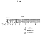
- Figure 1 shows a time configuration of a frame and subfields of a PDP.
- a single frame is divided into eight subfields SF1, SF2, SF3, SF4, SF5, SF6, SF7, SF8, and a number of sustain pulses are assigned to the subfields SF1 through SF8.
- the sustain pulse is a common signal inputted to an array of pixels, and the number of sustain pulses assigned to each of the subfields is weighted in proportion to the desired light emission time.
- the numbers of sustain pulses assigned to the subfields SF1 to SF8 are 1, 2, 4, 8, 16, 32, 64, 128, respectively.
- the eight subfields are represented by a subfield codeword which indicates whether the individual subfields in a frame indicate a light-emitting state.
- the subfield codeword is a sequential array of 8-bit binary data where each bit represents one of the subfields.
- the eight subfields in the above example can be represented as [10000001]. For each subfield, the binary number "1" indicates a light-emitting state whereas "0" indicates a non-light-emitting state.
- Each subfield includes a reset time, an address time and a sustain time.
- each pixel in the PDP is initialized.
- the address period the pixels that are to be put into a light-emitting state are selected.
- the selected pixels are controlled so that they emit light.
- the sustain pulse is generated in accordance with a weight assigned to each subfield.
- the duration of the period during which a selected pixel emits light is increased in proportion to the number of sustain pulses transmitted to the PDP during the sustaining period.
- the sustain pulse is a common signal transmitted to the pixels in a subfield.
- the sustain pulse is inputted to pixels that are linearly arranged to form a panel.
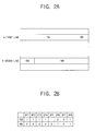
- Figure 2A illustrates a distribution of gradation levels per line
- Figure 2B illustrates a subfield codeword representing the respective subfields.
- a majority of the pixels in a first line in Figure 2A is expressed by gradation level [159], while a majority of the pixels in a second line is expressed by gradation level [160].
- the first subfield SF1 through the fifth subfield SF5 of gradation level [159] are in a light emitting state, whereas the sixth subfield SF6 is not in a light emitting state.
- the first through the fifth subfields SF1 to SF5 of the gradation level [160] are not in a light emitting state, while the sixth subfield SF6 is in a light emitting state.
- the load of the sustain pulse driving the first line is relatively heavy during the sustaining periods of the first to fifth subfields SF1 to SF5.
- the quantity of light emitted from each pixel decreases in proportion to the load of the sustain pulse, which increases in proportion to the number of pixels.
- the amount of the light emitted from the pixels in the sixth subfield SF6 is relatively high.
- Gradation level [159] differs from gradation level [160] by one gradation level. If the difference between the adjacent gradation levels is small, a viewer looking at the screen would hardly notice this difference. However, if these two adjacent gradation levels differ greatly in their brightness, the viewer may see an apparent borderline between pixels emitting light according to the two gradation levels.
- a display apparatus is characterised in that the usable subsets, for at least a part of the image being displayed, are limited such that subsets, representing adjacent brightness levels, differ by no more than a predetermined number of members.
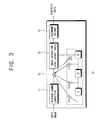
- FIG. 3 is a block diagram of a gradation converter 10 for use in a display apparatus according to a first embodiment of the invention.
- the gradation converter 10 converts an input image signal into a gradation levels selected from an image gradation level group and outputs the converted input image signal.
- the input image signal contains image data such as the brightness level of the pixels.
- the image gradation level group is a set of gradation levels in which the number of subfields which define different light-emitting states when compared with the corresponding subfields of adjacent gradation levels does not exceed a predetermined reference number. Such differences correspond to bit shifts in the corresponding subfield codewords.
- the image gradation level group comprises gradation levels where the total number of bit shifts between the subfield codewords of adjacent gradation levels is not more than the predetermined reference number.
- a frame is divided into subfields based on time.
- the frame is divided into eight subfields.
- the number of sustain pulses assigned to each of the subfields is limited to 2° to 2 n-1 .
- n is 8 since one frame is divided into eight subfields.
- the combination of 8-bit codewords results in the total number of representable gradation levels being 256.
- Figure 4 only shows gradation levels [0] to [33], but the total number of representable gradation levels is [0] to [255].
- the image gradation level group of Figure 4 is a set of representable gradation levels which have no more than two bits shifted when compared to the immediately preceding available gradation level.
- gradation level [15] differs from gradation level [14] by a single shifted bit.
- gradation levels [15] and [16] five bits are successively shifted from the first subfield to the fifth subfield. Therefore, gradation level [15], which has only one bit shifted from gradation level [14], is selected to be an available gradation level forming the image gradation level group, whereas gradation level [16], which has five bits shifted from gradation level [15], is deemed to be an unavailable gradation level.
- Figure 5 illustrates the subfield codewords of the available gradation levels forming the image gradation level group.
- the total number of bits shifted between adjacent available gradation levels is limited to a predetermined reference number, which is one or two.
- the image gradation level group sets a limit on the total number of bit shifts between adjacent gradation levels in order to prevent inaccurate display of gradation levels arising from the load of each line.
- the gradation converter 10 of Figure 3 comprises a reverse gamma corrector 11, a table defining an image gradation level group 12, a codeword driver 13 and an error diffusing part 14.
- the reverse gamma corrector 11 converts an input image signal on the basis of the following Equation (1).
- Y X 2.2 where "X" is the input video signal and "Y” is the output signal.
- the brightness levels of the input/output image signals can be represented as 6-bit integers.
- the output signal of the reverse gamma corrector 11 is added to the error of an adjacent pixel and inputted to the image gradation level group table 12.
- the image gradation level group table 12 stores the gradation levels that have been selected to form the image gradation level group, and converts the input video signal into one of the stored gradation levels. In other words, the image gradation level group table 12 converts the input video signal having the brightness level corresponding to gradation level [18] into an available gradation level [15].
- the converted gradation level [15] is inputted to the codeword driver 13, and the corresponding subfield codeword is transmitted to the display panel as information about the corresponding subfield.
- the subfield codeword is transmitted to the display panel as 8-bit data for each pixel during the address time, and accordingly, pixels are selected to emit light during the sustain period.
- the error diffusing part 14 partially maintains the average brightness level by diffusing the error generated due to the conversion between the gradation levels, that is, the error between the gradation level inputted to the image gradation level table 12 and the converted gradation level, to the adjacent pixel as follows.
- the diffused error is weighted according to the position of the pixel and added to the image information of the adjacent pixel.
- the error diffusing part 14 comprises a sustaining part arranged to sustain the error per line, pixel or clock, a multiplier for multiplying the error and weight and an adder adding the weighted error to the image information of the adjacent pixel.
- a dithering method may be used in place of the error diffusing method described above.
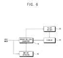
- FIG. 6 is a block diagram of a display apparatus according to a second embodiment of the invention.
- the display apparatus comprises a gradation level converter 10, a display 20, a pulse driver 30 and a motion detector 40.
- the gradation level converter 10 converts an input image into a gradation level and outputs the converted input image to the display 20.
- the pulse driver 30 supplies the sustain pulses assigned to each of the subfields to the display 20.
- the motion detector 40 detects whether the input image is a still picture.
- a number of detecting methods are suitable for use in the motion detector 40. For example, a motion estimation method that detects a motion vector between a former frame and a current frame per regular sized blocks or a motion detection method that tracks the shift of an image using the value of the pixels.
- the result of the detection method is outputted by the motion detector 40 to the gradation level converter 10. If the motion detector 40 does not detect any motion in the input image, the gradation level converter 10 converts the brightness level of the input image into a gradation level among a group of gradation levels that is suitable for a still image.
- the group of still image gradation levels comprises the same gradation levels as the image gradation level group described in relation to the first embodiment of the invention. However, if a gradation level previously deemed to be an 'unavailable gradation level' is redefined so that it is an available gradation level, the adjacent available gradation levels are no longer available gradation levels. In other words, the gradation levels in the image gradation level group are changed. For example, if the gradation level [4] in Figure 4 is set as an available gradation level, the adjacent gradation level [3] is no longer an available gradation level, and thus, available gradation levels [2] and [5] are now adjacent to the available gradation [4]. Accordingly, image gradation level groups can be formed with various combinations of the gradation levels within the set.
- the gradation level converter 10 converts the brightness level of the input image into a gradation level selected from a group of motion picture gradation levels.
- the motion picture gradation level group is a set of gradation levels configured to efficiently reduce false contours in the moving picture.
- a false contour generally occurs when a gradation difference between an area in which the image is moving and an adjacent area gradually accumulates and forms an afterimage around the area of motion.
- the image gradation level group is used in order to prevent the gradation level difference between the motion area and the adjacent area from accumulating gradually, thereby reducing false contours in the motion picture.
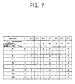
- Figure 7 shows the subfield codewords of an example motion picture gradation level group.
- Each of the codewords has one bit shifted when compared with the codewords of adjacent gradation levels.
- This motion picture gradation level group has a limited number of gradation levels to represent brightness, realizing decreased brightness while efficiently reducing the false contour of the motion picture.
- a still image gradation level group may include as many gradation levels as possible in order to enhance the image brightness.
- the still image gradation level group includes all the representable gradation levels in the gradation level table in Figure 4 as available gradation levels.
- the still image gradation level group has gradation levels having no more than a limited number of subfields which define a different light emitting state when compared with the corresponding subfields in adjacent gradation levels.
- the number of subfields whose corresponding light emitting states are different can be adjusted by a user as necessary, and preferably, but not necessarily, adjusted in consideration of the number of gradation levels applied to reproduce the brightness, as well as decreasing the gradation effect, in accordance with the load of the lines.
- Figure 7 illustrates an example of a motion picture gradation level group in which corresponding subfields of adjacent gradation levels differ by one bit shift.
- Figure 5 illustrates an example of a still image gradation level group in which corresponding subfields of adjacent gradation levels differ by no more than 2 bit shifts.
- the motion detector 40 determines whether the input image is a still image and outputs the result of this determination to the gradation level converter 10.
- the gradation level converter 10 converts the brightness level of the input image into a gradation level belonging to the motion picture gradation level group or the still picture gradation level group, depending on the output of the motion detector 40.
- the gradation level converter 10 outputs the converted input image to the display 20.
- the display 20 displays the input image in accordance with the subfield codeword outputted from the gradation level converter 10 and the sustain pulse outputted from the pulse driver 30. However, the sustain pulses outputted from the pulse driver 30 for each of the subfields are weighted.
- the number of the sustain pulses associated with each of the subfields can be adjusted according to an average picture level (APL) of a detectable input image by the gradation level converter 10.
- APL average picture level
- the gradation level converter 10 may balance the error between the input image and the converted gradation level by diffusing the error to the adjacent pixel based on the error diffusion method or the dithering method as described above.
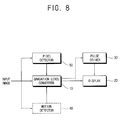
- FIG. 8 is a block diagram of a display apparatus according to a third embodiment of the present invention.
- the display apparatus comprises a gradation level converter 10, a display 20 and a pixel detector 50.
- the gradation level converter 10 converts input image data into a gradation level, and outputs it to the display 20.
- the pulse driver 30 transmits the sustain pulse weighted to each of the subfields to the display 20.
- the pixel detector 50 detects pixels sharing a common gradation level from the input image, and outputs its result to the gradation level converter 10. It is preferred, but not necessary, that the pixel detector 50 detects the pixels sharing the common gradation level for a given area or line which are driven by common sustain pulses.
- the gradation level converter 10 compares the brightness level of the input image with the common gradation level. The gradation level converter 10 then converts the brightness level of the input image into a gradation level, where the number of subfields that are in different light emitting states with respect to corresponding subfields in common gradation levels does not exceed a predetermined reference number of subfields.
- the configuration of the gradation levels changes, based on a reference gradation level that determines the gradation level group for a motion picture and the gradation level group for a still picture.
- a reference gradation level that determines the gradation level group for a motion picture
- the gradation level group for a still picture For example, in Figure 4, if gradation level [4] is set as the reference gradation level and adjacent gradation levels having no more than 2 bits shifted are selected to form a new gradation level group, it is obvious that the new gradation level group will be different from the gradation level group illustrated in Figure 5.
- the gradation level group of the gradation level converter 10 is flexibly configured as compared with the table shown in Figure 5. That is, the gradation level converter 10 converts the brightness level of the input image into one of the gradation levels among the newly formed gradation level group for the image, using the common gradation levels detected from the pixel detector 50.
- This change in the gradation levels may be applied across a whole frame. More preferably, the change can be limited to an area or line in which the pixel was detected.
- the display apparatus preferably further comprises the motion detector 40 detecting whether the input image is a moving picture or a still picture.
- the detected result of the motion detector 40 is outputted to the gradation level converter 10, and the gradation level converter 10 converts the input image into a gradation level according to the results output by the motion detector 40 and the pixel detector 50.
- the gradation level converter 10 converts the brightness level of the input image into one of the gradation levels in the group for a motion picture illustrated in Figure 7.
- the gradation level converter 10 applies the multi-gradation level group formed with the 'representable gradation levels' in Figure 4 to accurately express the brightness level of the input image.
- the gradation level converter 10 converts the brightness level of the input image into a gradation level so that the number of subfields which are in a different light emitting state with respect to the corresponding subfields in the common gradation level does not exceed the predetermined reference number of subfields.
- the load of a line will not cause a decrease in brightness, which is expressed by the gradation levels, and the load independent pixels of the image may be accurately displayed.
Landscapes
- Engineering & Computer Science (AREA)
- Physics & Mathematics (AREA)
- Computer Hardware Design (AREA)
- General Physics & Mathematics (AREA)
- Theoretical Computer Science (AREA)
- Plasma & Fusion (AREA)
- Power Engineering (AREA)
- Control Of Indicators Other Than Cathode Ray Tubes (AREA)
- Transforming Electric Information Into Light Information (AREA)
- Control Of Gas Discharge Display Tubes (AREA)
Applications Claiming Priority (2)
| Application Number | Priority Date | Filing Date | Title |
|---|---|---|---|
| KR1020040040987A KR20050116074A (ko) | 2004-06-04 | 2004-06-04 | 디스플레이장치 및 그 제어방법 |
| KR2004040987 | 2004-06-04 |
Publications (2)
| Publication Number | Publication Date |
|---|---|
| EP1603103A2 true EP1603103A2 (fr) | 2005-12-07 |
| EP1603103A3 EP1603103A3 (fr) | 2008-03-05 |
Family
ID=34940079
Family Applications (1)
| Application Number | Title | Priority Date | Filing Date |
|---|---|---|---|
| EP05104864A Withdrawn EP1603103A3 (fr) | 2004-06-04 | 2005-06-03 | Dispositif d'affichage |
Country Status (5)
| Country | Link |
|---|---|
| US (1) | US20060007251A1 (fr) |
| EP (1) | EP1603103A3 (fr) |
| JP (1) | JP2005346068A (fr) |
| KR (1) | KR20050116074A (fr) |
| CN (1) | CN1707591A (fr) |
Families Citing this family (8)
| Publication number | Priority date | Publication date | Assignee | Title |
|---|---|---|---|---|
| KR100627297B1 (ko) * | 2005-01-12 | 2006-09-25 | 삼성에스디아이 주식회사 | 플라즈마 표시 장치 및 그 화상 처리 방법 |
| KR20070047551A (ko) * | 2005-11-02 | 2007-05-07 | 엘지전자 주식회사 | 플라즈마 디스플레이 장치 |
| WO2007105447A1 (fr) * | 2006-02-23 | 2007-09-20 | Matsushita Electric Industrial Co., Ltd. | Procede de commande d'ecran a plasma et dispositif d'affichage a plasma |
| CN100578584C (zh) * | 2006-07-17 | 2010-01-06 | 中华映管股份有限公司 | 等离子显示面板的驱动装置及其驱动方法 |
| US20080079739A1 (en) * | 2006-09-29 | 2008-04-03 | Abhay Gupta | Graphics processor and method for controlling a display panel in self-refresh and low-response-time modes |
| GB2456164B (en) * | 2008-01-04 | 2010-01-27 | Sony Corp | Driving circuit for a liquid crystal display |
| EP2169941A1 (fr) * | 2008-09-26 | 2010-03-31 | Sony Corporation | Dispositif de conversion de gradation et procédé de conversion de gradation |
| KR102328841B1 (ko) * | 2014-12-24 | 2021-11-19 | 엘지디스플레이 주식회사 | 유기 발광 다이오드 표시장치와 그 구동 방법 |
Family Cites Families (4)
| Publication number | Priority date | Publication date | Assignee | Title |
|---|---|---|---|---|
| JPH0832903A (ja) * | 1994-07-18 | 1996-02-02 | Pioneer Electron Corp | プラズマディスプレイ装置 |
| JP4186579B2 (ja) * | 2002-10-11 | 2008-11-26 | 松下電器産業株式会社 | 画像表示方法および画像表示装置 |
| US7499062B2 (en) * | 2002-10-11 | 2009-03-03 | Panasonic Corporation | Image display method and image display apparatus for displaying a gradation by a subfield method |
| JP2005024717A (ja) * | 2003-06-30 | 2005-01-27 | Fujitsu Hitachi Plasma Display Ltd | ディスプレイ装置およびディスプレイの駆動方法 |
-
2004
- 2004-06-04 KR KR1020040040987A patent/KR20050116074A/ko not_active Withdrawn
-
2005
- 2005-05-30 JP JP2005157902A patent/JP2005346068A/ja active Pending
- 2005-06-03 EP EP05104864A patent/EP1603103A3/fr not_active Withdrawn
- 2005-06-03 CN CNA2005100732689A patent/CN1707591A/zh active Pending
- 2005-06-06 US US11/144,755 patent/US20060007251A1/en not_active Abandoned
Also Published As
| Publication number | Publication date |
|---|---|
| JP2005346068A (ja) | 2005-12-15 |
| EP1603103A3 (fr) | 2008-03-05 |
| CN1707591A (zh) | 2005-12-14 |
| KR20050116074A (ko) | 2005-12-09 |
| US20060007251A1 (en) | 2006-01-12 |
Similar Documents
| Publication | Publication Date | Title |
|---|---|---|
| KR100473514B1 (ko) | 서브프레임을 이용하여 그레이 스케일 디스플레이를실행하는 장치 및 방법 | |
| KR100781103B1 (ko) | 서브필드처리로 동작하는 디스플레이장치와 그러한 디스플레이장치에 영상을 표시하는 방법 | |
| KR101062198B1 (ko) | 디스플레이장치 및 그 제어방법 | |
| KR100428870B1 (ko) | 표시장치의 구동회로 | |
| AU738827B2 (en) | Dynamic image correction method and dynamic image correction circuit for display Device | |
| JP2003228319A (ja) | ディスプレイパネルの駆動方法 | |
| KR100924105B1 (ko) | 비디오 화상을 처리하기 위한 방법 및 장치 | |
| EP1577868A2 (fr) | Dispositif d'affichage | |
| EP1603103A2 (fr) | Dispositif d'affichage | |
| JPH0934403A (ja) | ディスプレイ装置の駆動回路 | |
| JP2005321775A (ja) | ディスプレー装置 | |
| CN101419775B (zh) | 等离子体显示装置及其控制方法 | |
| KR100493622B1 (ko) | 플라즈마 디스플레이 패널 | |
| KR100825355B1 (ko) | 화상 표시 장치 및 그 구동 방법 | |
| JPH11119730A (ja) | 映像表示装置 | |
| KR100825352B1 (ko) | 화상 표시 장치 및 화상 표시 장치의 구동 방법 | |
| JP3521591B2 (ja) | ディスプレイ装置の誤差拡散処理装置 | |
| EP1585093A2 (fr) | Méthode de commande d'un panneau d'affichage électroluminescent ou à plasma | |
| JP3206711B2 (ja) | ディスプレイ装置の駆動回路 | |
| JP2004233980A (ja) | 表示装置および表示方法 | |
| JPH11288240A (ja) | 表示装置の駆動方法及び回路 | |
| JP3525659B2 (ja) | 表示装置の駆動方法及び駆動回路 | |
| KR100612391B1 (ko) | 플라즈마 표시 장치 및 그 화상 처리 방법 | |
| JPH09244577A (ja) | ディスプレイ装置の誤差拡散処理装置 | |
| JPH09212126A (ja) | ディスプレイ装置の駆動回路 |
Legal Events
| Date | Code | Title | Description |
|---|---|---|---|
| PUAI | Public reference made under article 153(3) epc to a published international application that has entered the european phase |
Free format text: ORIGINAL CODE: 0009012 |
|
| AK | Designated contracting states |
Kind code of ref document: A2 Designated state(s): AT BE BG CH CY CZ DE DK EE ES FI FR GB GR HU IE IS IT LI LT LU MC NL PL PT RO SE SI SK TR |
|
| AX | Request for extension of the european patent |
Extension state: AL BA HR LV MK YU |
|
| PUAL | Search report despatched |
Free format text: ORIGINAL CODE: 0009013 |
|
| AK | Designated contracting states |
Kind code of ref document: A3 Designated state(s): AT BE BG CH CY CZ DE DK EE ES FI FR GB GR HU IE IS IT LI LT LU MC NL PL PT RO SE SI SK TR |
|
| AX | Request for extension of the european patent |
Extension state: AL BA HR LV MK YU |
|
| AKX | Designation fees paid | ||
| RBV | Designated contracting states (corrected) |
Designated state(s): AT BE |
|
| 17P | Request for examination filed |
Effective date: 20080905 |
|
| REG | Reference to a national code |
Ref country code: DE Ref legal event code: 8566 |
|
| STAA | Information on the status of an ep patent application or granted ep patent |
Free format text: STATUS: THE APPLICATION HAS BEEN WITHDRAWN |
|
| RBV | Designated contracting states (corrected) |
Designated state(s): GB NL |
|
| 18W | Application withdrawn |
Effective date: 20090205 |