EP1603207B1 - Gasgefülltes elektrisches Schaltentladungsrohr - Google Patents
Gasgefülltes elektrisches Schaltentladungsrohr Download PDFInfo
- Publication number
- EP1603207B1 EP1603207B1 EP05014971A EP05014971A EP1603207B1 EP 1603207 B1 EP1603207 B1 EP 1603207B1 EP 05014971 A EP05014971 A EP 05014971A EP 05014971 A EP05014971 A EP 05014971A EP 1603207 B1 EP1603207 B1 EP 1603207B1
- Authority
- EP
- European Patent Office
- Prior art keywords
- electric discharge
- cylindrical body
- electrode
- discharge tube
- gas filled
- Prior art date
- Legal status (The legal status is an assumption and is not a legal conclusion. Google has not performed a legal analysis and makes no representation as to the accuracy of the status listed.)
- Expired - Lifetime
Links
- 239000000919 ceramic Substances 0.000 claims description 35
- 239000011810 insulating material Substances 0.000 claims description 5
- 239000011295 pitch Substances 0.000 claims description 5
- 230000002093 peripheral effect Effects 0.000 claims description 4
- 229910000531 Co alloy Inorganic materials 0.000 claims description 3
- 229910001030 Iron–nickel alloy Inorganic materials 0.000 claims description 3
- 229910045601 alloy Inorganic materials 0.000 claims description 3
- 239000000956 alloy Substances 0.000 claims description 3
- KGWWEXORQXHJJQ-UHFFFAOYSA-N [Fe].[Co].[Ni] Chemical compound [Fe].[Co].[Ni] KGWWEXORQXHJJQ-UHFFFAOYSA-N 0.000 claims description 2
- 238000005476 soldering Methods 0.000 claims description 2
- OKTJSMMVPCPJKN-UHFFFAOYSA-N Carbon Chemical compound [C] OKTJSMMVPCPJKN-UHFFFAOYSA-N 0.000 description 40
- 229910052799 carbon Inorganic materials 0.000 description 40
- 239000007789 gas Substances 0.000 description 34
- 230000000052 comparative effect Effects 0.000 description 20
- 230000000694 effects Effects 0.000 description 16
- 239000011248 coating agent Substances 0.000 description 5
- XKRFYHLGVUSROY-UHFFFAOYSA-N Argon Chemical compound [Ar] XKRFYHLGVUSROY-UHFFFAOYSA-N 0.000 description 4
- 230000003213 activating effect Effects 0.000 description 4
- 239000000463 material Substances 0.000 description 3
- 229910052786 argon Inorganic materials 0.000 description 2
- 230000003247 decreasing effect Effects 0.000 description 2
- 230000002542 deteriorative effect Effects 0.000 description 2
- 239000011261 inert gas Substances 0.000 description 2
- 238000000034 method Methods 0.000 description 2
- 238000004544 sputter deposition Methods 0.000 description 2
- 239000003795 chemical substances by application Substances 0.000 description 1
- 239000012141 concentrate Substances 0.000 description 1
- 230000007423 decrease Effects 0.000 description 1
- 230000006866 deterioration Effects 0.000 description 1
- 230000005284 excitation Effects 0.000 description 1
- 230000002265 prevention Effects 0.000 description 1
- 230000000630 rising effect Effects 0.000 description 1
- 229910000679 solder Inorganic materials 0.000 description 1
- 230000007704 transition Effects 0.000 description 1
Images


Classifications
-
- H—ELECTRICITY
- H01—ELECTRIC ELEMENTS
- H01T—SPARK GAPS; OVERVOLTAGE ARRESTERS USING SPARK GAPS; SPARKING PLUGS; CORONA DEVICES; GENERATING IONS TO BE INTRODUCED INTO NON-ENCLOSED GASES
- H01T2/00—Spark gaps comprising auxiliary triggering means
- H01T2/02—Spark gaps comprising auxiliary triggering means comprising a trigger electrode or an auxiliary spark gap
-
- H—ELECTRICITY
- H01—ELECTRIC ELEMENTS
- H01J—ELECTRIC DISCHARGE TUBES OR DISCHARGE LAMPS
- H01J7/00—Details not provided for in the preceding groups and common to two or more basic types of discharge tubes or lamps
- H01J7/02—Selection of substances for gas fillings; Specified operating pressure or temperature
-
- H—ELECTRICITY
- H01—ELECTRIC ELEMENTS
- H01T—SPARK GAPS; OVERVOLTAGE ARRESTERS USING SPARK GAPS; SPARKING PLUGS; CORONA DEVICES; GENERATING IONS TO BE INTRODUCED INTO NON-ENCLOSED GASES
- H01T1/00—Details of spark gaps
- H01T1/20—Means for starting arc or facilitating ignition of spark gap
-
- H—ELECTRICITY
- H01—ELECTRIC ELEMENTS
- H01T—SPARK GAPS; OVERVOLTAGE ARRESTERS USING SPARK GAPS; SPARKING PLUGS; CORONA DEVICES; GENERATING IONS TO BE INTRODUCED INTO NON-ENCLOSED GASES
- H01T1/00—Details of spark gaps
- H01T1/20—Means for starting arc or facilitating ignition of spark gap
- H01T1/22—Means for starting arc or facilitating ignition of spark gap by the shape or the composition of the electrodes
-
- H—ELECTRICITY
- H01—ELECTRIC ELEMENTS
- H01T—SPARK GAPS; OVERVOLTAGE ARRESTERS USING SPARK GAPS; SPARKING PLUGS; CORONA DEVICES; GENERATING IONS TO BE INTRODUCED INTO NON-ENCLOSED GASES
- H01T4/00—Overvoltage arresters using spark gaps
- H01T4/10—Overvoltage arresters using spark gaps having a single gap or a plurality of gaps in parallel
- H01T4/12—Overvoltage arresters using spark gaps having a single gap or a plurality of gaps in parallel hermetically sealed
Definitions
- the present invention relates to a gas filled switching electric discharge tube. More particularly, the present invention relates to the structure of a gas filled switching electric discharge tube in which the voltage characteristic at the time of electric discharge is improved.
- the gas filled switching electric discharge tube includes: a cylindrical body made of an insulating material such as a ceramic; and a first and a second electrode for airtightly closing both ends of the cylindrical body, wherein an electric discharge gap is formed between the first electrode face of the first electrode and the second electrode face of the second electrode, and gas is filed into an airtightly closed space which is formed in the cylindrical body including the electric discharge gap. Due to the above structure, electric discharge is generated between the first electrode face and the second electrode face.
- Metalized faces are formed on both end faces, which come into contact with the electrodes, of the cylindrical body made of ceramic, and trigger wires are provided which come into contact with the metalized faces and extend on an inner wall face of the cylindrical body or, alternatively, trigger wires are provided which do not come into contact with the metalized faces but extend on the inner wall face of the cylindrical body.
- trigger wires are provided which do not come into contact with the metalized faces but extend on the inner wall face of the cylindrical body.
- Figs. 7 and 8 are views of the development of an inner wall face of the cylindrical body made of ceramic.
- the trigger wires 10a, 10b are extended from the metalized faces in the axial direction of the cylindrical body and arranged at regular intervals of 90°.
- the trigger wires are arranged at regular intervals of 90° on one metalized face 12 side and also arranged on the other metalized face 14 side alternately.
- the central trigger wires 10c are respectively arranged in the axial direction at regular intervals of 90° at the intermediate positions between the trigger wires 10a 10b which extend from the metalized faces.
- the trigger wires 10a, 10b the number of each of which is two, extending from the metalized faces in the axial direction are arranged close to each other.
- Other structural arrangements are the same as those of the case shown in Fig. 7 .
- EP0869529 discloses a discharge tube having sub-discharge trigger wires, according to the preamble of claim 1.
- a gas filled switching electric discharge tube comprising: a cylindrical body made of an insulating material; a first electrode and a second electrode for airtightly closing both ends of the cylindrical body; an electric discharge gap formed between a first electrode face of the first electrode and a second electrode face of the second electrode, an airtightly closed space formed in the cylindrical body being filled with gas; metalized faces formed on both end faces of the cylindrical body, the first and the second electrode being joined to the cylindrical body on both end faces of the cylindrical body; first trigger wires formed on an inner wall face of the cylindrical body, connected with the metalized faces; and second trigger wires formed on the inner wall face of the cylindrical body, not connected with the metalized faces, wherein the number of the second trigger wires is larger than the number of the first trigger wires, an interval of the electric discharge gap is made to be larger than a distance from the second trigger wires to the first or the second electrode face.
- a plurality of recess portions are formed on the first electrode face of the first electrode or the second electrode for airtightly closing both ends
- a gas filled switching electric discharge tube comprising: a cylindrical body made of insulating material; a first electrode and a second electrode for airtightly closing both ends of the cylindrical body; an electric discharge gap formed between a first electrode face of the first electrode and a second electrode face of the second electrode, an airtightly closed space formed in the cylindrical body being filled with gas; metalized faces formed on both end faces of the cylindrical body, the first and the second electrode being joined to the cylindrical body on both the end faces of the cylindrical body; first trigger wires formed on an inner wall face of the cylindrical body, connected with the metalized faces; and second trigger wires formed on the inner wall face of the cylindrical body, not connected with the metalized faces, wherein the number of the second trigger wires is larger than the number of the first trigger wires, and an interval of the electric discharge gap is made to be larger than a distance from the second trigger wires to the first or the second electrode face.
- the cylindrical body is a cylinder
- the first and the second electrode face are substantially circular and formed around the central axis of the cylindrical body
- the first and the second electrode face are arranged being symmetrically opposed to each other
- the first trigger wires extend from the metalized faces in the axial direction on the inner wall face of the cylindrical body, however, the first trigger wires do not reach a central portion of the cylindrical body
- the second trigger wires extend in the central portion of the cylindrical body in the axial direction.
- the first trigger wire extending from one metalized face on the inner wall face in the axial direction and the first trigger wire extending from the other metalized face on the inner wall face in the axial direction are arranged being formed into a pair at an interval of 180°.
- the pair of the first trigger wires are respectively composed of a plurality of trigger wires arranged close and parallel to each other, and the pair of the first trigger wires are respectively composed of 2 or 3 trigger wires arranged close and parallel to each other.
- the length of the first trigger wire in the axial direction is not more than 1/3 of the length of the cylindrical body in the axial direction.
- a plurality of the second trigger wires are arranged at substantially regular intervals between a pair of the first trigger wires which are arranged at an interval of 180°, and the length of the second trigger wire in the axial direction is not less than 1/2 of the length of the cylindrical body in the axial direction.
- the cylindrical body is a cylinder
- the first and the second electrode face are substantially circular and formed around the central axis of the cylindrical body
- the first and the second electrode face are arranged being symmetrically opposed to each other and the first trigger wires extend from the metalized face in the axial direction on the inner wall face of the cylindrical body.
- the first trigger wires do not reach a central portion of the cylindrical body
- the second trigger wires extend in the central portion of the cylindrical body in the axial direction
- a distance from the second trigger wire to the first or the second electrode face is the same as a distance from an outer circumference of the electrode face to an inner wall of the cylindrical body in the radial direction.
- An interval of the electric discharge gap is the same as a distance between an end portion of the first electrode face and an end portion of the second electrode face.
- a plurality of recess portions provided on the first or the second electrode face are respectively a hemispherical recess portion.
- the plurality of recess portions are uniformly arranged at regular pitches of 0.1-1.0 mm.
- the first and the second electrode face are arranged being symmetrically opposed to each other, central portions of the electrode faces are hollowed with respect to the peripheral portion, and the plurality of recess portions are formed in the hollow portion.
- the cylindrical body is made of ceramic, and the first and the second electrode are made of iron-nickel alloy such as 42-alloy or iron-nickel-cobalt alloy such as covar.
- the first and the second electrode are joined to the cylindrical body by means of soldering.
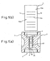
- Fig. 1(a) is a sectional view of a gas filled switching electric discharge tube of Embodiment 1 of the present invention
- Fig. 1(b) is a developed view of a cylindrical body, made of ceramic, used in Embodiment 1.
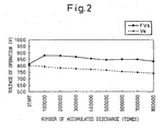
- Fig. 2 is a graph showing an effect of the gas filled switching electric discharge tube of Embodiment 1 of the present invention.
- the gas filled switching electric discharge tube of Embodiment 1 of the present invention includes: a cylindrical body made of an insulating material such as ceramic; and a first electrode 2 and a second electrode 3 for airtightly closing both end portions of the cylindrical body 1.
- the cylindrical body 1 is joined to the first electrode 2 and the second electrode 3 by the solder 4.
- Both end faces of the cylindrical body 1 made of ceramic are formed into the metalized faces 12, 14.
- the carbon trigger wires 10a, 10b on the sides of the metalized faces 12, 14 are arranged at an interval of 180° and extended from the metalized faces 12, 14 on the inner wall face of the cylindrical body 10, made of ceramic, in the axial direction, however, the lengths of the carbon trigger wires 10a, 10b are small.
- the carbon trigger wires 10c extend in the axial direction at the center on the inner wall face of the cylindrical body 1 made of ceramic.
- three carbon trigger wires 10c are arranged at regular intervals in every space between the trigger wires 10a and 10b which are respectively provided on the sides of the metalized faces 12, 14, that is, six carbon trigger wires 10c are arranged in total.
- the trigger wires 10a, 10b, 10c are arranged at regular intervals of about 45° in the circumferential direction. These trigger wires 10c arranged at the center of the inner wall do not come into contact with the metalized faces 12, 14.
- These trigger wires 10c arranged at the center of the inner wall are relatively longer than the carbon trigger wires 10a, 10b on the sides of the metalized faces 12, 14.
- the arrangements of the carbon trigger wires 10a, 10b, 10c of Embodiment 1 is the same as those shown in Fig. 9 .
- a plurality of carbon trigger wires (two carbon trigger wires) on each side of the metalized faces 12, 14 may be arranged close to each other.
- the electrodes 2, 3 are made of iron-nickel alloy such as 42 alloy or iron-nickel-cobalt-alloy such as covar. These electrodes 2, 3 are symmetrical to each other, and the electrode faces 20, 30 are formed to be substantially circular around the central axis of the cylindrical body 1 made of ceramic. These electrode faces 20, 30 are arranged to be symmetrically opposed to each other. Between these electrode faces 20, 30, the electric discharge gap 40 is formed. As is widely known, the inside of the cylindrical body 1 including the electric discharge gap 40 is filled with an inert gas such as argon gas. When a predetermined voltage is impressed between the electrodes 2, 3, an electric discharge occurs between the electrode faces 20, 30.
- an inert gas such as argon gas.
- the interval t of the electric discharge gap 40 which is measured at the end portions of the electrode faces 20, 30, is larger than the distance d which is a distance from the carbon trigger wire 10c at the central portion to the electrode face 20, 30, that is, a distance in the radial direction from the outer circumference of the electrode face 20, 30 to the inner wall of the cylindrical body made of ceramic.
- each electrode face 20, 30, which occupies the most of the area of the electrode is uniformly hollowed to the depth e with respect to the peripheral portion 22 of the electrode.
- this hollow portion 21 a plurality of hemispherical recess portions 23 are formed.
- the plurality of hemispherical recess portions 23 are arranged at regular pitches of 0.8 mm.
- the electrode faces 20, 30 having the plurality of hemispherical recess portions 23 are coated with an electric discharge activating coating agent.
- an electric discharge activating coating agent to be coated When a quantity of the electric discharge activating coating agent to be coated is appropriately adjusted, it is possible to extend the life of electric discharge.
- Table 2 shows a result of the dark place electric discharge life test of the electric discharge tube of Embodiment 1.
- Fig. 2 is a graph showing the result of the test.
- the abscissa represents the accumulated number of times of electric discharge (times), and the ordinate represents the operation voltage (V).
- FVs is an electric discharge starting voltage at the first time
- Vs is an average of the electric discharge starting voltage at the second time and after. In this test, it was possible to test 800,000 times.
- Table 2 Results of Embodiment 1 start 100000 200000 300000 400000 500000 600000 700000 800000 FVs 812 878 876 868 854 844 848 848 836 Vs 802 794 782 776 770 764 754 748 742
- Embodiment 1 is provided with all three requirements described as follows.
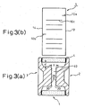
- Fig. 3(a) is a sectional view of a gas filled switching electric discharge tube of Embodiment 2 of the present invention
- Fig. 3(b) is a developed view of a cylindrical body, made of ceramic, used in Embodiment 2
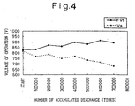
- Fig. 4 is a graph showing an effect of the gas filled switching electric discharge tube of Embodiment 2 of the present invention.
- Embodiment 2 does not satisfy (c) "Requirement for forming recess portions on an electrode face” but satisfies (a) "Requirement relating to the arrangement of carbon trigger wires” and (b) "Requirement relating to the size of an electric discharge gap". Accordingly, only different points of Embodiment 2 from the gas filled switching electric discharge tube of Embodiment 1 will be explained.
- Electrodes 2, 3 are symmetrical to each other, and the electrode faces 20, 30 are formed to be substantially circular around the central axis of the cylindrical body 1 made of ceramic. These electrode faces 20, 30 are arranged symmetrically opposed to each other. Between these electrode faces 20, 30, the electric discharge gap 40 is formed. As is widely known, the inside of the cylindrical body 1 including the electric discharge gap 40 is filled with an inert gas such as argon gas. The above points are the same as those of Embodiment 1.
- the interval t of the electric discharge gap 40 which is measured at the end portions of the electrode faces 20, 30, is larger than the distance d which is a distance in the radial direction from the outer circumference of the electrode face 20, 30 to the inner wall of the cylindrical body made of ceramic.
- Embodiment 2 a portion corresponding to the hollow portion 21, which is provided in Embodiments 1 to 3, is not provided. However, in this Embodiment 2, on the flat electrode faces 20, 30, there are provided grid-shaped protrusions 25.
- the electrode faces 20, 30 having the grid-shaped protrusions 25 are coated with an electric discharge activating coating agent.
- Table 5 shows a result of the dark place electric discharge life test of the electric discharge tube of Embodiment 2.
- Fig. 4 is a graph showing the result of the test. In this test of Embodiment 2, it was possible to test 700,000 times.
- Table 5 Results of Embodiment 2 start 100000 200000 300000 400000 500000 600000 700000 FVs 828 832 872 860 896 878 912 892 Vs 816 816 768 786 748 768 732 714 678
- Embodiment 2 does not satisfy (c) "Requirement for forming recess portions on an electrode face", but satisfies (a) "Requirement relating to the arrangement of carbon trigger wires” and (b) "Requirement relating to the size of an electric discharge gap”. Therefore, as can be seen in the test results, compared with the comparative example described later, even if the number of times of electric discharge is increased, Vs changes stably, and at the same time the life of electric discharge is extended, and further FVs characteristic is stabilized. In this way, the results are excellent. However, in Embodiment 2, both FVs and Vs are not stable, that is, Embodiment 2 is inferior to Embodiment 1 in the stability of the electric discharge voltage characteristic when comparison is made between Embodiments 1 and 2.
- Fig. 5(a) is a sectional view of a gas filled switching electric discharge tube Comparative Example
- Fig. 5(b) is a developed view of a cylindrical body made of ceramic used in this Comparative Example
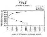
- Fig. 6 is a graph showing an effect of the gas filled switching electric discharge tube of the Comparative Example.
- the gas filled switching electric discharge tube of this Comparative Example satisfies only (c) "Requirement for forming recess portions on an electrode face", and does not satisfy (a) "Requirement relating to the arrangement of carbon trigger wires” and (b) "Requirement relating to the size of an electric discharge gap”.
- both end faces of the cylindrical body 1, made of ceramic are formed into the metalized faces 12, 14 and shown in Fig. 5(b) which is a developed view of the inner wall face of the cylindrical body 1 made of ceramic.
- the arrangement structure of the carbon trigger wires shown in Fig. 5(b) is the same as that shown in Fig. 7 . That is, the carbon trigger wires 10a, 10b on the sides of the metalized faces 12, 14 are alternately arranged at intervals of 90° one by one on the side of one metalized face 12 and on the side of the other metalized face 14.
- the carbon trigger wires 10c extending in the axial direction at the central portion on the inner wall face of the cylindrical body 10, made of ceramic, are arranged at regular intervals of 90° between the carbon trigger wires 10a, 10b on the sides of the metalized faces 12, 14, that is, the number of the carbon trigger wires 10c is four in total.
- the interval t of the electric discharge gap 40 which is measured at the end portions of the electrode faces 20, 30, is smaller than the distance d which is a distance from the carbon trigger wire 10c at the central portion to the electrode face 20, 30, that is, a distance in the radial direction from the outer circumference of the electrode face 20, 30 to the inner wall of the cylindrical body made of ceramic.
- each electrode face 20, 30, which occupies the most of the area of the electrode face is uniformly hollowed to the depth e with respect to the peripheral portion 22 of the electrode face.
- a plurality of hemispherical recess portions 23 are formed in the same manner as that of the above embodiments.
- the plurality of hemispherical recess portions 23 are arranged at regular pitches of 0.4 mm.
- the pitch in this Comparative Example is smaller than that of Embodiment 1.
- the depth of each hemispherical recess portion 23 in this Comparative Example is smaller than that of Embodiment 1.
- the electrode faces 20, 30 are coated with an electric discharge activating agent in the same manner as that of each embodiment described before.
- Table 6 shows a result of the dark place electric discharge life test of the electric discharge tube of Comparative Example.
- Fig. 6 is a graph showing the result of the test. In this test, it was possible to test only 400,000 times.
- Table 6 Results of Comparative Example start 100000 200000 300000 400000 FVs 833 924 948 960 972 Vs 828 784 721 664 640
- the Comparative Example satisfies only (c) "Requirement for forming recess portions on an electrode face” and does not satisfy (a) "Requirement relating to the arrangement of carbon trigger wires” and (b) "Requirement relating to the size of an electric discharge gap”. Therefore, as can be seen in the test results, when the number of times of electric discharge is increased, neither Vs nor FVs changes stably, and the life of electric discharge deteriorates and the electric discharge voltage characteristic is not stabilized.
- the carbon trigger wires are arranged as explained in Embodiments 1 and 2 in such a manner that the number of the carbon trigger wires on the sides of the metalized faces is decreased, and on the other hand, the number of the carbon trigger wires on the central side of the cylindrical body made of ceramic is increased.
- conductive sputtering material scatters from the electrodes due to the electric discharge energy and starts adhering in a belt shape to the central portion of the inner wall of the cylindrical body made of ceramic.
- this conductive sputtering material which has scattered in this way, extends to end portions of the carbon triggers on the sides of the metalized faces provided on both sides, Vs starts deteriorating and also the insulating resistance starts deteriorating in the life test.
- the number of the carbon trigger wires on the sides of the metalized faces is reduced to as small as possible.
- the present invention adopts an arrangement structure by which the highest effect can be provided for extending the life of electric discharge.
- the arrangement structure of the carbon trigger wires is not limited to the one shown in Fig. 9 .
- a plurality of carbon trigger wires are arranged close to each other on the sides of the metalized faces as shown in Fig. 10 , it is possible to provide the same effect.
- the interval of the electric discharge gap and the distance from the electrode face to the carbon trigger wire are restricted. That is, the interval of the electric discharge gap is extended with respect to the distance (interval) from the electrode face to the carbon trigger wire.
Landscapes
- Gas-Filled Discharge Tubes (AREA)
- Lasers (AREA)
- Testing Relating To Insulation (AREA)
- Ignition Installations For Internal Combustion Engines (AREA)
- Discharge Lamps And Accessories Thereof (AREA)
Claims (16)
- Gasgefüllte elektrische Schaltentladungsröhre, aufweisend:einen zylindrischen Körper (1) aus einem isolierenden Material; eine erste Elektrode (2) und eine zweite Elektrode (3) zum luftdichten Abschließen beider Enden des zylindrischen Körpers (1), so dass eine elektrische Entladungsstrecke (40) zwischen einer ersten Elektrodenfläche (20) der ersten Elektrode (2) und einer zweiten Elektrodenfläche (30) der zweiten Elektrode (3) ausgebildet ist, und einen in dem zylindrischen Körper (1) gebildeten luftdicht abgeschlossenen Raum, der mit Gas gefüllt ist;metallisierte Flächen (12, 14), die an beiden Endflächen des zylindrischen Körpers (1) ausgebildet sind, wobei die erste Elektrode (2) und die zweite Elektrode (3) an beiden Endflächen (12, 14) des zylindrischen Körpers (1) zu dem zylindrischen Körper (1) vereint werden;erste Zünddrähte (10a, 10b), die an einer inneren Wandfläche des zylindrischen Körpers (1) ausgebildet sind, und zwar mit den metallisierten Flächen (12, 14) verbunden; undzweite Zünddrähte (10c), die an der inneren Wandfläche des zylindrischen Körpers (1) ausgebildet sind, und zwar nicht mit den metallisierten Flächen (12, 14) verbunden,dadurch gekennzeichnet, dass:(i) die Anzahl der zweiten Zünddrähte (10c) höher als die Anzahl der ersten Zünddrähte (10a, 10b) ist; und(ii) ein Zwischenraum (t) der elektrischen Entladungsstrecke (40) größer ist als ein Abstand der zweiten Zünddrähte (10c) zu der ersten (20) oder der zweiten (30) Elektrodenfläche.
- Gasgefüllte elektrische Schaltentladungsröhre nach Anspruch 1, bei der eine Vielzahl von Aussparungsbereichen (23) an der ersten Elektrodenfläche (20) der ersten Elektrode (2) und/oder an der zweiten Elektrodenfläche (30) der zweiten Elektrode (3) ausgebildet sind.
- Gasgefüllte elektrische Schaltentladungsröhre nach Anspruch 1 oder Anspruch 2, bei welcher der zylindrische Körper (1) ein Zylinder ist, wobei die erste (20) und die zweite (30) Elektrodenfläche im Wesentlichen kreisförmig sind und um die Mittelachse des zylindrischen Körpers (1) herum ausgebildet sind, wobei die erste (20) und die zweite (30) Elektrodenfläche symmetrisch einander gegenüber angeordnet sind, sich die ersten Zünddrähte (10a, 10b) von den metallisierten Oberflächen (12, 14) in der axialen Richtung an der inneren Wandfläche des zylindrischen Körpers (1) erstrecken, aber die ersten Zünddrähte (10a, 10b) den Mittelbereich des zylindrischen Körpers (1) nicht erreichen, und sich die zweiten Zünddrähte (10c) in der axialen Richtung in dem Mittelbereich des zylindrischen Körpers (1) erstrecken.
- Gasgefüllte elektrische Schaltentladungsröhre nach Anspruch 3, bei der ein erster Zünddraht (10a, 10b) sich von einer metallisierten Fläche (12, 14) in der axialen Richtung an der inneren Wandfläche erstreckt und ein anderer erster Zünddraht (10a, 10b) sich von der anderen metallisierten Fläche (12, 14) in der axialen Richtung an der inneren Wandfläche erstreckt und beide so angeordnet sind, dass sie ein Paar mit einem Zwischenraum von 180° bilden.
- Gasgefüllte elektrische Schaltentladungsröhre nach Anspruch 4, bei der das Paar der ersten Zünddrähte (10a, 10b) jeweils aus einer Vielzahl von Zünddrahtadern besteht, die nah und parallel zueinander angeordnet sind.
- Gasgefüllte elektrische Schaltentladungsröhre nach Anspruch 4 oder 5, bei der das Paar der ersten Zünddrähte (10a, 10b) jeweils aus zwei oder drei Zünddrahtadern besteht, die nah und parallel zueinander angeordnet sind.
- Gasgefüllte elektrische Schaltentladungsröhre nach einem der Ansprüche 3 bis 6, bei der die Länge des ersten Zünddrahts (10a, 10b) in der axialen Richtung nicht mehr als ein Drittel der Länge des zylindrischen Körpers (1) in der axialen Richtung beträgt.
- Gasgefüllte elektrische Schaltentladungsröhre nach einem der Ansprüche 4 bis 7, bei der eine Vielzahl der zweiten Zünddrähte (10a) in im Wesentlichen regelmäßigen Intervallen zwischen einem Paar der ersten Zünddrähte (10a, 10b) angeordnet ist, welche mit einem Zwischenraum von 180° angeordnet sind.
- Gasgefüllte elektrische Schaltentladungsröhre nach einem der Ansprüche 3 bis 8, bei der die Länge des zweiten Zünddrahts (10c) in der axialen Richtung nicht weniger als eine Hälfte der Länge des zylindrischen Körpers (1) in der axialen Richtung beträgt.
- Gasgefüllte elektrische Schaltentladungsröhre nach Anspruch 9, bei der ein Abstand von dem zweiten Zünddraht (10c) zu der ersten (20) oder der zweiten (30) Elektrodenfläche der gleiche ist wie ein Abstand von einem Außenumfang der Elektrodenfläche (20, 30) zu einer Innenwand des zylindrischen Körpers (1) in der radialen Richtung.
- Gasgefüllte elektrische Schaltentladungsröhre nach Anspruch 10, bei der ein Zwischenraum (t) der elektrischen Entladungsstrecke (40) der gleiche ist wie ein Abstand zwischen einem Endbereich der ersten Elektrodenfläche (20) und einem Endbereich der zweiten Elektrodenfläche (30).
- Gasgefüllte elektrische Schaltentladungsröhre nach Anspruch 2, bei der die Vielzahl von Aussparungsbereichen halbkugelförmige Aussparungsbereiche (23) sind.
- Gasgefüllte elektrische Schaltentladungsröhre nach Anspruch 12, bei der die Vielzahl von Aussparungsbereichen (23) gleichmäßig in regelmäßigen Pitchabständen von 0,1 - 1,0 mm angeordnet sind.
- Gasgefüllte elektrische Schaltentladungsröhre nach einem der Ansprüche 2, 12 oder 13, bei der die erste (20) und die zweite (30) Elektrodenfläche symmetrisch einander gegenüberliegend angeordnet sind, wobei Mittelbereiche der Elektrodenflächen (20, 30) bezüglich des peripheren Bereichs ausgehöhlt sind und die Vielzahl von Aussparungsbereichen (23) in dem hohlen Teil ausgebildet ist.
- Gasgefüllte elektrische Schaltentladungsröhre nach einem der vorhergehenden Ansprüche, bei welcher der zylindrische Körper (1) aus Keramik besteht und die erste (2) und die zweite (3) Elektrode aus einer Eisen-Nickel-Legierung, wie etwa 42-Legierung, oder einer Eisen-Nickel-Cobalt-Legierung, wie etwa Covar, besteht.
- Gasgefüllte elektrische Schaltentladungsröhre nach einem der vorhergehenden Ansprüche, bei der die erste (2) und die zweite (3) Elektrode mittels Lötens mit dem zylindrischen Körper (1) verbunden sind.
Applications Claiming Priority (3)
| Application Number | Priority Date | Filing Date | Title |
|---|---|---|---|
| JP2001058864A JP3835990B2 (ja) | 2001-03-02 | 2001-03-02 | ガス封入スイッチング放電管 |
| JP2001058864 | 2001-03-02 | ||
| EP02251411A EP1237243B1 (de) | 2001-03-02 | 2002-02-28 | Gasgefüllte elektrische Entladungsschaltröhre |
Related Parent Applications (1)
| Application Number | Title | Priority Date | Filing Date |
|---|---|---|---|
| EP02251411A Division EP1237243B1 (de) | 2001-03-02 | 2002-02-28 | Gasgefüllte elektrische Entladungsschaltröhre |
Publications (3)
| Publication Number | Publication Date |
|---|---|
| EP1603207A2 EP1603207A2 (de) | 2005-12-07 |
| EP1603207A3 EP1603207A3 (de) | 2006-07-26 |
| EP1603207B1 true EP1603207B1 (de) | 2010-01-06 |
Family
ID=18918521
Family Applications (3)
| Application Number | Title | Priority Date | Filing Date |
|---|---|---|---|
| EP05014971A Expired - Lifetime EP1603207B1 (de) | 2001-03-02 | 2002-02-28 | Gasgefülltes elektrisches Schaltentladungsrohr |
| EP02251411A Expired - Lifetime EP1237243B1 (de) | 2001-03-02 | 2002-02-28 | Gasgefüllte elektrische Entladungsschaltröhre |
| EP05014972A Expired - Lifetime EP1594199B1 (de) | 2001-03-02 | 2002-02-28 | Gasgefülltes elektrisches Entladungsrohr |
Family Applications After (2)
| Application Number | Title | Priority Date | Filing Date |
|---|---|---|---|
| EP02251411A Expired - Lifetime EP1237243B1 (de) | 2001-03-02 | 2002-02-28 | Gasgefüllte elektrische Entladungsschaltröhre |
| EP05014972A Expired - Lifetime EP1594199B1 (de) | 2001-03-02 | 2002-02-28 | Gasgefülltes elektrisches Entladungsrohr |
Country Status (5)
| Country | Link |
|---|---|
| US (1) | US6617804B2 (de) |
| EP (3) | EP1603207B1 (de) |
| JP (1) | JP3835990B2 (de) |
| KR (1) | KR100854009B1 (de) |
| DE (3) | DE60237853D1 (de) |
Families Citing this family (12)
| Publication number | Priority date | Publication date | Assignee | Title |
|---|---|---|---|---|
| JP4410527B2 (ja) * | 2003-10-06 | 2010-02-03 | 新光電気工業株式会社 | 放電管 |
| JP2006012519A (ja) * | 2004-06-24 | 2006-01-12 | Shinko Electric Ind Co Ltd | 表面実装用放電管 |
| DE102005036265A1 (de) * | 2005-08-02 | 2007-02-08 | Epcos Ag | Funkenstrecke |
| DE112006002464T5 (de) | 2005-09-14 | 2008-07-24 | Littelfuse, Inc., Des Plaines | Gasgefüllter Überspannungsableiter, aktivierende Verbindung, Zündstreifen und Herstellungsverfahren dafür |
| JP2008251389A (ja) * | 2007-03-30 | 2008-10-16 | Okaya Electric Ind Co Ltd | 放電管 |
| ES2387340T3 (es) * | 2007-12-21 | 2012-09-20 | Bae Systems Plc | Conmutador de alta tensión |
| EP2073326A1 (de) * | 2007-12-21 | 2009-06-24 | BAE Systems plc | Hochspannungsschalter |
| RU2474910C1 (ru) * | 2011-07-01 | 2013-02-10 | Учреждение Российской академии наук Физический институт им. П.Н. Лебедева РАН (ФИАН) | Получение однородности газового разряда |
| CN105225905B (zh) * | 2015-09-10 | 2017-03-08 | 安徽华夏显示技术股份有限公司 | 一种放电频率可控型放电管及其制造方法 |
| CN107706074B (zh) * | 2017-09-25 | 2024-02-09 | 深圳市槟城电子股份有限公司 | 气体放电管 |
| US11769991B2 (en) * | 2021-10-05 | 2023-09-26 | Unison Industries, Llc | Glow discharge tube with a set of electrodes within a gas-sealed envelope |
| JP2024081879A (ja) * | 2022-12-07 | 2024-06-19 | ウシオ電機株式会社 | 閃光照射装置、閃光放電ランプ |
Family Cites Families (9)
| Publication number | Priority date | Publication date | Assignee | Title |
|---|---|---|---|---|
| JPS607183U (ja) * | 1983-06-25 | 1985-01-18 | 株式会社サンコ−シャ | 過電圧保護素子 |
| JPS61281489A (ja) * | 1985-06-06 | 1986-12-11 | 株式会社サンコ−シャ | 避雷器 |
| JPH0362486A (ja) * | 1989-07-28 | 1991-03-18 | Shinko Electric Ind Co Ltd | 高電圧スイッチ素子用ガス入り放電管 |
| JPH0785840A (ja) * | 1993-09-20 | 1995-03-31 | Yazaki Corp | ガス入り放電管 |
| DE19632417C1 (de) * | 1996-08-05 | 1998-05-07 | Siemens Ag | Gasgefüllter Überspannungsableiter mit Elektroden-Aktivierungsmasse |
| JPH10335042A (ja) | 1997-03-31 | 1998-12-18 | Shinko Electric Ind Co Ltd | 放電管 |
| US6194820B1 (en) * | 1998-02-20 | 2001-02-27 | Shinko Electric Industries Co., Ltd. | Discharge tube having switching spark gap |
| JP3995339B2 (ja) * | 1998-06-10 | 2007-10-24 | 新光電気工業株式会社 | 放電管 |
| DE19920043A1 (de) * | 1999-04-23 | 2000-10-26 | Epcos Ag | Gasgefüllter Überspannungsableiter mit einer aus mehreren Komponenten bestehenden Aktivierungsmasse |
-
2001
- 2001-03-02 JP JP2001058864A patent/JP3835990B2/ja not_active Expired - Fee Related
-
2002
- 2002-02-26 US US10/083,458 patent/US6617804B2/en not_active Expired - Lifetime
- 2002-02-28 DE DE60237853T patent/DE60237853D1/de not_active Expired - Lifetime
- 2002-02-28 KR KR1020020010907A patent/KR100854009B1/ko not_active Expired - Fee Related
- 2002-02-28 DE DE60235048T patent/DE60235048D1/de not_active Expired - Lifetime
- 2002-02-28 EP EP05014971A patent/EP1603207B1/de not_active Expired - Lifetime
- 2002-02-28 EP EP02251411A patent/EP1237243B1/de not_active Expired - Lifetime
- 2002-02-28 DE DE60215876T patent/DE60215876T2/de not_active Expired - Lifetime
- 2002-02-28 EP EP05014972A patent/EP1594199B1/de not_active Expired - Lifetime
Also Published As
| Publication number | Publication date |
|---|---|
| EP1603207A3 (de) | 2006-07-26 |
| JP2002260809A (ja) | 2002-09-13 |
| DE60215876T2 (de) | 2007-03-01 |
| KR100854009B1 (ko) | 2008-08-26 |
| EP1237243A2 (de) | 2002-09-04 |
| EP1594199A2 (de) | 2005-11-09 |
| DE60215876D1 (de) | 2006-12-21 |
| US6617804B2 (en) | 2003-09-09 |
| EP1237243B1 (de) | 2006-11-08 |
| EP1594199B1 (de) | 2010-09-29 |
| JP3835990B2 (ja) | 2006-10-18 |
| EP1237243A3 (de) | 2003-09-17 |
| DE60237853D1 (de) | 2010-11-11 |
| US20020171362A1 (en) | 2002-11-21 |
| KR20020070876A (ko) | 2002-09-11 |
| DE60235048D1 (de) | 2010-02-25 |
| EP1603207A2 (de) | 2005-12-07 |
| EP1594199A3 (de) | 2007-02-21 |
Similar Documents
| Publication | Publication Date | Title |
|---|---|---|
| EP1603207B1 (de) | Gasgefülltes elektrisches Schaltentladungsrohr | |
| US4433354A (en) | Gas-discharge surge arrester | |
| EP2214273B1 (de) | Zündkerze | |
| KR960000922B1 (ko) | 가스방전 서어지 어레스터 | |
| JPH0831352B2 (ja) | スパークプラグ | |
| US4493004A (en) | Surge arrester with a gas-filled housing | |
| US4578733A (en) | Surge voltage arrester | |
| JP2001516943A (ja) | ガス充填形放電路 | |
| EP1239562B1 (de) | Gasgefüllte elektrische Entladungsschaltröhre | |
| JPS62256394A (ja) | 避雷器 | |
| US5142194A (en) | Spark gap component of particular spacing mounted within a shield | |
| US4797778A (en) | Gas discharge path | |
| CA1189137A (en) | Gas-discharge overvoltage arrester with concentrically surrounding socket | |
| EP1115187B1 (de) | Überspannungsableiter mit drei Elektroden | |
| US4410831A (en) | Overvoltage protecting element | |
| EP0869529B1 (de) | Entladungsröhre | |
| US3885202A (en) | Excess voltage arresters | |
| KR100257585B1 (ko) | 갭형 서어지흡수기 | |
| JP2004127832A (ja) | ガスアレスタ | |
| EP3419124B1 (de) | Zündkerze | |
| US5473220A (en) | Discharge tube | |
| JP3430591B2 (ja) | サージアブソーバ | |
| JPH113764A (ja) | 放電管型サージアブソーバ | |
| JPH0658592U (ja) | 放電管 | |
| JPH04155792A (ja) | 高電圧スイッチ素子用ガス入り放電管及びこれを用いた点火プラグ |
Legal Events
| Date | Code | Title | Description |
|---|---|---|---|
| PUAI | Public reference made under article 153(3) epc to a published international application that has entered the european phase |
Free format text: ORIGINAL CODE: 0009012 |
|
| AC | Divisional application: reference to earlier application |
Ref document number: 1237243 Country of ref document: EP Kind code of ref document: P |
|
| AK | Designated contracting states |
Kind code of ref document: A2 Designated state(s): DE FR GB IT |
|
| PUAL | Search report despatched |
Free format text: ORIGINAL CODE: 0009013 |
|
| AK | Designated contracting states |
Kind code of ref document: A3 Designated state(s): DE FR GB IT |
|
| RIC1 | Information provided on ipc code assigned before grant |
Ipc: H01T 4/12 20060101ALI20060622BHEP Ipc: H01T 1/22 20060101AFI20051011BHEP Ipc: H01T 1/24 20060101ALI20060622BHEP Ipc: H01T 2/02 20060101ALI20060622BHEP |
|
| 17P | Request for examination filed |
Effective date: 20070115 |
|
| AKX | Designation fees paid |
Designated state(s): DE FR GB IT |
|
| GRAP | Despatch of communication of intention to grant a patent |
Free format text: ORIGINAL CODE: EPIDOSNIGR1 |
|
| GRAS | Grant fee paid |
Free format text: ORIGINAL CODE: EPIDOSNIGR3 |
|
| GRAA | (expected) grant |
Free format text: ORIGINAL CODE: 0009210 |
|
| AC | Divisional application: reference to earlier application |
Ref document number: 1237243 Country of ref document: EP Kind code of ref document: P |
|
| AK | Designated contracting states |
Kind code of ref document: B1 Designated state(s): DE FR GB IT |
|
| REG | Reference to a national code |
Ref country code: GB Ref legal event code: FG4D |
|
| REF | Corresponds to: |
Ref document number: 60235048 Country of ref document: DE Date of ref document: 20100225 Kind code of ref document: P |
|
| RAP2 | Party data changed (patent owner data changed or rights of a patent transferred) |
Owner name: SHINKO ELECTRIC INDUSTRIES CO., LTD. |
|
| REG | Reference to a national code |
Ref country code: FR Ref legal event code: CA |
|
| PLBE | No opposition filed within time limit |
Free format text: ORIGINAL CODE: 0009261 |
|
| STAA | Information on the status of an ep patent application or granted ep patent |
Free format text: STATUS: NO OPPOSITION FILED WITHIN TIME LIMIT |
|
| 26N | No opposition filed |
Effective date: 20101007 |
|
| REG | Reference to a national code |
Ref country code: FR Ref legal event code: PLFP Year of fee payment: 14 |
|
| PGFP | Annual fee paid to national office [announced via postgrant information from national office to epo] |
Ref country code: IT Payment date: 20150218 Year of fee payment: 14 Ref country code: DE Payment date: 20150224 Year of fee payment: 14 |
|
| PGFP | Annual fee paid to national office [announced via postgrant information from national office to epo] |
Ref country code: FR Payment date: 20150210 Year of fee payment: 14 Ref country code: GB Payment date: 20150225 Year of fee payment: 14 |
|
| REG | Reference to a national code |
Ref country code: DE Ref legal event code: R119 Ref document number: 60235048 Country of ref document: DE |
|
| GBPC | Gb: european patent ceased through non-payment of renewal fee |
Effective date: 20160228 |
|
| REG | Reference to a national code |
Ref country code: FR Ref legal event code: ST Effective date: 20161028 |
|
| PG25 | Lapsed in a contracting state [announced via postgrant information from national office to epo] |
Ref country code: IT Free format text: LAPSE BECAUSE OF NON-PAYMENT OF DUE FEES Effective date: 20160228 |
|
| PG25 | Lapsed in a contracting state [announced via postgrant information from national office to epo] |
Ref country code: FR Free format text: LAPSE BECAUSE OF NON-PAYMENT OF DUE FEES Effective date: 20160229 Ref country code: DE Free format text: LAPSE BECAUSE OF NON-PAYMENT OF DUE FEES Effective date: 20160901 Ref country code: GB Free format text: LAPSE BECAUSE OF NON-PAYMENT OF DUE FEES Effective date: 20160228 |