EP1603370A1 - Unité d'éclairage de zone - Google Patents
Unité d'éclairage de zone Download PDFInfo
- Publication number
- EP1603370A1 EP1603370A1 EP05011842A EP05011842A EP1603370A1 EP 1603370 A1 EP1603370 A1 EP 1603370A1 EP 05011842 A EP05011842 A EP 05011842A EP 05011842 A EP05011842 A EP 05011842A EP 1603370 A1 EP1603370 A1 EP 1603370A1
- Authority
- EP
- European Patent Office
- Prior art keywords
- light
- percent
- light scattering
- lighting unit
- exit surface
- Prior art date
- Legal status (The legal status is an assumption and is not a legal conclusion. Google has not performed a legal analysis and makes no representation as to the accuracy of the status listed.)
- Withdrawn
Links
Images

Classifications
-
- H—ELECTRICITY
- H05—ELECTRIC TECHNIQUES NOT OTHERWISE PROVIDED FOR
- H05B—ELECTRIC HEATING; ELECTRIC LIGHT SOURCES NOT OTHERWISE PROVIDED FOR; CIRCUIT ARRANGEMENTS FOR ELECTRIC LIGHT SOURCES, IN GENERAL
- H05B33/00—Electroluminescent light sources
- H05B33/12—Light sources with substantially two-dimensional [2D] radiating surfaces
- H05B33/22—Light sources with substantially two-dimensional [2D] radiating surfaces characterised by the chemical or physical composition or the arrangement of auxiliary dielectric or reflective layers
-
- G—PHYSICS
- G02—OPTICS
- G02F—OPTICAL DEVICES OR ARRANGEMENTS FOR THE CONTROL OF LIGHT BY MODIFICATION OF THE OPTICAL PROPERTIES OF THE MEDIA OF THE ELEMENTS INVOLVED THEREIN; NON-LINEAR OPTICS; FREQUENCY-CHANGING OF LIGHT; OPTICAL LOGIC ELEMENTS; OPTICAL ANALOGUE/DIGITAL CONVERTERS
- G02F1/00—Devices or arrangements for the control of the intensity, colour, phase, polarisation or direction of light arriving from an independent light source, e.g. switching, gating or modulating; Non-linear optics
- G02F1/01—Devices or arrangements for the control of the intensity, colour, phase, polarisation or direction of light arriving from an independent light source, e.g. switching, gating or modulating; Non-linear optics for the control of the intensity, phase, polarisation or colour
- G02F1/13—Devices or arrangements for the control of the intensity, colour, phase, polarisation or direction of light arriving from an independent light source, e.g. switching, gating or modulating; Non-linear optics for the control of the intensity, phase, polarisation or colour based on liquid crystals, e.g. single liquid crystal display cells
- G02F1/133—Constructional arrangements; Operation of liquid crystal cells; Circuit arrangements
- G02F1/1333—Constructional arrangements; Manufacturing methods
- G02F1/1335—Structural association of cells with optical devices, e.g. polarisers or reflectors
- G02F1/1336—Illuminating devices
- G02F1/133602—Direct backlight
- G02F1/133606—Direct backlight including a specially adapted diffusing, scattering or light controlling members
- G02F1/133607—Direct backlight including a specially adapted diffusing, scattering or light controlling members the light controlling member including light directing or refracting elements, e.g. prisms or lenses
Definitions
- the present invention relates to an area lighting unit which is provided with an electroluminescent device.
- Japanese unexamined patent publications No. 8-83688, No. 2000-277266 and No. 2003-109747 disclose that an area lighting unit, which emits light in planar form from an electroluminescent device, or EL device, as a source of luminescence, is, for example, used as a backlight of the liquid crystal display.
- the publication No. 8-83688 discloses that the unit is provided with a light scattering portion outside the light exit surface of the organic EL device.
- the light scattering portion is formed by adhering a lens sheet on the transparent substrate for mounting the organic EL device, by frosting the surface of the transparent substrate, or by dispersing opaque particles within the transparent substrate.
- the light scattering portion is to prevent a cathode (or mirror electrode), which is a part of the organic EL device, from being viewed as a mirror surface by reflecting light which enters from the outside.
- the publication No. 2000-277266 discloses that the unit is provided with a light converging layer on the light exit surface of the transparent substrate which mounts thereon the organic EL device.
- the light converging layer includes a plurality of microscopic parallel prisms.
- the light converging layer is to converge light which exits from the organic EL device for enhancing directivity toward the front of the device.
- the units disclosed in the publications No. 8-83688 and No. 2000-277266 are insufficient to enhance the front brightness of light emitted from the organic EL device toward the front of the area lighting unit, and do not sufficiently use light emitted from the organic EL device. Therefore, a large amount of electrical power consumption is required for retaining higher front brightness.
- the publication No. 2003-109747 discloses the device that a light diffusing portion is provided on the transparent substrate which mounts thereon the organic EL device and also discloses that a light converging portion is provided on a light exit side of the light diffusing portion.
- the light scattering portion is formed by dispersing a light scattering material, which has a refractive index different from a transparent sheet, within the transparent sheet, or by dispersing the light scattering material, which has a refractive index different from the transparent substrate, within the transparent substrate.
- the light converging portion includes a lens having a shape for converging light which exits from the light diffusing portion.
- the light scattering portion is to prevent light emitted from the organic EL device from total reflection at the interface between the surface of the transparent substrate and air.
- the light converging portion is to enhance front brightness by converging light which exits from the light diffusing portion.
- the unit disclosed in the publication No. 2003-109747 is provided with a light diffusing portion and a light converging portion that utilizes light emitted from the organic EL device more efficiently than the units disclosed in the publications No. 8-83688 and No. 2000-277266 and requires less power for ensuring high front brightness than the units disclosed in the publications No. 8-83688 and No. 2000-277266.
- the publication No. 2003-109747 just discloses the light converging portion formed by a lens having a shape which is designed for converging light which exits from the light diffusing portion.
- the specific structure of the light converging portion appropriate for improving the utilization rate of light emitted from the organic EL device is not disclosed at all.
- the present invention addresses an area lighting unit which has a high utilization rate and front brightness of light emitted from the EL device. It is noted that the language "front brightness” means the brightness of the normal direction to the light exit surface of an EL device.
- an area lighting unit has an electroluminescent device, a light scattering portion and a light converging portion.
- the light scattering portion is provided on a side of a light exit surface of the electroluminescent device.
- the light converging portion is provided on a side of a light exit surface of the light scattering portion.
- the light converging portion includes first and second optical sheets which are layered, each having a planar light incidence portion through which light enters and a light exit portion through which the light exits.
- the light exit portion of each optical sheet forms a plurality of prismatic protrusions arranged in a parallel relation to each other. Each protrusion has a vertex angle of 90 degrees to 105 degrees.
- the first and second optical sheets each are so arranged that the light incidence portion is oriented to the electroluminescent device and a direction in which the protrusions of the first optical sheet are arranged is perpendicular to a direction in which the protrusions of the second optical sheet are arranged.
- a liquid crystal display 11 includes a liquid crystal panel 12 and a backlight 13, or area lighting unit, arranged on the back side (the surface opposite to the display surface) of the liquid crystal panel 12.
- the backlight 13 includes a transparent substrate 14, an organic electroluminescent device 15 provided on the light incidence surface 141 of the transparent substrate 14, a light scattering film 17, or a light scattering portion, adhered to the light exit surface 142 of the transparent substrate 14 through an adhesive layer 16, and two prism sheets 18, 19, or optical sheets, provided on the light exit surface 171 of the light scattering film 17.
- the prism sheets 18, 19 serve as a light converging portion in this embodiment.
- the light scattering film 17 is contiguous to the prism sheet 18.
- the prism sheet 18 is contiguous to the prism sheet 19.
- the transparent substrate 14, the adhesive layer 16, the light scattering film 17 and the prism sheets 18, 19 are made of a material having a relatively high light transmittance.
- the organic electroluminescent device 15, or the organic EL device includes a first electrode 20, an organic electroluminescent layer 21, or organic EL layer, and a second electrode 22, which are layered on the light incidence surface 141 of the transparent substrate 14 in this order.
- the organic EL device 15 is coated with a protection layer (not shown) which prevents penetration of moisture and oxygen to avoid exposing the organic EL layer 21 to ambient air.
- the first electrode 20 is made of a transparent and electrically conductive material, such as indium tin oxide.
- the organic EL layer 21 forms a three-layer structure including a hole transport layer, a luminescent layer and an electron injection layer in the order from the side of the first electrode 20, or forms a four-layer structure including a hole transport layer, a luminescent layer, an electron transport layer and an electron injection layer.
- the organic EL layer 21 is formed to emit white light.
- the second electrode 22 is made of metal having light reflectivity, such as aluminum.
- the second electrode 22 is a cathode.
- the first electrode 20 is an anode. When voltage is applied between the first electrode 20 and the second electrode 22, the organic EL layer 21 emits white light.
- the light exit surface 171 of the light scattering film 17 is roughened to form a rough surface which can scatter light.
- the surface roughness of the light exit surface 171 is set so that Ra (arithmetic mean roughness) ranges from 0.6 ⁇ m to 1 ⁇ m.
- the light scattering film 17 is adhered to the transparent substrate 14 through the adhesive layer 16 so that the light incidence surface 172, which is opposite to the rough light exit surface 171, faces the light exit surface 142 of the transparent substrate 14.
- the material of the adhesive layer 16 will be selected so that the adhesive layer 16 has a refractive index close to that of the transparent substrate 14 and that of the light scattering film 17.
- a plurality of prismatic protrusions 23, 24 are respectively formed on one side of prism sheets 18, 19 and arranged in parallel rows.
- the parallel arranged protrusions 23 form the light exit portion 181 of the prism sheet 18.
- the parallel arranged protrusions 24 form the light exit surface 191 of the prism sheet 19.
- the opposite sides of the light exit portions 181, 191 of the prism sheets 18, 19 are planar light incidence portions 182, 192, as shown in FIG. 1A.
- the light incidence portion 182 of the prism sheet 18 faces the light exit surface 171 of the light scattering film 17.
- the light incidence portion 192 of the prism sheet 19 faces the light exit portion 181 of the prism sheet 18.
- the light incidence portions 182, 192 are oriented to the organic EL device 15.
- the protrusions 23 of the prism sheet 18 each form a pair of planar inclined surfaces 231, 232.
- the connections 233 between the inclined surfaces 231, 232 (which are located away from the light incidence portion 182) are included in the same plane P1, and each protrusion 23 has the same height.
- the hypothetical plane P1 is in a parallel relation to the planar light incidence portion 182 in this embodiment.
- the vertex angles ⁇ 1 between the inclined surfaces 231, 232 (the vertex angles at the connections 233) are the same, and each protrusion 23 has a cross-section of the same shape and size isosceles triangle which is taken by the plane perpendicular to the longitudinal direction (indicated by the arrow Q1 in FIG. 1 B).
- the angle ⁇ 11 which the plane P1 makes with the inclined surface 231 is substantially equal to the angle ⁇ 12 which the plane P1 makes with the surface 232.
- the protrusions 24 of the prism sheet 19 each form a pair of planar inclined surfaces 241, 242.
- the connections 243 between the inclined surfaces 241, 242 (which are located away from the light incidence portion 192) are included in the same plane P2, and each protrusion 24 has the same height.
- the hypothetical plane P2 is in a parallel relation to the planar light incidence portion 192 in this embodiment.
- the vertex angles ⁇ 2 between the inclined surfaces 241, 242 (the vertex angles at the connections 243) are the same, and each protrusion 24 has a cross-section of the same shape and size isosceles triangle which is taken by the plane perpendicular to the longitudinal direction (indicated by the arrow Q2 in FIG. 1 B).
- the angle ⁇ 21 which the plane P2 makes with the inclined surface 241 is substantially equal to the angle ⁇ 22 which the plane P2 makes with the surface 242.
- the vertex angle ⁇ 1 of the prismatic protrusions 23 are substantially equal to the vertex angle ⁇ 2 of the prismatic protrusions 24.
- the cross-section of the protrusions 23 of the prism sheet 18 has the same shape and size as that of the protrusions 24 of the prism sheet 19.
- the pitch of the protrusions 23 is the same as the pitch of the protrusions 24.
- the prism sheet 18 is provided on the light exit surface 171 of the light scattering film 17 so that the light incidence portion 182 contacts and faces the light exit surface 171 of the light scattering film 17.
- the prism sheet 19 is provided on the light exit portion 181 of the prism sheet 18 so that the light incidence portion 192 contacts and faces the light exit portion 181 of the prism sheet 18.
- a pair of the prism sheets 18, 19 is so arranged that the direction in which the protrusions 23 of one prism sheet 18 extend is perpendicular to the direction in which the protrusions 24 of the other prism sheet 19 extend. Accordingly, the direction in which the protrusions 23 are arranged in the prism sheet 18 (which is indicated by the arrow S in FIG. 1 B) is perpendicular to the direction in which the protrusions 24 are arranged in the prism sheet 19 (which is indicated by the arrow S2 in FIG. 1 B).
- Light emitted from the organic EL device 15 passes through the transparent substrate 14 and the adhesive layer 16 and then enters into the light scattering film 17 through the light incidence surface 172.
- the refractive index of the adhesive layer 16 When the refractive index of the adhesive layer 16 is set close to the refractive indices of the transparent substrate 14 and the light scattering film 17, light emitted from the organic EL device 15 enters into the light scattering film 17 with little total reflection at the interface between the transparent substrate 14 and the adhesive layer 16 and at the interface between the adhesive layer 16 and the light scattering film 17. Thus, the utilization rate of light is improved.
- Light which has exited from the light scattering film 17 enters into the prism sheet 18 through the light incidence portion 182 of the prism sheet 18. Since the light exit surface 171 of the light scattering film 17 is roughened, the light exit surface 171 does not closely contact the light incidence portion 182 of the prism sheet 18, and air occupies a gap between the light exit surface 171 and the light incidence portion 182. Since the refractive index of air is smaller than that of the prism sheet 18, light which has entered into the prism sheet 18 through the light incidence portion 182 is refracted to come close to the normal direction to the light incidence portion 182 at the interface between air and the light incidence portion 182.
- the remainder of light which has reached the light exit portion 181 is totally reflected on the inclined surfaces 231, 232. Totally reflected light is reflected on the rough light exit surface 171 of the light scattering film 17 or the second electrode 22 of the organic EL device 15, and then enters into the prism sheet 18 again. At the same time, light is refracted on the rough light exit surface 171, with the result that more light can exit from the prism sheet 18.
- Light which has exited from the prism sheet 18 enters into the prism sheet 19 through the light incidence portion 192 of the prism sheet 19. In this case, as well as when light enters into the prism sheet 18, light is refracted to come close to the normal direction to the light incidence portion 192.
- the remainder of light which has reached the light exit portion 191 is partially totally reflected on the inclined surfaces 241, 242.
- the totally reflected light is reflected on the interface between the light incidence portion 192 and air, interface between air and the prism sheet 18, interface between the light incidence portion 182 and air, rough light exit surface 171 of the light scattering film 17 or second electrode 22 of the organic EL device 15, and then enters into the prism sheet 19 again.
- Light which has entered again into the prism sheet 19 partially exits from the prism sheet 19.
- the majority of the light which has exited from the organic EL device 15 is converged toward the front direction by passing through the prism sheet 18 and the prism sheet 19.
- Light which has exited through the light exit portion 191 enters into the liquid crystal panel 12.
- a user of the liquid crystal display 11 views the screen of the liquid crystal panel 12 using the light which has exited from the backlight 13.
- the protrusions 23, 24 of the respective prism sheets 18, 19 each have a vertex angle of 90 degrees.
- the light scattering film 17 has haze of 94 percent and a total transmittance of 82 percent.
- the protrusions 23, 24 of the respective prism sheets 18, 19 each have a vertex angle of 105 degrees.
- the other components are same to those of the example 1.
- the protrusions 23, 24 of the respective prism sheets 18, 19 each have a vertex angle of 65 degrees.
- the other components are same to those of the example 1.
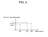
- the front brightness at the middle of the backlight 13 (the brightness of the light exit surface 142 of the transparent substrate 14 in the normal direction) was measured.
- the results are shown in FIG. 2.
- the vertical scale represents a relative front brightness where the front brightness of the example 1 is 1.00.
- the relative front brightness of example 2 and example 3 are 0.93 and 0.74, respectively.
- the relative front brightness to the front brightness when the vertex angle is 90 degrees is equal to or more than 0.9.
- the relative front brightness is equal to or more than 0.7.
- the light scattering films 17 of the examples 4 through 11 respectively have haze of 30 percent, 47 percent, 66 percent, 86 percent, 88 percent, 90 percent, 92 percent and 95 percent, respectively.
- the other components are same to those of the example 1.
- the relative front brightness (a ratio of front brightness) to the front brightness when the haze is 94 percent is equal to or more than 0.9 percent.
- a ratio of front brightness is equal to or more than 0.75.
- front brightness varies depending on haze because a rate of light emitted toward the prism sheet 18 to the light, which has entered into the light scattering film 17, reduces when haze is small.
- the light is largely scattered when emitted through the light scattering film 17 with a large haze and is not efficiently converged.
- the total transmittance to the front light is 46 percent, 50 percent, 58 percent, 75 percent, 76 percent, 87 percent, 88 percent, 93 percent, 97 percent and 99 percent, respectively.
- the other components are same to those of the example 1.
- the relative front brightness to the front brightness when the total transmittance to the front light is 82 percent is equal to or more than 0.95.
- the relative front brightness is equal to or more than 0.9.
- An area lighting unit has an electroluminescent device, a light scattering portion on a side of a light exit surface of the electroluminescent device, and a light converging portion on a side of a light exit surface of the light scattering portion.
- the light converging portion includes first and second layered optical sheets, each having a planar light incidence portion through which light enters and a light exit portion through which the light exits.
- the light exit portion of each optical sheet forms parallel prismatic protrusions, each having a vertex angle of 90 degrees to 105 degrees.
- the optical sheets each are so arranged that the light incidence portion is oriented to the electroluminescent device and a direction in which the protrusions of the first optical sheet are arranged is perpendicular to a direction in which the protrusions of the second optical sheet are arranged.
Landscapes
- Electroluminescent Light Sources (AREA)
- Optical Elements Other Than Lenses (AREA)
Applications Claiming Priority (2)
| Application Number | Priority Date | Filing Date | Title |
|---|---|---|---|
| JP2004164736 | 2004-06-02 | ||
| JP2004164736A JP2005347081A (ja) | 2004-06-02 | 2004-06-02 | 面光源装置 |
Publications (1)
| Publication Number | Publication Date |
|---|---|
| EP1603370A1 true EP1603370A1 (fr) | 2005-12-07 |
Family
ID=34937140
Family Applications (1)
| Application Number | Title | Priority Date | Filing Date |
|---|---|---|---|
| EP05011842A Withdrawn EP1603370A1 (fr) | 2004-06-02 | 2005-06-01 | Unité d'éclairage de zone |
Country Status (6)
| Country | Link |
|---|---|
| US (1) | US20050270763A1 (fr) |
| EP (1) | EP1603370A1 (fr) |
| JP (1) | JP2005347081A (fr) |
| KR (1) | KR20060046382A (fr) |
| CN (1) | CN1704819A (fr) |
| TW (1) | TWI257467B (fr) |
Families Citing this family (9)
| Publication number | Priority date | Publication date | Assignee | Title |
|---|---|---|---|---|
| JP4930246B2 (ja) * | 2007-07-25 | 2012-05-16 | 日本ゼオン株式会社 | 発光素子 |
| DE102008012383B3 (de) * | 2008-03-04 | 2009-06-18 | Fraunhofer-Gesellschaft zur Förderung der angewandten Forschung e.V. | Licht erzeugendes Wandelement |
| JP2010040211A (ja) * | 2008-07-31 | 2010-02-18 | Sumitomo Chemical Co Ltd | 有機エレクトロルミネッセンス素子、その製造方法、照明装置、面状光源、および表示装置 |
| KR101156436B1 (ko) | 2010-01-19 | 2012-06-18 | 삼성모바일디스플레이주식회사 | 광학필름 및 이를 구비하는 유기 발광 디스플레이 장치 |
| JP2011209657A (ja) * | 2010-03-30 | 2011-10-20 | Fujifilm Corp | Led照明用光拡散フィルム |
| DE102012200084B4 (de) * | 2012-01-04 | 2021-05-12 | Pictiva Displays International Limited | Strahlungsemittierendes organisches bauteil |
| JP5758314B2 (ja) * | 2012-01-17 | 2015-08-05 | 株式会社東芝 | 有機電界発光素子、及び照明装置 |
| US9740046B2 (en) * | 2013-11-12 | 2017-08-22 | Nvidia Corporation | Method and apparatus to provide a lower power user interface on an LCD panel through localized backlight control |
| CN105448195A (zh) | 2015-12-16 | 2016-03-30 | 小米科技有限责任公司 | 一种显示装置及电子设备 |
Citations (3)
| Publication number | Priority date | Publication date | Assignee | Title |
|---|---|---|---|---|
| JP2000277266A (ja) * | 1999-03-19 | 2000-10-06 | Toyota Central Res & Dev Lab Inc | 有機電界発光素子 |
| WO2004112442A1 (fr) * | 2003-06-13 | 2004-12-23 | Kabushiki Kaisha Toyota Jidoshokki | Dispositif electroluminescent, son procede de fabrication, et ecran a cristaux liquides faisant appel audit dispositif electroluminescent |
| WO2004112435A1 (fr) * | 2003-06-13 | 2004-12-23 | Kabushiki Kaisha Toyota Jidoshokki | Dispositif electroluminescent, son procede de production, et affichage a cristaux liquides utilisant ce dispositif electroluminescent |
Family Cites Families (11)
| Publication number | Priority date | Publication date | Assignee | Title |
|---|---|---|---|---|
| US4542449A (en) * | 1983-08-29 | 1985-09-17 | Canadian Patents & Development Limited | Lighting panel with opposed 45° corrugations |
| US6052164A (en) * | 1993-03-01 | 2000-04-18 | 3M Innovative Properties Company | Electroluminescent display with brightness enhancement |
| US5598280A (en) * | 1993-03-23 | 1997-01-28 | Dai Nippon Printing Co., Ltd. | Film lens and a surface light source using the same |
| JP2950219B2 (ja) * | 1995-10-13 | 1999-09-20 | オムロン株式会社 | 面光源装置、当該面光源装置を用いた画像表示装置及び当該面光源装置に用いるプリズムアレイ |
| JPH09269418A (ja) * | 1996-03-29 | 1997-10-14 | Enplas Corp | 光制御部材及び面光源装置 |
| EP1975649A1 (fr) * | 1998-02-18 | 2008-10-01 | Minnesota Mining And Manufacturing Company | Film optique |
| KR100271672B1 (ko) * | 1998-05-20 | 2000-11-15 | 구본준 | 시이트 구조의 광학소자 및 그를 이용한 백라이트 유니트 |
| JP2002049324A (ja) * | 2000-07-31 | 2002-02-15 | Nippon Seiki Co Ltd | バックライト装置 |
| US7011420B2 (en) * | 2002-09-04 | 2006-03-14 | Eastman Kodak Company | Planar directed light source |
| JP2005055481A (ja) * | 2003-06-09 | 2005-03-03 | Toyota Industries Corp | 光学素子、面状照明装置及び表示装置 |
| US7147358B2 (en) * | 2003-12-31 | 2006-12-12 | 3M Innovative Properties Company | Cover removal tab for optical products |
-
2004
- 2004-06-02 JP JP2004164736A patent/JP2005347081A/ja not_active Withdrawn
-
2005
- 2005-05-31 TW TW094117759A patent/TWI257467B/zh not_active IP Right Cessation
- 2005-06-01 US US11/143,313 patent/US20050270763A1/en not_active Abandoned
- 2005-06-01 EP EP05011842A patent/EP1603370A1/fr not_active Withdrawn
- 2005-06-01 CN CNA2005100731883A patent/CN1704819A/zh active Pending
- 2005-06-01 KR KR1020050046842A patent/KR20060046382A/ko not_active Ceased
Patent Citations (3)
| Publication number | Priority date | Publication date | Assignee | Title |
|---|---|---|---|---|
| JP2000277266A (ja) * | 1999-03-19 | 2000-10-06 | Toyota Central Res & Dev Lab Inc | 有機電界発光素子 |
| WO2004112442A1 (fr) * | 2003-06-13 | 2004-12-23 | Kabushiki Kaisha Toyota Jidoshokki | Dispositif electroluminescent, son procede de fabrication, et ecran a cristaux liquides faisant appel audit dispositif electroluminescent |
| WO2004112435A1 (fr) * | 2003-06-13 | 2004-12-23 | Kabushiki Kaisha Toyota Jidoshokki | Dispositif electroluminescent, son procede de production, et affichage a cristaux liquides utilisant ce dispositif electroluminescent |
Non-Patent Citations (2)
| Title |
|---|
| DATABASE WPI Section Ch Week 200502, Derwent World Patents Index; Class L03, AN 2004-681461, XP002345366 * |
| DATABASE WPI Section EI Week 200065, Derwent World Patents Index; Class U14, AN 2000-669020, XP002345367 * |
Also Published As
| Publication number | Publication date |
|---|---|
| TWI257467B (en) | 2006-07-01 |
| TW200602586A (en) | 2006-01-16 |
| US20050270763A1 (en) | 2005-12-08 |
| KR20060046382A (ko) | 2006-05-17 |
| CN1704819A (zh) | 2005-12-07 |
| JP2005347081A (ja) | 2005-12-15 |
Similar Documents
| Publication | Publication Date | Title |
|---|---|---|
| EP1538468A2 (fr) | Feuille à prismes, guide de lumière ayant une surface prismatique, et dispositif d'éclairage à base d'une combinaison de ceux-ci | |
| EP1533633B1 (fr) | Dispositif d'illumination planaire | |
| US7980746B2 (en) | Hollow type planar illuminating device | |
| CN102478188B (zh) | 背光单元和使用背光单元的显示装置 | |
| JP4533728B2 (ja) | 液晶表示装置 | |
| US7530720B2 (en) | Backlight unit and display apparatus having the same | |
| JP4691543B2 (ja) | 導光バッファ板を有するバックライトユニット | |
| US20050169012A1 (en) | Optical member and lighting apparatus | |
| EP1662301A1 (fr) | Dispositif d'éclairage et affichage réflectif à cristaux liquides équipé du dispositif d'éclairage | |
| JP4114551B2 (ja) | 補助電極を用いた面状発光装置 | |
| CN101004517A (zh) | 面状光源装置 | |
| JP2000323272A (ja) | 平面光源 | |
| KR20080085242A (ko) | 도광판 및 이를 이용하는 백라이트 어셈블리 | |
| JP2001035225A (ja) | 面状照明装置 | |
| CN106195766A (zh) | 一种背光源、显示装置及其控制方法 | |
| CN100458275C (zh) | 照明装置和液晶显示装置 | |
| EP1603370A1 (fr) | Unité d'éclairage de zone | |
| EP1426790A1 (fr) | Elément optique, unité d'illumination planaire et unité d'affichage à cristaux liquides | |
| CN1683966A (zh) | 导光板及背光模组 | |
| JP2003151333A (ja) | 面照明装置と液晶表示装置 | |
| US20020080597A1 (en) | EL lamp for a front lit display | |
| EP1426812A2 (fr) | Elément optique, unité d'éclairage plan et unité d'affichage à cristaux liquides | |
| JP6477493B2 (ja) | 面発光ユニット | |
| US20090147533A1 (en) | Display Device | |
| CN1227562C (zh) | 轻量化背光模块 |
Legal Events
| Date | Code | Title | Description |
|---|---|---|---|
| PUAI | Public reference made under article 153(3) epc to a published international application that has entered the european phase |
Free format text: ORIGINAL CODE: 0009012 |
|
| 17P | Request for examination filed |
Effective date: 20050601 |
|
| AK | Designated contracting states |
Kind code of ref document: A1 Designated state(s): AT BE BG CH CY CZ DE DK EE ES FI FR GB GR HU IE IS IT LI LT LU MC NL PL PT RO SE SI SK TR |
|
| AX | Request for extension of the european patent |
Extension state: AL BA HR LV MK YU |
|
| AKX | Designation fees paid |
Designated state(s): DE FI GB NL |
|
| STAA | Information on the status of an ep patent application or granted ep patent |
Free format text: STATUS: THE APPLICATION IS DEEMED TO BE WITHDRAWN |
|
| 18D | Application deemed to be withdrawn |
Effective date: 20080103 |