EP1603785B1 - Zustandsüberwachungsvorrichtung für gleisstromkreise und verfahren - Google Patents
Zustandsüberwachungsvorrichtung für gleisstromkreise und verfahren Download PDFInfo
- Publication number
- EP1603785B1 EP1603785B1 EP04714833A EP04714833A EP1603785B1 EP 1603785 B1 EP1603785 B1 EP 1603785B1 EP 04714833 A EP04714833 A EP 04714833A EP 04714833 A EP04714833 A EP 04714833A EP 1603785 B1 EP1603785 B1 EP 1603785B1
- Authority
- EP
- European Patent Office
- Prior art keywords
- frequency
- track circuit
- track
- condition
- transmitter
- Prior art date
- Legal status (The legal status is an assumption and is not a legal conclusion. Google has not performed a legal analysis and makes no representation as to the accuracy of the status listed.)
- Expired - Lifetime
Links
- 238000012544 monitoring process Methods 0.000 title claims abstract description 40
- 238000000034 method Methods 0.000 title claims description 25
- 238000012545 processing Methods 0.000 claims abstract description 49
- 238000004891 communication Methods 0.000 claims description 18
- 239000003990 capacitor Substances 0.000 claims description 16
- 238000001228 spectrum Methods 0.000 claims description 16
- 238000004458 analytical method Methods 0.000 claims description 15
- 230000008859 change Effects 0.000 claims description 12
- 239000000463 material Substances 0.000 claims description 9
- 230000009467 reduction Effects 0.000 claims description 7
- 230000003595 spectral effect Effects 0.000 claims description 7
- CWYNVVGOOAEACU-UHFFFAOYSA-N Fe2+ Chemical compound [Fe+2] CWYNVVGOOAEACU-UHFFFAOYSA-N 0.000 claims description 6
- 238000010183 spectrum analysis Methods 0.000 claims description 6
- 238000013528 artificial neural network Methods 0.000 claims description 5
- 239000000835 fiber Substances 0.000 claims description 4
- 230000002452 interceptive effect Effects 0.000 claims description 2
- 230000011664 signaling Effects 0.000 description 8
- 230000006870 function Effects 0.000 description 6
- 230000004044 response Effects 0.000 description 6
- 210000002569 neuron Anatomy 0.000 description 5
- 230000003287 optical effect Effects 0.000 description 5
- 230000008901 benefit Effects 0.000 description 4
- 238000002955 isolation Methods 0.000 description 4
- 238000005259 measurement Methods 0.000 description 4
- 230000008569 process Effects 0.000 description 3
- RYGMFSIKBFXOCR-UHFFFAOYSA-N Copper Chemical compound [Cu] RYGMFSIKBFXOCR-UHFFFAOYSA-N 0.000 description 2
- 229910052802 copper Inorganic materials 0.000 description 2
- 239000010949 copper Substances 0.000 description 2
- 238000013016 damping Methods 0.000 description 2
- 238000013500 data storage Methods 0.000 description 2
- 238000001514 detection method Methods 0.000 description 2
- 238000001914 filtration Methods 0.000 description 2
- 230000004907 flux Effects 0.000 description 2
- 239000007769 metal material Substances 0.000 description 2
- 238000012986 modification Methods 0.000 description 2
- 230000004048 modification Effects 0.000 description 2
- 238000005096 rolling process Methods 0.000 description 2
- 238000009781 safety test method Methods 0.000 description 2
- 230000003068 static effect Effects 0.000 description 2
- 239000000956 alloy Substances 0.000 description 1
- 229910045601 alloy Inorganic materials 0.000 description 1
- 230000002238 attenuated effect Effects 0.000 description 1
- 230000006399 behavior Effects 0.000 description 1
- 210000004027 cell Anatomy 0.000 description 1
- 230000001413 cellular effect Effects 0.000 description 1
- 239000004020 conductor Substances 0.000 description 1
- 230000008878 coupling Effects 0.000 description 1
- 238000010168 coupling process Methods 0.000 description 1
- 238000005859 coupling reaction Methods 0.000 description 1
- 230000001934 delay Effects 0.000 description 1
- 230000001419 dependent effect Effects 0.000 description 1
- 238000010586 diagram Methods 0.000 description 1
- 230000000694 effects Effects 0.000 description 1
- 238000010292 electrical insulation Methods 0.000 description 1
- 239000012777 electrically insulating material Substances 0.000 description 1
- 230000007613 environmental effect Effects 0.000 description 1
- 238000009434 installation Methods 0.000 description 1
- 238000010295 mobile communication Methods 0.000 description 1
- 238000012806 monitoring device Methods 0.000 description 1
- 239000013307 optical fiber Substances 0.000 description 1
- 230000010355 oscillation Effects 0.000 description 1
- 230000003071 parasitic effect Effects 0.000 description 1
- 230000035699 permeability Effects 0.000 description 1
- 230000008439 repair process Effects 0.000 description 1
- 230000004936 stimulating effect Effects 0.000 description 1
- 238000012549 training Methods 0.000 description 1
- 230000003442 weekly effect Effects 0.000 description 1
Images







Classifications
-
- B—PERFORMING OPERATIONS; TRANSPORTING
- B61—RAILWAYS
- B61L—GUIDING RAILWAY TRAFFIC; ENSURING THE SAFETY OF RAILWAY TRAFFIC
- B61L1/00—Devices along the route controlled by interaction with the vehicle or train
- B61L1/20—Safety arrangements for preventing or indicating malfunction of the device, e.g. by leakage current, by lightning
Definitions
- This invention relates to the field of condition monitoring. More specifically it relates to the condition monitoring of railway infrastructure such as track circuits.
- a track circuit is an electrical circuit which includes a length of running rails and permits the detection of the presence of a train.
- a track circuit may also be used to communicate commands, instructions, or indications between the wayside and the train. Track circuits provide information on the location of the trains, and this information may be used to command train speeds and is used to operate signalling so that the trains operate safely.
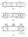
- FIG. 1 schematically illustrates a basic DC track circuit.
- the electrical signal is a direct current.
- the signal source 10 in this case a battery, is connected at one end of the track circuit while a receiver 12 is connected to the other end to detect the electrical signal.
- the receiver 12 is normally a relay.
- When no train is present on the track the relay is energised by the current flowing through the track circuit.
- jointed tracks the tracks are isolated into sections by use of insulated joints 14 in the running rails 16.
- the insulated joints 14 provide electrical insulation between a given track circuit and the abutting tracks which form part of adjacent track circuits.
- the wheel set 18 of the train causes a short circuit and the relay in that section de-energises.
- FIG. 2 schematically illustrates a basic AC track circuit.
- An AC source 20 is coupled to the rails 16 by a transformer and capacitor (not shown) at one end of the track circuit whilst the receiver 12 (a relay) is connected to the other end.
- the rails 16 still have insulated joints 14 but a pair of centre tapped impedance bonds 22 connect the rails 16 either side of the insulated joints 14. The centre taps of each one of the pair of the impedance bonds 22 are joined together.
- the purpose of the impedance bonds 22 is to maintain continuity for the return of the DC traction current shared equally in the two running rails 16. The impedance bonds 22 do this while still maintaining a high impedance at the signalling frequencies between the two rails 16 and between adjacent track circuits.
- Figure 3 schematically illustrates an untuned audio frequency AC track circuit employing an "end-fed" topology.
- the rails 16 have a self-inductance of 1mH/km, therefore a source 26 operating at audio frequencies (e.g., 1kHz) is provided that can operate without being short circuited. It is now possible to locate the AC source 26 and a receiver 28 across the track so that neither will be shunted.
- the track circuit illustrated in figure 3 comprises a first rail shunt 24, a second rail shunt 25 and a pair of running rails 16 connecting the first 24 and second 25 rail shunts together.
- the length of track (zone D1) between the AC source 26 and first rail shunt 24 and the length of track (zone D2) between the receiver 28 and second rail shunt 25 are both 100 m long. These distances are sufficiently large so that the AC source 26 and receiver 28 are not short circuited. Therefore, with no wheel set 18 present anywhere on the rails 16 between the source 26 and the receiver 28 (zone D3), the signal transmitted by the source 26 will be picked up by the receiver 28 and the track relay 30 will be energised. When a wheel set 18 (not shown in Figure 3 ) enters zone D3 the received signal will be attenuated and the track relay will drop.
- Audio frequency AC track circuit illustrated in Figure 3 is termed 'end fed' because the transmitter is at one end of the track circuited section and the receiver is at the other end. Audio frequency track circuits can also have a 'centre-fed' topology. In this topology the transmitter is situated at the centre of the track circuited section with two receivers located at respective ends of the section.
- a problem with untuned track circuits is that there will always be sections of track (dead zones), i.e. zones D1 and D2, where the presence of a wheel set 18 cannot be detected.
- the solution to this problem requires a tuned AC track circuit.
- Figure 4 schematically illustrates a tuned audio frequency AC track circuit.
- the track is divided into sections by shunts 32 formed by an inductor L and a capacitor C in series.
- the shunts are frequency selective such that the short circuit corresponds to a particular spot frequency.
- F1 and F2 along the track in the sequence F1-F2-F1-F2 etc. it is possible to divide the track into overlapping sections. In this way train detection can be achieved over the entire track distance without any dead zones.
- a proprietary track circuit that adopts this method is the TI style 21 track circuit.
- the TI style 21 track circuit is widely used on British railways.
- Railways normally consist of one or more pairs of carriageways; designated up road(s) and a down road(s).
- the TI21 track circuit divides the roads into pairs of operating frequencies, alternating every section.
- the frequencies or channels used in the TI21 track circuit are allocated the letters and designations as set out in table 1.
- "Track Section 1" and "Track Section 2", referred to in the table are adjacent sections of track.
- the "Road Condition" referred to in the table, specifies the direction of travel ("up” or "down") of a train on a particular railway and whether the train is a stopping service ("slow") or non-stopping service ("fast”).
- the terms “fast” and “slow” are only generalisations and need not necessarily define line speeds in all cases.
- the frequencies listed in table 1 are the centre frequencies of a frequency modulated signal.
- the signal deviates by ⁇ 17 Hz at a rate of 4.8 Hz.
- FIG. 5 schematically illustrates a simplified TI21 track circuit employing an end-fed topology where a single transmitter feeds one section to a single receiver at the opposite end.
- the track circuit comprises a first tuned zone 33 between points X1 and X2, a kilometre section of track between points X2 and X3, and a second tuned zone 35 between points X3 and X4.
- a transmitter TxA located in the first tuned zone 33 provides a source of audio frequency AC energy at frequency A into the running rails 16 at point X2.
- a shunt 34 comprising an inductor LA in series with a capacitor CA, is located at point X1. The shunt prevents current with a frequency A from travelling leftwards beyond point X1.
- the energy from the transmitter TxA is picked up by a receiver RxA at position X3 in second tuned zone 35.
- a tuning capacitor CpA is connected in parallel to the receiver RxA.
- the capacitor CpA tunes the two lengths of rail in the second tuned zone 35 to frequency A.
- the shunt 34 at position X4 shunts the rails 16 at frequency A.
- the operation of the circuits in the two tuned zones 33, 35 is to select frequency A and convey it to the receiver RxA.
- This receiver RxA has additional bandpass filtering to enhance the rejection of frequencies from adjacent track circuits.
- the tuned zone operating at frequency B operates in the same way, with equivalent components that are tuned to frequency B.
- TTU Track Tuning Unit
- FIG. 6 schematically illustrates a simplified TI21 track circuit employing a centre-fed topology.
- a transmitter 99 (and its accompanying TTU) is situated at the centre of the track circuit with two receivers (and TTUs) 101, 106 located at the respective ends of the track circuit.
- the T121 track circuit employs tuned zones that comprise multiple transmitters and receivers, for example, utilising a tuned zone with two transmitters and a tuned zone with two receivers.
- a feature of the TI 21 track circuits is that the self inductance of the rails 16 is one of the tuned elements in a tuned zone.
- the circuit that makes up a tuned track zone comprises a 20 m length of track and two TTUs
- a track circuit may fail for one of several reasons. Typical causes of failure include:
- EP-A-958986 discloses a monitoring system which consists essentially in the fact that operating characteristic variables of a track release signalling system such as the feed voltage and the signal voltages and, if appropriate, the phase angle of the voltage measured values in the quiescent state (of the signalling system) are fed to a separate monitoring device, independently of the signalling system, the operating characteristic variables being measured and evaluated as a function of time.
- the track release signalling system contains at least one motor track relay and the track has insulated rail sections. Signal voltages are tapped off at the insulated rail sections. The signal voltages and phase angles of signal voltages are measured and monitored. In one embodiment they are compared with know operating parameters.
- an apparatus for monitoring the condition of an alternating current track circuit comprising: a sensor for sensing a current in the track circuit when arranged in proximity to, but not contacting, the track circuit; an analogue to digital converter operable to convert the sensed current to a digital signal; and a processor operable to receive the digital signal from the analogue to digital converter and to perform signal processing on the digital signal, said signal processing providing a parameter indicative of the condition of the track circuit.
- a system for monitoring the condition of an alternating current track circuit comprising: a plurality of sensing modules; and a communication link between the modules, wherein each sensing module comprises the apparatus as set forth in the aforementioned aspect of the invention.
- Embodiments of the invention which provide particular benefit relate to the apparatus and methods for monitoring alternating current track circuits, wherein the alternating current track circuit is operable with an alternating current which oscillates at audio frequencies.
- non-contacting monitoring system allows the system to be deployed on an operational track without the vigorous safety testing and approval that would otherwise be necessary.
- a non-contacting monitoring system provides further advantages including the provision of portable apparatus thereby allowing the optimum position of the apparatus, for a particular mode of operation of the apparatus, to be readily found.
- the apparatus may be easily moved to be adjacent to various parts of the track circuit depending on the fault or potential fault being investigated.
- a suitably designed apparatus can make measurements up to several metres from the track circuit thereby allowing personnel to have access to the monitoring apparatus without exposing the personnel to the risk of moving rolling stock.
- a non-contacting apparatus measuring the track current would not affect the track current and therefore would not invalidate the results obtained by the apparatus.
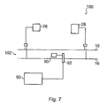
- Figure 7 is a schematic illustration of the arrangement of a sensor unit 90 and a processing module 50 in relation to an end-fed track circuit 100.
- the track circuit 100 comprises a tuned zone as described above having a transmitter 26 and a receiver 28.
- the sensor is housed separately from the processing module 50 in a separate sensing unit 90 which is placed between the rails 16 of the track circuit 100.
- the sensor unit 90 may also be placed to one side of the railway 102.
- the signals from the sensor unit 90 are fed via a conduit 92 to the processing module 50.
- the conduit is constructed from reinforced and electrically insulating material.
- the senor is a magnetic field sensor which senses the magnetic field produced by the current circulating in the track circuit.
- the sensor comprises a helical coil.
- the sensor responds to the rate of change of the magnetic field to eliminate the effects of static magnetic fields.
- the sensor unit 90 is in proximity to, but not in contact with, the track circuit.
- the processing module 50 preferably performs a spectral analysis of the signal produced by the sensor to produces a parameter or parameters indicative of the condition of the track circuit. Alternatively, the processing module may analyse the time envelope of the detected non-static magnetic field.
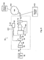
- FIG 8 is a schematic illustration of the processing module 50.
- the processing module 50 has an input port 52 to receive an electrical sensor signal from the sensing unit 90.
- the sensing unit 90 may be housed in the processing module 50.
- the sensing unit 90 monitors the electrical current flowing through a track circuit.
- the sensing unit 90 can be arranged to monitor the current flowing through the rails 16 or the current flowing through other parts of the track circuit.
- the signal from the sensing unit 90 is passed through isolation electronics 54 so that the remaining components in the processing module 50 are protected from excessive current surges impressed upon the sensor signal an dto reject any source of common mode interference.
- the isolation electronics 54 which may utilise optical or transformer coupling, may be of a proprietary type or may be purpose built for the processing module 50.
- An amplifier 56 is connected to the isolation electronics 54 to receive the sensor signal.
- the amplifier 56 amplifies the sensor signal so that the sensor signal is at an amplitude appropriate for further processing in the processing module 50.
- An analogue to digital converter (ADC) 58 is connected to the amplifier to receive the amplified sensor signal and convert it to a digital signal: The digital signal is then optionally passed through a digital filter 60 to remove low frequency noise in the sensor signal. It may also be appropriate to use an analogue filter to condition the sensor signal before it enters the ADC 58 to further enhance interference rejection and eliminate aliasing.
- ADC analogue to digital converter
- a microprocessor 64 is connected to the digital filter 60 so that signal processing is performed on the filtered digital signal.
- the microprocessor 64 is connected to a memory unit 66 so that the processed signal and parameters derived from the processed signal may be stored.
- the memory unit 66 may be a random access memory (RAM), for example a non-volatile RAM such as a battery maintained RAM.
- the processed signal from the microprocessor 64 may be outputted to a second amplifier 68 for driving a serial communications link.
- the second amplifier 68 amplifies the processed signal so that the processed signal is at a level appropriate for further processing by a communications microprocessor 70 which may be optionally located remote from the main processing module 50.
- the communications microprocessor 70 receives the signal from the amplifier and/or the parameters derived from the processed signal and provides them to a communication port 72.
- the communication port 72 may be connected to a communication network 104.
- the communication network 104 may be an Integrated Services Digital Network (ISDN), the Internet, a cellular telephone system (e.g., a Global System for Mobile Communications (GSM system)), a telemetry system or a local area network (LAN), for example Ethernet.
- ISDN Integrated Services Digital Network
- GSM Global System for Mobile Communications
- LAN local area network
- the communication network 104 is connected to remote analysis system 105.
- the remote analysis system 105 provides for further processing and/or analysis of the sensor signal.
- the communication port 72 can, alternatively or additionally, be lined to a computer, data logger or digital storage device/medium 103 to allow the data to be downloaded from the microprocessor 64 or the memory unit 66.
- the processing module 50 has both microprocessors 64, 70 and a data logger 62.
- the data logger 62 is preferably connected to the digital filter 60 to store the filtered digital sensor signal.
- the data logger 62 can also connect to the ADC input depending on the purpose of the monitoring: in this instance the data logger can be based upon a digital computer using an analogue to digital converter, a sound card, a random access memory or a digital tape recorder to capture the data. If the sensor signal comprises signals in the audio frequency range then a sound card or a digital audio tape recorder may be particularly appropriate for use as the data logger 62.
- the data logger 62 has a port 63 to allow data stored in the data logger 62 to be accessed.
- Data may be fed from the data logger port 63 or from an analogue port 631 to a digital audio tape recorder.
- a digital audio tape recorder is a Sony TCD-D8 DAT recorder.
- the sensing unit 90 comprises a sensor circuit that includes a non-contact sensor that is responsive to the current in the track circuit.
- the sensor is a helical coil that responds to the rate of change of the magnetic field. The use of such a sensor means that the sensor can operate without physical contact to the track circuit.
- a non-contacting sensor allows a track circuit monitoring system to be deployed on or adjacent to an operational track without the vigorous safety testing and approval that would otherwise be necessary.
- a non-contacting sensor provides further advantages including the provision of portable apparatus which will allow the optimum position of the apparatus to be readily found, the optimum position being different for the different configurations (end-fed, centre-fed etc.) of the track circuit.
- the apparatus in a portable implementation, may be easily moved to be adjacent to various parts of the track circuit depending on the fault or potential fault being investigated.
- the apparatus can make measurements up to several metres from the track circuit thereby allowing personnel to have access to the monitoring apparatus without exposing the personnel to the risk of moving rolling stock.
- the non-contacting sensor measuring the track current is designed so that it does not affect the track current.
- the senor is a coil of metallic material.
- the metallic material is substantially non-ferrous so that the coil will not influence the electrical performance of the components of the track circuit.
- An illustrative material for the coil is copper or an alloy in which copper is the major component.
- An example of the sensor is an air-cored coil.
- Another example of the sensor is a coil in which the core of the coil contains material, for example material chosen for its specific electromagnetic properties (e.g., permittivity or permeability).
- the sensor is a coil that is part of a printed circuit board (PCB).
- PCB printed circuit board
- An example of a printed circuit board coil 78 is shown in figure 9A .
- the PCB coil 78 may have numerous configurations, the PCB coil 78 shown in figure 9 , by way of example only, covers an area with a length (L) of 89 mm, a width (W) of 81 mm, with the track that makes up the coil having width (t) of 0.254 mm and the coil having 70 turns with the distances between the turns being 0.254 mm.
- coil 781 having an air-core, or having a core 782 chosen for its specific electromagnetic properties; see ( Figure 9B ).
- Figure 10 schematically illustrates a printed circuit board 76 having a coil 78 and various electronic components of the processing module 50.
- the coil 78 is a printed circuit on the board 76.
- a printed circuit board coil 78 can be manufactured integrally on a circuit board along with the various signal condition monitoring electronics 50 including the microprocessors 64 and 70.
- a printed circuit board coil 78 can be manufactured with a thickness comparable with the thickness of a printed circuit board (a typical printed circuit having, for example, a thickness of about 1.5 mm).
- the printed circuit board 76 will take up little space and can be housed in a small container which can be easily deployed adjacent to a track circuit or between the running rails 16.
- a printed circuit board coil 78 can be easily manufactured to follow a geometry chosen by a designer to suit a particular application.
- Figures 9A and 10 show a PCB coil 78 in one such configuration. Of course, the PCB coil is not limited to the configuration illustrated.
- a PCB coil may be less sensitive to magnetic fields than a wire wound coil.
- a PCB coil is preferable when the sensing unit 90 is allowed to be positioned between the rails. However, that may not be allowed due to safety concerns in the installation of the sensor.
- a wire wound coil 781 ( Figure 9B ) can be more sensitive and is preferably used in a sensing unit 90 for use adjacent to, but spaced from, the track.
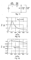
- Figure 11 is a schematic illustration of a circuit that is equivalent to the sensor circuit.
- a resistor R and an inductor L placed in series represent the resistance and inductance of the sensing coil.
- An illustrative value of resistance of the resistor R is 250 Ohms.
- the inductor L can take any inductance value in the range 1-500 mH; an illustrative value of inductance is 500 mH.
- the inductor has a fixed inductance.
- Placed in series with the coil is a tuning capacitor Ct.
- the capacitor Ct has a fixed capacitance in the range 4.7 nF-3.3 ⁇ F.
- An illustrative capacitance is 10 nF, however when distributed parasitics are taken into account the effective capacitance of the circuit is closer to 11 ⁇ F.
- the sensor circuit is designed to be in low resonance (having a low Q factor).
- the Q factor is in the range 0.5 - 5.
- Rload represents the resistance of the monitoring electronics plus the resistance of an additional resistor, the value of which is chosen to give Rload a particular value.
- the resistor Rload has a resistance in the range 1-10 k ⁇ , an illustrative value of resistance is 10 k ⁇ .
- FIGs 12 and 13 graphically illustrate the frequency response (pick up response) of the track circuit for two different values of load resistance. It can be seen from figures 12 and 13 that the full width at half maximum (FWHM) of the frequency response depends strongly on the damping resistor Rload; the larger the value of the resistor the smaller the FWHM of the coil pickup response. The value of Rload is chosen to achieve a desired Q factor.
- the electromotive force induced in the coil 78 ( Figure 9 ) by a magnetic field is proportional to the product of the cross-sectional area of the coil that intersects the radiated magnetic field (the collection area) with the rate of change of the flux density of that magnetic field.
- the coil is orientated relative to the track circuit so as to maximise the collection area.
- processing circuit 50 can be modified in many ways and that there will be many circuits that will be substantially equivalent to the circuit 50 schematically illustrated in figure 8 .
- the sensor can be used to monitor currents throughout the track circuit.
- the running rails 16 are an integral part of the track circuit and it may be convenient to position the sensor adjacent to the running rails 16.
- the use of the sensor in this way can provide not only information on the integrity of the track circuit but can also provide information on the relative levels of traction current flowing in the running rail ( to which it is adjacent) by responding to the ripple component.
- the sensor may be placed between the running rails 16 (an area known in the rail industry as the "four-foot" although the techniques and apparatus described in this application are not limited to any particular gauge of railway). If a section of railway comprises more than one road then the placing of the sensor in the four foot of one particular road will cause the sensor to pick up substantially only frequencies present in the track circuit of that particular road. The sensor may be placed in the centre of the four-foot since this position provides the most stable and predictable magnetic flux density for a given current flowing in the track circuit.
- a suitably designed sensor can monitor track currents when placed on the wayside up to several metres from the railway. Placing the sensor outside the four-foot may be preferable on safety grounds.
- the senor is positioned towards the centre of a tuned zone because it is often the condition of the tuned zone that determines the operability of the associated track circuits either side of the tuned zone. Siting the sensor outside of the tuned zone towards the centre of the track circuited section may also offer more useful data with regard to ballast condition.
- the digital signal produced by the ADC 58 from the sensor signal undergoes digital signal processing.
- the digital signal processing is now described in relation to a TI style 21 track circuit, however, the skilled person will appreciate that similar digital processing can be applied to the sensor signal from any AC track circuit.
- a digital signal processor for example as provided by the microprocessor 64 performs a frequency analysis (e.g., a Fourier transform of the sensor signal) to determine the spectrum of the sensor signal.
- the frequency information in the digital signal provides a rich source of information on the condition of the track circuit.
- the frequency of 2296 Hz is one of the standard operating frequencies used in the operation of TI style 21 track circuits.
- plots I, II, III and IV are illustrated in figure 14 .
- Plots I and II are respectively for measurements taken on a TTUs in which there is no fault.
- Plots III and IV correspond respectively to plots I and II but in which there is a tail connection fault in the TTU connected to the receiver.
- the connection fault was simulated by adding a 0.5 Ohm resistor to the tail connection.
- the ratio of the voltage across one TTU to the adjacent TTU, at a particular frequency is called the "rejection ratio".
- the tail connection fault is also apparent from an analysis of the current circulating in the tuned zone as will now be described with reference to Figures 15 and 16 .
- Figure 15 is a graphical representation of the current flowing in the TTU when there is no fault in the TTU.
- Figure 16 is a graphical representation of the current flowing in the TTU when the 0.5 Ohm tail connection fault is present.
- Two spectral components are clearly visible in each figure, these respectively correspond to frequencies A and B at which adjacent TTUs operate. It can be seen that the spectral component at frequency A drops from a magnitude of 4.7 Amps when the unit is fault free to a magnitude of 0.6 Amps when the fault is present.
- the spectral component at frequency B drops from a magnitude of 16 Amps when the unit is fault free to a magnitude of 7 Amps when the fault is present.
- a special fault condition not necessarily indicative of a fault to that of the tuned zone being monitored, is exposed if one spectral component drops in amplitude in the presence of the neighbouring component remaining constant.
- the microprocessor 64 can be programmed to process the digital sensor signal so that an output is given that corresponds to that of poor rejection ratio or to the magnitude of the current at one or more pre-determined frequencies.
- the microprocessor 64 can be programmed to give a warning when the estimated rejection ratio or the magnitude of a current indicates a failure of the track circuit.
- the microprocessor 64 will be programmed so that a warning can be given when a fault has been predicted in either the near, medium or distant future.
- the microprocessor 64 may also process the digital sensor signal by performing a spectral analysis on the sensor signal.
- Figure 17 shows a spectrum of the digital sensor signal obtained by operating the sensor outside of the four-foot, line side within the vicinity of two closely positioned tuned zones in up and down roads.
- the spectrum illustrated in Figure 17 shows frequency components that match the pre-set TI-21 frequencies A, B, C and D, and was recorded when there was no train present in either track sections or tuned zones.
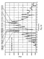
- Figure 18 illustrates a spectrum recorded when a train enters the channel A track section. It can be readily seen that the amplitude of the signal at frequency A drops by several decibels when a train enters the section and short circuits the track circuit.
- Figure 19 illustrates a detailed spectrum centred about frequency A.
- the detailed spectrum clearly shows a central peak with upper and lower side lobes on which a modulation frequency is imposed.
- Table 2 compares the frequency of these features with the frequencies specified for that of TI 21 channel A. Table 2 A comparison of parameters measured by the processing module with theoretical values Parameter Specified Measured Upper lobe frequency (Hz) 1716 1715.1 Lower lobe frequency (Hz) 1682 1684.6 Calculated Median (Hz) 1699 1699.9 Positive deviation (Hz) +17 +15.3 Negative deviation (Hz) -17 -15.3 Modulation Rate 4.8 4.6
- Relationships between parameters of the sensor signal and conditions of the track circuit can be determined by field trials.
- the microprocessor 64 operates on one or more algorithms.
- the algorithm on which the microprocessor 64 operates is set to sample the sensor signal at predetermined intervals, for example, hourly, daily, or weekly according to the condition being monitored. In this way it is possible to track a drift in a particular frequency or set of frequencies and to sound a warning if the drift is greater than a pre-set value. The same would also be true when looking at the magnitude of particular frequency features.
- the microprocessor 64 may be provided with a library of spectra each of which corresponds to a fingerprint of a particular failure mode. The microprocessor 64 may be set up to compare the frequency spectrum of the sensor signal with the spectra held in the library so that an early warning may be given of an impending failure in the track circuit.
- the microprocessor 64 can be arranged to digitally process the sensor signal so as to monitor the current flowing in the track circuit in the time domain.
- the current at a given frequency will follow a substantially sinusoidal short-term time profile since the transmitter is a harmonic rich alternating current source stimulating a high Q tuned circuit.
- a time profile that follows a truncated sine wave or an otherwise distorted waveform may indicate a fault in the track circuit.
- Monitoring the current in the time domain over a longer period will consolidate the findings of poor tuning. For example if the envelope of the audio carrier is observed to modulate substantially in amplitude in sympathy with the rate of frequency modulation, this would indicate that the frequency modulation of the transmitter was not centred on or close to the natural frequency of the tuned zone.
- the time variation of the envelope 64 of the detected signal is analysed.
- an individual TI21 frequency component is extracted and the characteristic of the amplitude modulation thereof is analysed. That provides an indication of the condition of the tuned zone and/or more TTUs.
- analogue signal processing may be used instead of digital signal processing.
- the microprocessor 64 is an intelligent processor that can be trained to recognise faults. More preferably the condition monitoring units are connected to form a network.
- a neural network may be formed by incorporating in each monitoring unit one or more simple processors ("neurons"), each neuron possibly having a small amount of local memory.
- the neurons are connected by unidirectional communication channels ("connections"), which carry numeric data.
- the neurons can, for example be elementary non-linear signal processors (in the limit they are simple threshold discriminators).
- Each neuron is preprogrammed and continuously active. The units operate only on their local data and on the inputs they receive via the connections.
- the neural network has a "training" rule whereby the weights of connections are adjusted on the basis of presented patterns. In other words, the neural networks will "learn” from examples and exhibit a structural capability for generalisation.
- a neural network will be advantageous to the present application by providing a monitoring system that can learn about the behaviour and failure modes of track circuits.
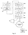
- Figures 20 and 21 schematically illustrate an alternative arrangement for the sensor and the processing electronics.
- the signal condition monitoring electronics comprising, for example, the isolation electronics, amplifiers, ADC 58 and electronic filters, may be housed together with the sensor in a sensing/condition monitoring module 94.
- the sensing/condition monitoring module 94 can be situated between the rails 16 or to the side of the railway 102.
- a signal is then fed from the sensing/processing module 94, via a conduit, to a site computer 96, laptop computer or purpose built processor.
- the site computer 96, laptop computer or processor comprise, for example, an interface card 961 for receiving the signal from the sensing/condition monitoring module 94, control software 962 to perform signal processing on the signal received from the sensing/condition monitoring module 94, data storage unit 963 and a data link 964.
- the data storage unit 963 is used for storing the signal from the sensing/processing module 94 or for storing the signal after it has been processed by the control software.
- the data link 964 provides access to the stored data via a network 104 by a remote system 105 so that the data may be further analyse.
- the data link is accessed by a zip drive, digital tape recorder or other similar device 98 so that the data can be stored on a portable medium, the portable medium then being taken away so that the data stored on it can undergo further analysis by the remote analysis system 105.
- FIGs 22 to 24 schematically illustrate a monitoring system in which a plurality of monitoring modules 50 and/or sensing/condition monitoring modules 94 are connected by a communication network 104 to the remote analysis system 105.
- the modules 50, 94 may be connected to the remote analysis system 105 according to a number of different geometries: Figure 22 illustrates a star geometry; Figure 23 illustrates a ring geometry; and Figure 24 illustrates a spur geometry.
- the configuration of the monitoring system deployed on a railway network is likely to involve a combination of these geometries.
- a fibre optic magnetic field sensor comprising one or more coils of optical fibre is placed adjacent to the rails.
- the use of a fibre optic sensor would require a light source and photoelectric cell for converting the optical signal from the optical sensor into an electrical signal.
- the control software can be stored on a portable medium, for example but not limited to, a magnetic disc, an optical disc such as a CD or a digital tape.
- the control software is stored as firmware or placed in a read only memory that is present in the computer 60, laptop computer, processor or in the modules 50, 94.
- the computer, laptop computer, processor or the modules 50, 94 can be linked to a central computer to download data or to receive new or replacement software from the central computer.
- the central computer may also provide updated parameters, frequency ranges and warning limits etc. on which the software will operate.
- portable equipment comprising sensor unit 90 preferably comprising a wire-wound coil 78 as the magnetic field sensor and a signal processor 50 which may include a data logger and/or a signal analyser which produces an indication of a fault.
- the signal analyser may be a frequency spectrum analyser as described above. Alternatively, it may analyse the time varying envelope of the detected signal using a digital signal processor or an analogue processor as described above.
- the portable equipment may include a display 106 for displaying the results of the signal analysis.
Landscapes
- Engineering & Computer Science (AREA)
- Automation & Control Theory (AREA)
- Mechanical Engineering (AREA)
- Train Traffic Observation, Control, And Security (AREA)
- Measurement Of Current Or Voltage (AREA)
- Monitoring And Testing Of Transmission In General (AREA)
- Analysing Materials By The Use Of Radiation (AREA)
Claims (36)
- Vorrichtung zum Überwachen des Zustands eines Wechselstrom-Gleisstromkreises (100), umfassend:einen Sensor (90) zum Messen des Wechselstroms des Wechselstrom-Gleisstromkreises, wobei dieser nahe dem Gleisstromkreis, ohne diesen zu berühren, angeordnet ist;ein Analog-Digital-Wandler (58), der dazu dient, den gemessenen Strom in ein digitales Signal zu wandeln, undeinen Prozessor (50), der dazu dient, das digitale Signal vom Analog-Digital-Wandler zu empfangen und das digitale Signal zu verarbeiten, wobei diese Signalverarbeitung einen Parameter liefert, der den Zustand des Gleisstromkreises angibt.
- Vorrichtung nach Anspruch 1, wobei der Sensor (90) in der Nähe des Gleisstromkreises (100), ohne diesen zu berühren, angeordnet ist, um den Wechselstrom im Wechselstrom-Gleisstromkreis zu messen.
- Vorrichtung nach Anspruch 1 oder 2, ferner umfassend einen zum Speichern des digitalen Signals ausgelegten Datenspeicher (103).
- Vorrichtung nach einem der Ansprüche 1 bis 3, wobei der Prozessor (50) dazu ausgelegt ist, eine Spektralanalyse des gemessenen Gleisstroms durchzuführen, und der Parameter aus der Spektralanalyse abgeleitet wird.
- Vorrichtung nach einem der Ansprüche 1 bis 4, wobei der Prozessor (50) dazu ausgelegt ist, einen Trend in dem Parameter anzugeben, um das Einsetzen eines Versagens des Gleisstromkreises anzugeben.
- Vorrichtung nach einem der Ansprüche 1 bis 5, wobei der Prozessor (50) dazu ausgelegt ist, eine Analyse der zeitabhängigen Hülle des gemessenen Gleisstroms durchzuführen.
- Vorrichtung nach einem der Ansprüche 1 bis 6, wobei der oder die gemessenen Parameter einer oder mehrere der folgenden sind:(i) eine Frequenzverschiebung eines oder mehrerer Frequenzmerkmale;(ii) die Frequenzamplitude bei einer oder mehreren Frequenzen;(iii) die integrierte Intensität eines oder mehrerer Frequenzmerkmale über einen Frequenzbereich;(iv) die Veränderung der Form des Frequenzprofils einer oder mehrerer Frequenzmerkmale;(v) das Amplitudenverhältnis zweier Frequenzwerte;(vi) ein Wobbeln zwischen zwei oder mehreren Frequenzwerten;(vii) das Vorliegen einer Frequenzmodulationscharakteristik;(viii) das in einem bestimmten Frequenzbereich gemessene Profil des Stroms gegen die Zeit;(ix) das Vorliegen einer Amplitudenmodulationscharakteristik.
- Vorrichtung nach einem der Ansprüche 1 bis 6, wobei der Zustand des überwachten Gleisstromkreises einer oder mehrere der folgenden sind:(i) Abdriften bei einer oder mehreren der Frequenzen des Oszillators oder der Oszillatoren in einer mit der Gleisstrom-Abstimmeinheit (TTU) des Gleisstromkreises verbundenen Übertragungseinrichtung;(ii) Abdriften bei einer oder mehreren abgestimmten Komponentenwerte in einer oder mehreren TTUs, wodurch ein Abdriften bei der abgestimmten Frequenz einer oder mehrerer TTUs bewirkt wird;(iii) Änderung in der Modulationsabweichung und Modulationsrate des Oszillators oder der Oszillatoren in der Übertragungseinrichtung oder den Übertragungseinrichtungen, die über die TTUs mit den Gleisen verbunden sind;(iv) Verringerung der Amplitude in einem oder mehreren Seitenbänden der Ausgabe einer oder mehrerer Übertragungseinrichtungen, die über die TTUs mit den Gleisen verbunden sind;(v) verschlechterter Gleisbettzustand und Kondensatorausgleich, falls verwendet, eines Gleisstromkreises;(vi) Ungleichgewicht im Gleichstromrücklauf in den zwei Laufgleisen, das die Leistungsfähigkeit des Gleisstromkreises beeinträchtigt;(vii) harmonischer Anteil der Bahnstromwelligkeit, die sich mit dem Empfangssignal der TTU überlagert;(viii) unerwünschtes eisenhaltiges Material in einer abgestimmten Zone des Gleisstromkreises;(ix) fehlerhafte TTU-Endverbindungen mit den Laufgleisen des Gleichstromkreises; und(x) physikalischer Zustand der Laufgleise des Gleisstromkreises.
- Vorrichtung nach einem der Ansprüche 1 bis 6, wobei der vom Prozessor angegebene Zustand einer oder mehrere der folgenden sind:Abdriften bei einer oder mehreren der Frequenzen des oder der Übertragungsoszillatoren, die mit einer Gleisstrom-Abstimmeinheit (TTU) des Gleisstromkreises verbunden sind;Änderung in der Modulationsabweichung und der Modulationsrate der Übertragungseinrichtung undeine Verringerung in der Amplitude der Übertragungseinrichtung in einem oder mehreren Seitenbändern, wie sie an den Gleisen aus der TTU-Ausgabe heraus erscheinen würden;wobei der zur Angabe des Zustands verwendete Parameter die Frequenz oder Intensität der Ausgabe der Übertragungseinrichtung ist, wie sie bei den Gleisen aus der TTU-Ausgabe heraus erscheinen würde.
- Vorrichtung nach Anspruch 9, wobei der Parameter aus dem Spektrum der Übertragungsfrequenz abgeleitet wird, die in ihre Spektralkomponenten aufgelöst worden ist.
- Vorrichtung nach Anspruch 9 oder 10, wobei die Frequenz oder Intensität der Übertragungsfrequenz mit einer vorgegebenen Bezugsfrequenz verglichen wird.
- Vorrichtung nach einem der Ansprüche 1 bis 6, wobei der vom Prozessor angegebene Zustand einer oder mehrere der folgenden sind:(i) Abdriften bei einem oder mehreren der abgestimmten Komponentenwerte in einer oder mehreren der Gleichstrom-Abstimmeinheiten (TTUs) des Gleisstromkreises;(ii) verschlechterter Gleisbettzustand und/oder Kondensatorausgleich, falls verwendet, des Gleisstromkreises;(iii) unerwünschtes eisenhaltiges Material in einer abgestimmten Zone des Gleisstromkreises; und(iv) Zustand der TTU-Endverbindungen mit den Laufgleisen des Gleisstromkreises.
- Vorrichtung nach einem der Ansprüche 1 bis 6, wobei der vom Prozessor angegebene Zustand eine Verringerung in der Amplitude der Ausgabe der Übertragungseinrichtung in einem oder mehreren Seitenbändern ist, wie sie bei den Gleisen aus der TTU-Ausgabe heraus erscheinen würde.
- Vorrichtung nach einem der vorhergehenden Ansprüche, wobei der Sensor ein Glasfasermagnetfelddetektor ist.
- Vorrichtung nach einem der Ansprüche 1 bis 13, wobei der Sensor eine Spule (78, 781, 782) ist.
- Vorrichtung nach Anspruch 15, wobei die Spule (78) eine drahtgewickelte Spule ist.
- Vorrichtung nach Anspruch 16, wobei die Spule (78) auf eine gedruckte Leiterplatte gedruckt ist.
- Vorrichtung nach einem der vorhergehenden Ansprüche, ferner umfassend einen Kommunikationsprozessor (70) zum Weitergeben des digitalen Signals an ein Kommunikationssystem.
- Vorrichtung nach einem der vorhergehenden Ansprüche, die tragbar ist.
- System zum Überwachen des Zustands mehrerer Wechselstrom-Gleisstromkreise eines Bahngleises, umfassend:mehrere Sensormodule (94, 96); undein mit den Modulen verbundenes Kommunikationsnetzwerk (104),wobei jedes Sensormodul die Vorrichtung nach Anspruch 18 umfasst.
- System nach Anspruch 20, wobei die Prozessoren in den mehreren Sensormodulen so eingerichtet sind, dass sie ein oder mehrere neuronale Netze bilden.
- System nach Anspruch 20 oder 21, ferner umfassend:einen Steuercomputer;wobei das Kommunikationsnetzwerk eines oder mehrere der Module mit dem Steuercomputer verbindet.
- System nach Anspruch 22, wobei der Steuercomputer dazu ausgelegt ist, eines oder mehrere der mehreren Sensormodule mit Daten zu versorgen.
- Verfahren zum Überwachen des Zustands eines Wechselstrom-Gleisstromkreises, umfassend die folgenden Schritte:Messen des im Wechselstrom-Gleisstromkreis fließenden Wechselstroms, ohne den Gleisstromkreis zu berühren;Wandeln des gemessenen Gleisstroms in ein digitales Signal undVerarbeiten des digitalen Signals, um einen Parameter bereitzustellen, der den Zustand des Gleisstromkreises angibt.
- Verfahren nach Anspruch 24, wobei beim besagten Verarbeiten eine Spektralanalyse des digitalen Signals ausgeführt wird und der Parameter aus der Spektralanalyse abgeleitet wird.
- Verfahren nach Anspruch 24, wobei beim besagten Verarbeiten eine Analyse der zeitabhängigen Hülle des gemessenen Gleisstroms ausgeführt wird.
- Verfahren nach einem der Ansprüche 24 bis 26, wobei beim besagten Verarbeiten ein Trend im Parameter angegeben wird, um das Einsetzen eines Versagens des Gleisstromkreises anzugeben.
- Verfahren nach einem der Ansprüche 24 bis 27, wobei der gemessene Parameter einer oder mehrere der folgenden sind:(i) eine Frequenzverschiebung eines oder mehrerer Frequenzmerkmale;(ii) die Frequenzamplitude bei einer oder mehreren Frequenzen;(iii) die integrierte Integrität eines oder mehrerer Frequenzmerkmale über einen Frequenzbereich;(iv) die Veränderung der Form des Frequenzprofils einer oder mehrerer Frequenzmerkmale;(v) das Amplitudenverhältnis zweier Frequenzwerte;(vi) ein Wobbeln zwischen zwei oder mehreren Frequenzwerten;(vii) das Vorliegen einer Frequenzmodulationscharakteristik;(viii) das in einem bestimmten Frequenzbereich gemessene Profil des Stroms gegen die Zeit;(ix) das Vorliegen einer Amplitudenmodulationscharakteristik.
- Verfahren nach einem der Ansprüche 24 bis 27, wobei der Zustand des überwachten Gleisstromkreises einer oder mehrere der folgenden sind:(i) Abdriften bei einer oder mehreren Frequenzen des Oszillators oder der Oszillatoren in einer oder mehreren Übertragungseinrichtungen, die mittels einer Gleisstrom-Abstimmeinheit (TTU) des Gleisstromkreises mit einem Gleisstromkreis verbunden sind;(ii) Abdriften bei einem oder mehreren abgestimmten Komponentenwerten in einer oder mehreren TTUs, wodurch ein Abdriften in der abgestimmten Frequenz einer oder mehrerer TTUs bewirkt wird;(iii) Änderung der Modulationsabweichung und Modulationsrate des oder der Oszillatoren der einen oder mehreren Übertragungseinrichtungen, die über die eine oder mehreren TTUs mit den Gleisen verbunden sind;(iv) Verringerung der Amplitude der Übertragungsfrequenz in einem oder mehreren Seitenbändern, wie sie an der TTU-Ausgabe beobachtet würde;(v) verschlechterter Gleisbettzustand und Kondensatorausgleich, falls verwendet, eines Gleisstromkreises;(vi) Ungleichgewicht im Gleichstromrücklauf in den zwei Laufgleisen des Gleisstromkreises, das die Leistungsfähigkeit des Gleisstromkreises beeinträchtigt;(vii) harmonischer Anteil der Bahnstromwelligkeit, der sich möglicherweise mit dem Empfangssignal überlagern könnte;(viii) unerwünschtes eisenhaltiges Material in einer abgestimmten Zone des Gleisstromkreises;(ix) fehlerhafte TTU-Endverbindungen der Laufkreise des Gleisstromkreises; und(x) physikalischer Zustand der Laufgleise des Gleisstromkreises.
- Verfahren nach einem der Ansprüche 24 bis 27, wobei die Signalverarbeitung eines oder mehrere der folgenden angibt:(i) Abdriften bei einer oder mehreren der Frequenzen des Oszillators oder der Oszillatoren in einer oder mehreren Übertragungseinrichtungen, die mittels einer Gleisstrom-Abstimmeinheit (TTU) des Gleisstromkreises mit einem Gleisstromkreis verbunden sind;(ii) Änderung der Modulationsabweichung und Modulationsrate des oder der Oszillatoren der einen oder mehreren Übertragungseinrichtungen, die über die eine oder mehreren TTUs mit den Gleisen verbunden sind; und(iii) Verringerung der Amplitude der Übertragungsfrequenz in einem oder mehreren Seitenbändern, wie sie an der TTU-Ausgabe beobachtet würde;wobei der zur Angabe des Zustands verwendete Parameter die Frequenz oder Intensität der Ausgabe der Übertragungseinrichtung einer TTU ist.
- Verfahren nach Anspruch 30, wobei der Parameter aus dem Spektrum der Übertragungsfrequenz abgeleitet wird, das in seine Spektralkomponenten aufgelöst worden ist.
- Verfahren nach Anspruch 30 oder 31, wobei die Frequenz oder Intensität der Übertragungsfrequenz mit einer vorgegebenen Bezugsfrequenz verglichen wird.
- Verfahren nach Anspruch 24 oder 25, wobei die Signalverarbeitung eines oder mehrere der folgenden angibt:(i) Abdriften bei einem oder mehreren abgestimmten Komponentenwerten in einer oder mehreren TTUs, wodurch ein Abdriften in der abgestimmten Frequenz einer oder mehrerer TTUs bewirkt wird;(ii) verschlechterter Gleisbettzustand und Kondensatorausgleich, falls verwendet, eines Gleisstromkreises;(iii) unerwünschtes Material in einer abgestimmten Zone des Gleisstromkreises; und(iv) Zustand der TTU-Endverbindungen mit den Laufgleisen des Gleisstromkreises.
- Verfahren nach Anspruch 24 oder 25, wobei der Zustand eine Verringerung der Amplitude der Übertragungsfrequenz in einem oder mehreren Seitenbändern, die die TTU antreibt, ist und der zur Zustandsangabe verwendete Parameter die Amplitude der Übertragungsfrequenz ist, wie sie in dem in der abgestimmten Zone fließenden Strom überwacht wird.
- Verfahren nach einem der Ansprüche 24 bis 34, ferner umfassend das Speichern des digitalen Signals.
- Verfahren nach einem der Ansprüche 24 bis 35, ferner umfassend das Weitergeben des digitalen Signals an ein Kommunikationssystem.
Applications Claiming Priority (3)
| Application Number | Priority Date | Filing Date | Title |
|---|---|---|---|
| GBGB0304633.1A GB0304633D0 (en) | 2003-02-28 | 2003-02-28 | Condition monitoring apparatus and method |
| GB0304633 | 2003-02-28 | ||
| PCT/GB2004/000739 WO2004076256A1 (en) | 2003-02-28 | 2004-02-26 | Condition monitoring apparatus for track circuits and method |
Publications (2)
| Publication Number | Publication Date |
|---|---|
| EP1603785A1 EP1603785A1 (de) | 2005-12-14 |
| EP1603785B1 true EP1603785B1 (de) | 2008-05-28 |
Family
ID=9953870
Family Applications (1)
| Application Number | Title | Priority Date | Filing Date |
|---|---|---|---|
| EP04714833A Expired - Lifetime EP1603785B1 (de) | 2003-02-28 | 2004-02-26 | Zustandsüberwachungsvorrichtung für gleisstromkreise und verfahren |
Country Status (5)
| Country | Link |
|---|---|
| EP (1) | EP1603785B1 (de) |
| AT (1) | ATE396900T1 (de) |
| DE (1) | DE602004014114D1 (de) |
| GB (1) | GB0304633D0 (de) |
| WO (1) | WO2004076256A1 (de) |
Cited By (4)
| Publication number | Priority date | Publication date | Assignee | Title |
|---|---|---|---|---|
| WO2014011550A3 (en) * | 2012-07-09 | 2014-03-06 | Washington Metropolitan Area Transit Authority (WMATA) | System, method, and computer-readable medium for track circuit monitoring and alerting in automatic train control systems |
| US11975750B2 (en) | 2019-10-14 | 2024-05-07 | Athena Industrial Technologies Inc. | Broken rail detector |
| IT202400004681A1 (it) * | 2024-03-04 | 2024-06-04 | Giuseppe Fazio | Sistema ad alta sensibilità per la verifica della presenza di assi di convogli nelle vicinanze di cortocircuiti tra le rotaie |
| US12459551B2 (en) | 2019-10-14 | 2025-11-04 | Athena Industrial Technologies Inc. | Broken rail detector |
Families Citing this family (14)
| Publication number | Priority date | Publication date | Assignee | Title |
|---|---|---|---|---|
| ATE438548T1 (de) | 2006-09-18 | 2009-08-15 | Bombardier Transp Gmbh | Diagnosesystem und verfahren zum überwachen eines eisenbahnsystems |
| US20090173842A1 (en) * | 2008-01-08 | 2009-07-09 | Richard Lee Lawson | Methods and system of automating track circuit calibration |
| US9254852B2 (en) | 2008-01-08 | 2016-02-09 | Richard Lee Lawson | Methods and system of automating track circuit calibration |
| US9561810B2 (en) | 2013-01-11 | 2017-02-07 | International Business Machines Corporation | Large-scale multi-detector predictive modeling |
| US8899530B2 (en) | 2013-04-30 | 2014-12-02 | Siemens Industry, Inc. | Train direction detection via track circuits |
| FR3010677B1 (fr) * | 2013-09-16 | 2017-08-11 | Alstom Transport Sa | Dispositif de determination d'un etat de signalisation d'une pluralite d'organes electriques de signalisation ferroviaire, systeme et procede associes |
| CN107807325B (zh) * | 2017-10-23 | 2023-11-03 | 柳州铁道职业技术学院 | 基于多状态理论的铁路轨道电路可靠性分析系统及其方法 |
| JP7072653B2 (ja) * | 2018-07-11 | 2022-05-20 | 株式会社日立製作所 | 列車制御装置および列車制御方法 |
| RU2709993C1 (ru) * | 2018-11-29 | 2019-12-23 | Федеральное Государственное Образовательное Учреждение Высшего Образования "Самарский Государственный Университет Путей Сообщения" (Самгупс) | Способ электромеханического мониторинга состояния изолирующего стыка |
| RU190377U1 (ru) * | 2018-11-29 | 2019-06-28 | Федеральное государственное бюджетное образовательное учреждение высшего образования "Самарский государственный университет путей сообщения" (СамГУПС) | Устройство контроля электромеханического состояния изолирующего стыка |
| RU2703868C1 (ru) * | 2019-01-28 | 2019-10-22 | Федеральное государственное бюджетное образовательное учреждение высшего образования "Омский государственный университет путей сообщения" | Устройство автоматической локомотивной сигнализации |
| CN112462126B (zh) * | 2020-10-23 | 2023-04-28 | 北京全路通信信号研究设计院集团有限公司 | 一种具备非接触电压采集功能的轨道电路室外设备 |
| CN113954918B (zh) * | 2021-12-01 | 2024-08-20 | 北京聚智达科技有限公司 | 一种站内轨道电路室外监测系统 |
| CN114906186B (zh) * | 2022-06-01 | 2023-07-25 | 上海铁大电信科技股份有限公司 | 一种三相交流转辙机监测装置、电子设备及存储介质 |
Family Cites Families (4)
| Publication number | Priority date | Publication date | Assignee | Title |
|---|---|---|---|---|
| IN157248B (de) * | 1980-10-07 | 1986-02-15 | Westinghouse Brake & Signal | |
| US4498650A (en) * | 1982-03-10 | 1985-02-12 | General Signal Corporation | Microprocessor based track circuit for occupancy detection and bidirectional code communication |
| AT406856B (de) * | 1998-05-20 | 2000-10-25 | Vae Ag | Schaltungsanordnung zur überwachung von betriebskenndaten von eisenbahntechnischen sicherheitsmeldeanlagen |
| AT406857B (de) * | 1998-05-20 | 2000-10-25 | Vae Ag | Einrichtung zum überwachen von gleisfrei-meldeanlagen |
-
2003
- 2003-02-28 GB GBGB0304633.1A patent/GB0304633D0/en not_active Ceased
-
2004
- 2004-02-26 WO PCT/GB2004/000739 patent/WO2004076256A1/en not_active Ceased
- 2004-02-26 AT AT04714833T patent/ATE396900T1/de not_active IP Right Cessation
- 2004-02-26 EP EP04714833A patent/EP1603785B1/de not_active Expired - Lifetime
- 2004-02-26 DE DE602004014114T patent/DE602004014114D1/de not_active Expired - Fee Related
Cited By (5)
| Publication number | Priority date | Publication date | Assignee | Title |
|---|---|---|---|---|
| WO2014011550A3 (en) * | 2012-07-09 | 2014-03-06 | Washington Metropolitan Area Transit Authority (WMATA) | System, method, and computer-readable medium for track circuit monitoring and alerting in automatic train control systems |
| US11975750B2 (en) | 2019-10-14 | 2024-05-07 | Athena Industrial Technologies Inc. | Broken rail detector |
| US12351220B2 (en) | 2019-10-14 | 2025-07-08 | Athena Industrial Technologies Inc. | Broken rail detector |
| US12459551B2 (en) | 2019-10-14 | 2025-11-04 | Athena Industrial Technologies Inc. | Broken rail detector |
| IT202400004681A1 (it) * | 2024-03-04 | 2024-06-04 | Giuseppe Fazio | Sistema ad alta sensibilità per la verifica della presenza di assi di convogli nelle vicinanze di cortocircuiti tra le rotaie |
Also Published As
| Publication number | Publication date |
|---|---|
| WO2004076256A1 (en) | 2004-09-10 |
| DE602004014114D1 (de) | 2008-07-10 |
| EP1603785A1 (de) | 2005-12-14 |
| ATE396900T1 (de) | 2008-06-15 |
| GB0304633D0 (en) | 2003-04-02 |
Similar Documents
| Publication | Publication Date | Title |
|---|---|---|
| WO2004076256A1 (en) | Condition monitoring apparatus for track circuits and method | |
| AU2022209344A1 (en) | Smart sensor network for power grid health monitoring | |
| US10778047B2 (en) | Foreign object detection in wireless energy transfer systems | |
| US5548279A (en) | Method and apparatus for detecting a power line | |
| US6830224B2 (en) | Rail communications system | |
| US4675664A (en) | Alarm system and method for detecting proximity of an object to electrical power lines | |
| US9845023B2 (en) | Route feature identification system and method | |
| EP0360109A1 (de) | Schutzvorrichtung einer Elektrodenlinie | |
| EP1348609B1 (de) | Schienenbruchdetektionsverfahren und -Anlage | |
| KR910002793B1 (ko) | 전력선에 대한 물체의 근접상태 검출 경보방법 및 그장치 | |
| WO2019216928A1 (en) | Shunt frequency check and transmit system | |
| AU761240B2 (en) | Method for measuring the speed of a rail vehicle and installation therefor | |
| US3683176A (en) | Presence detector | |
| WO2021072533A1 (en) | Broken rail detector | |
| US12459551B2 (en) | Broken rail detector | |
| JP3562953B2 (ja) | 短絡故障判別装置 | |
| WO2001062572A1 (en) | Rail communications system | |
| AU2010355287B2 (en) | Foreign track current suppression system and method | |
| KR0175107B1 (ko) | 무응동 방지 지상자 및 지상자부 검사장치 | |
| US4392625A (en) | Circuit arrangement for a track circuit with multiple signal sources | |
| AU2010355287A1 (en) | Foreign track current suppression system and method | |
| TWI651691B (zh) | 軌道電纜防盜系統 | |
| JPH09127177A (ja) | 被識別対象物の識別方法及びその装置 | |
| Czuchra et al. | Analysis of external sources of radiated electromagnetic disturbances at an open area test site for tram vehicles | |
| Ginty et al. | The Feasibility of Low Current Fault Detection by Differential Current Measurement |
Legal Events
| Date | Code | Title | Description |
|---|---|---|---|
| PUAI | Public reference made under article 153(3) epc to a published international application that has entered the european phase |
Free format text: ORIGINAL CODE: 0009012 |
|
| 17P | Request for examination filed |
Effective date: 20050912 |
|
| AK | Designated contracting states |
Kind code of ref document: A1 Designated state(s): AT BE BG CH CY CZ DE DK EE ES FI FR GB GR HU IE IT LI LU MC NL PT RO SE SI SK TR |
|
| AX | Request for extension of the european patent |
Extension state: AL LT LV MK |
|
| DAX | Request for extension of the european patent (deleted) | ||
| GRAP | Despatch of communication of intention to grant a patent |
Free format text: ORIGINAL CODE: EPIDOSNIGR1 |
|
| GRAS | Grant fee paid |
Free format text: ORIGINAL CODE: EPIDOSNIGR3 |
|
| GRAA | (expected) grant |
Free format text: ORIGINAL CODE: 0009210 |
|
| AK | Designated contracting states |
Kind code of ref document: B1 Designated state(s): AT BE BG CH CY CZ DE DK EE ES FI FR GB GR HU IE IT LI LU MC NL PT RO SE SI SK TR |
|
| REG | Reference to a national code |
Ref country code: GB Ref legal event code: FG4D |
|
| REG | Reference to a national code |
Ref country code: CH Ref legal event code: EP |
|
| REF | Corresponds to: |
Ref document number: 602004014114 Country of ref document: DE Date of ref document: 20080710 Kind code of ref document: P |
|
| REG | Reference to a national code |
Ref country code: IE Ref legal event code: FG4D |
|
| PG25 | Lapsed in a contracting state [announced via postgrant information from national office to epo] |
Ref country code: SI Free format text: LAPSE BECAUSE OF FAILURE TO SUBMIT A TRANSLATION OF THE DESCRIPTION OR TO PAY THE FEE WITHIN THE PRESCRIBED TIME-LIMIT Effective date: 20080528 |
|
| PG25 | Lapsed in a contracting state [announced via postgrant information from national office to epo] |
Ref country code: FI Free format text: LAPSE BECAUSE OF FAILURE TO SUBMIT A TRANSLATION OF THE DESCRIPTION OR TO PAY THE FEE WITHIN THE PRESCRIBED TIME-LIMIT Effective date: 20080528 Ref country code: ES Free format text: LAPSE BECAUSE OF FAILURE TO SUBMIT A TRANSLATION OF THE DESCRIPTION OR TO PAY THE FEE WITHIN THE PRESCRIBED TIME-LIMIT Effective date: 20080908 |
|
| PG25 | Lapsed in a contracting state [announced via postgrant information from national office to epo] |
Ref country code: NL Free format text: LAPSE BECAUSE OF FAILURE TO SUBMIT A TRANSLATION OF THE DESCRIPTION OR TO PAY THE FEE WITHIN THE PRESCRIBED TIME-LIMIT Effective date: 20080528 Ref country code: AT Free format text: LAPSE BECAUSE OF FAILURE TO SUBMIT A TRANSLATION OF THE DESCRIPTION OR TO PAY THE FEE WITHIN THE PRESCRIBED TIME-LIMIT Effective date: 20080528 |
|
| NLV1 | Nl: lapsed or annulled due to failure to fulfill the requirements of art. 29p and 29m of the patents act | ||
| PG25 | Lapsed in a contracting state [announced via postgrant information from national office to epo] |
Ref country code: PT Free format text: LAPSE BECAUSE OF FAILURE TO SUBMIT A TRANSLATION OF THE DESCRIPTION OR TO PAY THE FEE WITHIN THE PRESCRIBED TIME-LIMIT Effective date: 20081028 Ref country code: SE Free format text: LAPSE BECAUSE OF FAILURE TO SUBMIT A TRANSLATION OF THE DESCRIPTION OR TO PAY THE FEE WITHIN THE PRESCRIBED TIME-LIMIT Effective date: 20080828 Ref country code: CZ Free format text: LAPSE BECAUSE OF FAILURE TO SUBMIT A TRANSLATION OF THE DESCRIPTION OR TO PAY THE FEE WITHIN THE PRESCRIBED TIME-LIMIT Effective date: 20080528 Ref country code: DK Free format text: LAPSE BECAUSE OF FAILURE TO SUBMIT A TRANSLATION OF THE DESCRIPTION OR TO PAY THE FEE WITHIN THE PRESCRIBED TIME-LIMIT Effective date: 20080528 |
|
| PG25 | Lapsed in a contracting state [announced via postgrant information from national office to epo] |
Ref country code: BE Free format text: LAPSE BECAUSE OF FAILURE TO SUBMIT A TRANSLATION OF THE DESCRIPTION OR TO PAY THE FEE WITHIN THE PRESCRIBED TIME-LIMIT Effective date: 20080528 Ref country code: SK Free format text: LAPSE BECAUSE OF FAILURE TO SUBMIT A TRANSLATION OF THE DESCRIPTION OR TO PAY THE FEE WITHIN THE PRESCRIBED TIME-LIMIT Effective date: 20080528 Ref country code: RO Free format text: LAPSE BECAUSE OF FAILURE TO SUBMIT A TRANSLATION OF THE DESCRIPTION OR TO PAY THE FEE WITHIN THE PRESCRIBED TIME-LIMIT Effective date: 20080528 |
|
| PLBE | No opposition filed within time limit |
Free format text: ORIGINAL CODE: 0009261 |
|
| STAA | Information on the status of an ep patent application or granted ep patent |
Free format text: STATUS: NO OPPOSITION FILED WITHIN TIME LIMIT |
|
| PG25 | Lapsed in a contracting state [announced via postgrant information from national office to epo] |
Ref country code: BG Free format text: LAPSE BECAUSE OF FAILURE TO SUBMIT A TRANSLATION OF THE DESCRIPTION OR TO PAY THE FEE WITHIN THE PRESCRIBED TIME-LIMIT Effective date: 20080828 Ref country code: EE Free format text: LAPSE BECAUSE OF FAILURE TO SUBMIT A TRANSLATION OF THE DESCRIPTION OR TO PAY THE FEE WITHIN THE PRESCRIBED TIME-LIMIT Effective date: 20080528 |
|
| 26N | No opposition filed |
Effective date: 20090303 |
|
| PG25 | Lapsed in a contracting state [announced via postgrant information from national office to epo] |
Ref country code: IT Free format text: LAPSE BECAUSE OF FAILURE TO SUBMIT A TRANSLATION OF THE DESCRIPTION OR TO PAY THE FEE WITHIN THE PRESCRIBED TIME-LIMIT Effective date: 20080528 |
|
| PG25 | Lapsed in a contracting state [announced via postgrant information from national office to epo] |
Ref country code: MC Free format text: LAPSE BECAUSE OF NON-PAYMENT OF DUE FEES Effective date: 20090228 |
|
| REG | Reference to a national code |
Ref country code: CH Ref legal event code: PL |
|
| PG25 | Lapsed in a contracting state [announced via postgrant information from national office to epo] |
Ref country code: LI Free format text: LAPSE BECAUSE OF NON-PAYMENT OF DUE FEES Effective date: 20090228 Ref country code: CH Free format text: LAPSE BECAUSE OF NON-PAYMENT OF DUE FEES Effective date: 20090228 |
|
| REG | Reference to a national code |
Ref country code: IE Ref legal event code: MM4A |
|
| REG | Reference to a national code |
Ref country code: FR Ref legal event code: ST Effective date: 20091030 |
|
| PG25 | Lapsed in a contracting state [announced via postgrant information from national office to epo] |
Ref country code: DE Free format text: LAPSE BECAUSE OF NON-PAYMENT OF DUE FEES Effective date: 20090901 Ref country code: IE Free format text: LAPSE BECAUSE OF NON-PAYMENT OF DUE FEES Effective date: 20090226 |
|
| PG25 | Lapsed in a contracting state [announced via postgrant information from national office to epo] |
Ref country code: FR Free format text: LAPSE BECAUSE OF NON-PAYMENT OF DUE FEES Effective date: 20090302 |
|
| PG25 | Lapsed in a contracting state [announced via postgrant information from national office to epo] |
Ref country code: GR Free format text: LAPSE BECAUSE OF FAILURE TO SUBMIT A TRANSLATION OF THE DESCRIPTION OR TO PAY THE FEE WITHIN THE PRESCRIBED TIME-LIMIT Effective date: 20080829 |
|
| PG25 | Lapsed in a contracting state [announced via postgrant information from national office to epo] |
Ref country code: LU Free format text: LAPSE BECAUSE OF NON-PAYMENT OF DUE FEES Effective date: 20090226 |
|
| PG25 | Lapsed in a contracting state [announced via postgrant information from national office to epo] |
Ref country code: HU Free format text: LAPSE BECAUSE OF FAILURE TO SUBMIT A TRANSLATION OF THE DESCRIPTION OR TO PAY THE FEE WITHIN THE PRESCRIBED TIME-LIMIT Effective date: 20081129 |
|
| PG25 | Lapsed in a contracting state [announced via postgrant information from national office to epo] |
Ref country code: TR Free format text: LAPSE BECAUSE OF FAILURE TO SUBMIT A TRANSLATION OF THE DESCRIPTION OR TO PAY THE FEE WITHIN THE PRESCRIBED TIME-LIMIT Effective date: 20080528 |
|
| PG25 | Lapsed in a contracting state [announced via postgrant information from national office to epo] |
Ref country code: CY Free format text: LAPSE BECAUSE OF FAILURE TO SUBMIT A TRANSLATION OF THE DESCRIPTION OR TO PAY THE FEE WITHIN THE PRESCRIBED TIME-LIMIT Effective date: 20080528 |
|
| PGFP | Annual fee paid to national office [announced via postgrant information from national office to epo] |
Ref country code: GB Payment date: 20170227 Year of fee payment: 14 |
|
| GBPC | Gb: european patent ceased through non-payment of renewal fee |
Effective date: 20180226 |
|
| PG25 | Lapsed in a contracting state [announced via postgrant information from national office to epo] |
Ref country code: GB Free format text: LAPSE BECAUSE OF NON-PAYMENT OF DUE FEES Effective date: 20180226 |