EP1604614A1 - Agrafe et instrument d'agrafage pour tissus biologiques - Google Patents
Agrafe et instrument d'agrafage pour tissus biologiques Download PDFInfo
- Publication number
- EP1604614A1 EP1604614A1 EP04721011A EP04721011A EP1604614A1 EP 1604614 A1 EP1604614 A1 EP 1604614A1 EP 04721011 A EP04721011 A EP 04721011A EP 04721011 A EP04721011 A EP 04721011A EP 1604614 A1 EP1604614 A1 EP 1604614A1
- Authority
- EP
- European Patent Office
- Prior art keywords
- clip
- clipping
- tip
- biological tissue
- equipment
- Prior art date
- Legal status (The legal status is an assumption and is not a legal conclusion. Google has not performed a legal analysis and makes no representation as to the accuracy of the status listed.)
- Ceased
Links
Images





Classifications
-
- A—HUMAN NECESSITIES
- A61—MEDICAL OR VETERINARY SCIENCE; HYGIENE
- A61B—DIAGNOSIS; SURGERY; IDENTIFICATION
- A61B17/00—Surgical instruments, devices or methods
- A61B17/12—Surgical instruments, devices or methods for ligaturing or otherwise compressing tubular parts of the body, e.g. blood vessels or umbilical cord
- A61B17/128—Surgical instruments, devices or methods for ligaturing or otherwise compressing tubular parts of the body, e.g. blood vessels or umbilical cord for applying or removing clamps or clips
- A61B17/1285—Surgical instruments, devices or methods for ligaturing or otherwise compressing tubular parts of the body, e.g. blood vessels or umbilical cord for applying or removing clamps or clips for minimally invasive surgery
-
- A—HUMAN NECESSITIES
- A61—MEDICAL OR VETERINARY SCIENCE; HYGIENE
- A61B—DIAGNOSIS; SURGERY; IDENTIFICATION
- A61B17/00—Surgical instruments, devices or methods
- A61B17/12—Surgical instruments, devices or methods for ligaturing or otherwise compressing tubular parts of the body, e.g. blood vessels or umbilical cord
- A61B17/122—Clamps or clips, e.g. for the umbilical cord
Definitions
- the present invention relates to a clip and a clipping equipment for biological tissues, which are used as a treating equipment for an endoscope for ligating a bleeding site in a biological tissue, stitching a laceration, and marking in excision of a mucosal tissue with an endoscope.
- a clip used as a treating equipment for an endoscope is used in many cases, such as ligating a bleeding site, stitching a laceration, and marking in excision of a mucosal tissue with an endoscope.
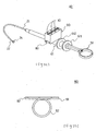
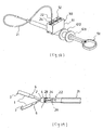
- a clipping equipment for biological tissues disclosed in Japanese Utility Model Application Laid-Open (JP-U) No.62-170010 is constructed of a clip 801 having opening habit, a clip securing ring 802 for closing a clip tip part, and a connecting plate 803 which is detachable on an operating wire in which a hook is attached to a tip (not shown), as shown in Fig. 35.
- this clipping equipment 800 for biological tissues when the clipping equipment holds a biological tissue such as a lesion, a connecting plate 803 is attached to a hook, an opened tip part of a clip 801 is pushed against a lesion with an endoscope, an operating wire positioned at a cavity of an operating member is pulled, thereby, a clip 801 is moved so that it is pulled into a clip securing ring 802, thereby, an opening part is closed to clip a lesion. And, since a clip 801 clips a lesion with an opening part on a tip side, a force directed to a basal direction of a clip 801 is exerted on a clip securing ring 802.
- a gel-like fixing agent 804 is filled into a clip securing ring 802.
- JP-A Japanese Patent Application Laid-Open (JP-A) No.50-75797 discloses a tissue clipping equipment for grasping a tissue in a body with a clip using an endoscope, and dwelling the clip therein. Since in this clipping equipment, a clip is directly mounted on a hook provided on a tip of an operating wire, there is a problem that, when a clip is dwelled, a clipping equipment must be moved forwardly and backwardly, and left and right in order to remove a clip from a hook, thus, a way to use it is troublesome.
- JP-U No. 2-6011 discloses a clipping equipment 900 which overcomes the aforementioned disadvantage, as shown in Fig. 36.
- This clipping equipment 900 is equipped with a hook 902 provided on a tip of an operating wire 901, and a connecting member 903 having an engaging pore 904 engaging with a pin 906 of a hook 902 on one end, and having a crook (not shown) which is connected to a clip and is deformable by stretching on the other end, wherein when a connecting plate 903 is moved to a hand side via an operating wire 901 in order to dwell a clip 905 in a biological tissue, a crook of a connecting plate 904 is stretched, and the engaging state of a clip 905 and a connecting plate 903 is released.
- this clipping equipment 900 improved troublesome operation of removing a clip from a hook
- a connecting plate 903 since a connecting plate 903 is engaged with an operating wire 901 also after clip dwelling, a connecting plate 903 must be removed after taken out from an endoscope, and there is a problem of disposal of a connecting plate 903 which has become an unnecessary part.
- a connecting plate 903 since a connecting plate 903 is small, it is sucked into a sucking port of an endoscope rarely, and this becomes a cause for worse suction.
- JP-U No.1-77703 shows a clipping equipment in which a ratchet mechanism consisting of an engaging claw and a claw to be engaged of a ratchet is applied.
- This clipping equipment is such that a pitch of a claw to be engaged is formed finer than that of an engaging claw, or at least two sets of an engaging claw and a claw to be engaged are disposed, and a phase of one of them is shifted without altering a pitch of a claw, and a moving pitch is small-sized as a whole, in which by pulling a wire fixing a clip, and opening a clip to a greatest degree and further pulling a wire, a clip is closed and, finally, a connecting plate is destructed, releasing a clip.
- a movement amount of an operating member can be operated finer by a ratchet mechanism.
- attachment of a clip and operation of opening are performed by a ratchet mechanism, there is a problem that, in order to assuredly stop a clip at an intended position, an operator must perform position adjusting operation while seeing a clip, and operation is troublesome.
- JP-A No.2000-335631 discloses a clip packaging body for an endoscope in which a clip for an endoscope can be accommodated between substrates.
- this endoscope packaging body when sterilization treatment is performed in a packaging body in advance, sterilization working becomes easy.
- Such the operation needs a skill and is troublesome.
- an object of the present invention is to provide a treating equipment clip for an endoscope which can assuredly clip a lesion over a long period of time, in ligating a bleeding site of a biological tissue, stitching a laceration, and marking in excision of a mucosal tissue with an endoscope.
- another object of the present invention is to provide a clipping equipment for a biological tissue which does not need seeing a degree of opening of a clip and does not need fine positioning adjustment.
- other object of the present invention is to provide a clipping equipment for a biological tissue which does not need troublesome operation for mounting and removing a clip.
- the present invention provides a clip comprising a self-opening clip body having a clipping part on a tip and provided with a twin-arm part extending from a basal part, and a securing ring, wherein the self-opening clip body has a first concave part on a clip basal part, and a second concave part between the first concave part and a clip tip part, respectively, the securing ring is mounted on the first concave part, and is sliding-moved from a mounting position of a first concave part with an external force to be mounted on a second concave part, thereby, said clip is used as a treating equipment for an endoscope of closing a clipping part at a tip of the clip body.
- the present invention provides a clipping equipment for a biological tissue equipped with an outer tube which can be inserted into a biological cavity, an operating member freely passed through the outer tube, an operating wire freely passed through the operating member, and a self-opening holder which can be opened and closed by the action of the operating member attached to a tip of the operating wire.
- the present invention provides a clip holder having one or two or more clip accommodating grooves for accommodating a clip comprising a self-opening clip body having a clipping part on a tip and equipped with a twin-arm part extending from a basal part, and a securing ring freely moving in a tip direction which is mounted in a concave part of the basal part, in the state where said clip is sunk with its tip facing downwardly.
- a tip side refers to a biological tissue side in the use state
- a basal side refers to a side opposite to a biological tissue.
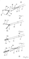
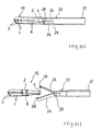
- a clip in an embodiment of the present invention will be explained by referring to Fig. 1 to Fig. 3.
- a clip 10 of the present example comprises a clip body 1 obtained by bending an elongate metal plate spring at a central part, and a cylindrical securing ring 2.
- a clip body 1 comprises clipping parts 3,3 for clipping a biological tissue on a tip, a basal part 4 exhibiting a generally U-shaped cross section, and twin-arm parts 11,11 having self-opening property on a tip which extend from a basal part 4. Since a metal plate spring constituting a clip body is movably inserted in a cavity of an operating member described later, a width size w thereof is restricted.
- a clip body 1 has a first concave part 5 on a basal part 4, and second concaves 6,6 between a first concave part 5 and a clip tip part, respectively, and a securing ring 2 is mounted on a first concave part 5.
- a site for mounting a first concave part 5 in a basal part such a position is preferable that a space in which a tip of a holder 8 can be hung on a generally U-shaped cross-sectional part 41 is possessed, and opening of a clip tip in the opened state cannot be narrowed.
- a site for mounting a second concave part 6 is not particularly limited as far as it is between a first concave part 5 and a clip tip part, and clipping parts 3,3 of a clip tip are tightly abutted thereagainst.
- a plate width ramp 69 on a tip side of a second concave part 6, and making a basal side from a ramp 69 a concave part when a securing ring 2 is sliding-moved from a mounting position in a first concave part 5 with an external force, it is assuredly mounted in a second concave part 6.
- a concave degree of a second concave part 6 of a clip body is larger than a concave degree of a first concave part 5 in that a securing ring 3 can be ensured.
- a tip part of a twin-arm part is bent inwardly and, at the same time, an irregular part is provided on its abutting surface in that a biological tissue can be tightly clipped.
- a holder 3 on a tip is usually opened as shown in Fig. 1 and, in this state, a securing ring 2 is mounted on a first concave part 5 of a basal part 4. Since a cavity part of a securing ring 2 is hung on a recess part, a securing ring 2 mounted in a first concave part 5 is not naturally moved forwardly and backwardly as far as an external force is exerted, and is not slipped on a tip side, not narrowing an opening width of a clipping part 3.
- Examples of a material for a clip include stainless steel, and titanium.
- a length of an arm part of a clip is not particularly limited, but is preferably 2.0 to 6.0mm, particularly preferably 3.0 to 5.0mm. When the length is within the aforementioned range, particularly, holding property of a clip is excellent.
- a pair of self-opening arm-like holders 8 which is attached to a tip of an operating wire 7 of a clipping equipment are hung on an internal side of a generally U-shaped cross sectional part 41 of a basal part 4 of a clip 1. Then, when an operating wire 7 which is in a cavity of an operating member 9 and can be moved forwardly and backwardly is pulled, holders 8 are pulled into a cavity of an operating member 9, and a securing ring 2 is abutted against a tip 91 of an operating member 9.
- a twin-arm part 11 of an clip body is gradually pulled into a cavity of a securing ring 2 from a basal part side of a clip and, when pulled until a position of a second concave part 6, a step 69 and a securing ring 2 are abutted, thereby, a securing ring 2 is stopped, clipping parts 3,3 at a tip of a clip body 1 are abutted into the state where a biological tissue (not shown) is clipped (Fig.2). Then, when an operating wire 7 is pushed in a direction opposite to pulling of an operating wire 7, that is, forwardly, a self-opening holder 8 is automatically come out from a basal part 4 of a clip.
- a securing ring 2 is fixed firm in a recess part of a second concave part 6, a clip body 1 in the closed state can assuredly clip a biological tissue to be clipped regardless of a size thereof, the tissue is not come out therefrom, and the state where a biological tissue is clipped can be maintained over a long period of time.
- a metal such as stainless steel and a titanium alloy, and a plastic such as an ABS resin, a rigid vinyl chloride resin, polyamide and polyethylene are preferable in that they are not corroded in a cavity, particularly, in stomach in which a digestion enzyme is secreted.
- a material rich in elasticity is preferable in that, upon clipping of a biological tissue, a clipping part 3 at a clip tip is brought into the closed state from the opened state, and is it necessary to retain the closed state for a long period of time.
- a material for a securing ring is not particularly limited, but the ring is used together with a clip body 1, and examples of the material include the same material as that of a clip body 1.
- a plastic such as fluorine resin, polyamine, and a silicone resin, and a metal such as stainless steel, and a titanium alloy are preferable.
- a biological tissue such as a lesion can be assuredly clipped over a long period of time.
- a clipping equipment for a biological tissues in the first embodiment of the present invention will be explained by referring to Fig.4 to Fig.10.
- a clipping equipment 20 for a biological tissue in an embodiment of the present example is equipped with an outer tube 21 which can be inserted into a biological cavity, an operating member 22 freely passed through the outer tube 21, an operating wire 23 freely passed though the opening member 22, a self-opening holder 24 which can be opened and closed by the action of the operating member attached to a tip of the operating wire 23, and a self-opening clip 10a having a clipping member for clipping a biological tissue which is attached to a tip of the holder 24 in a detachable manner by opening/closing the holder.
- a basal part of an operating wire 23 is connected to a handle (not shown).
- a material for an operating member 22 is not particularly limited, but examples include a thermoplastic resin such as polyether ether ketone, polyamide, and polyimide, and a thin metal coil.
- a thermoplastic resin is preferable in that it can assuredly transmit movement of an operating handle to a tip side, and a thin metal coil is preferable in that although a gap is formed by bending or pulling, bending property and rigidity are excellent.
- An external diameter of an operating member 22 is not particularly limited, but is preferably 1.7 to 2.7mm, particularly preferably 1.9 to 2.3mm.
- An operating wire 23 has a holder 24 fixed at a tip, and has a connecting part 25 having a slightly larger diameter that of a wire body which is equipped with a step 26.
- a stopper 27 through which an operating wire body can inserted and which is abutted against a step 26 is attached, preventing excessive protrusion of an operating member 22, and preventing a holder 24 from excessively entering an operating member 22.
- a material for an operating wire 23 is not particularly limited, but a material, a whole or a part of which has flexibility, is preferable. Specific examples include a metal wire such as stainless steel, and carbon steel, and a resin fiber such as polyamide, polyether, and ultra high molecular weight polyethylene.
- An outer tube 21 is a hollow continuous flexible member.
- An internal diameter of an external casing 21 is not particularly limited, but is preferably 1.8 to 2.8mm, particularly preferably 2.0 to 2.4mm. When an internal diameter is within the aforementioned range, operating property is particularly excellent.
- a length of an external casing 21 is not particularly limited, but is preferably 1,500 to 3,000mm, particularly preferably 1,600 to 2, 300mm. When the length is within the aforementioned range, operating property in an endoscope is particularly excellent.
- a material for an external case 21 is not particularly limited, but examples include a fluorine resin such as polytetrafluoroethylene (PTFE), and a tetrafluoroethylene-hexafluoropropylene copolymer resin (FEP).
- a clip 10a is not particularly limited as far as it is equipped with a self-opening twin-arm part 11a, and a securing ring 12 for closing a clipping part 15 of a twin-arm part 11a as shown in Fig.4, but a clip 10 shown in Fig.1 and Fig.2 is preferable.
- FIG. 4 A method of mounting a clip 10a in a clipping equipment 20 for a biological tissue by the aforementioned construction will be explained.
- an operating wire 23 is fixed at an operating handle and, by pulling an operating handle, an operating member 22 is moved on a holder 24 side in a direction of an axis line of an operating wire 23.
- a holder 24 consisting of a pair of arm parts enters a basal side while contacting with an internal circumferential surface of an operating member 22, therefore, is gradually being closed.
- a tip hook 28 of an operating member 22 is closed, clipping a basal part 14 of a clip 10a to retain a clip 10a.
- a securing ring 12 is abutted against a tip of an operating member 22, and then a securing ring 12 is abutted against a step 13 which is between both arm parts of a clip 10a, closing clipping parts 15,15 of a clip (Fig.6, Fig.9).
- a holder 24 is protruded from an operating member 22, self-opening property possessed by a holder 24 makes a pair of arm parts in the opened state, and a clip 10a while it is opened can be detached.
- a clipping equipment 20 for a biological tissue According to a clipping equipment 20 for a biological tissue, complicated operating is not necessary in mounting or detaching a clip.
- a clip 10a is retained by a holder 24, even if an operating member 22 is moved slightly, since a holder 24 is still accommodated in a cavity of an operating member 22, and tip hooks 28 are overlaid each other, a clip 10a is not easily fallen.
- a gap between tip hooks 28 is slightly opened, since a plate of a U-shaped cross section 41 of a basal part 4 of a clip 10a has an extent of a width, a clip 10a is not fallen from a holder 24.
- a shape of a holder 24 is not limited to the aforementioned generally V-letter shape, but for example, a generally U-letter shape 24a as shown in Fig.10 suffices.
- a load applied to a connecting part 25 accompanied with shape change can be dispersed, spring characteristic is improved and, further, a tip part can be closed more rapidly as compared with a linear-like state.
- any shape can be adopted in view of a time of opening and closing motion of a twin-arm part, and spring characteristic.
- a method of operating member 22 and an operating wire 23 is not limited to the aforementioned method, but examples include a method of fixing an operating wire 23, and moving an operating member 22, and a method of moving both of an operating wire 23 and an operating member 22.
- a clipping equipment 20 for a biological tissue since complicating procedure such as mounting and detachment of a clip is not necessary, the equipment is extremely useful as a clipping equipment for a biological tissue which is used in marking for making clear a region where treatment such as ligation and excision of a bleeding site of a biological tissue.
- a clipping equipment for a biological tissue in a second embodiment will be explained by referring to Fig.11 to Fig.23.
- description of a sliding cylinder 211 of Fig.11 is omitted.
- a clipping equipment 30 for a biological tissue of the present example the same symbol is added to the same component as that of the clipping equipment 20 for a biological tissue in the first embodiment example, explanation thereof is omitted, and different points will be mainly explained.
- a different point from a clip equipment 20 for a biological tissue is in that the equipment further has a handle 51 for controlling an operating member, and a first forcing mechanism for forwarding a handle 51 and, at the same time, stopping forwarding of a handle 51, a retaining mechanism for retaining a stoppage position of a handle 51 once, a second forcing mechanism for further forwarding from a stoppage position of a handle 51 and, at the same time, stopping forwarding of a handle, and a returning mechanism by which a handle 51 is automatically returned to a position before first forcing are provided.
- a clipping equipment 30 consists of an external casing 21, a hollow sliding cylinder 211 which is connected to an external casing 21 on a tip side, and provided with a connecting flange 213 on a basal side, an equipment body part 61 equipped with a main chamber in which a tip side part is fitted into a cavity of a sliding cylinder 211, a stopping means situated on a tip side which is mounted in a main chamber of an equipment body part 61 in the fixed state, a position retaining means 64 which is mounted in a main chamber adjacent to a stopping means 63 on a basal side in the fixed state, a handle 51 which is inserted into an equipment body part 61 from a basal side, and a bar-like member 71 in which one end on a basal side is abutted against a back of a substrate 651 of a rotation body 65, and the other end is protruded from a tip side of an equipment body part 61.
- a handle 51 consists of a ring-like clipping part 511, and a handle axis 512 in which one end is connected to a clipping part 511 and the other end is equipped with a crown-like first cam part 514.
- a clipping part 511 is operated by an operator by grasping with a hand, and has such an extent of a space that a finger of an operator can be inserted.
- a first cam part 514 is a ring-like projection having 6 triangular projections in which valley parts are formed every 60 degree on an end face of a cylindrical member.
- a first cam part 514 engages with three engaging feathers 653 of a rotation body 65 which moves in a stopping means 63 and in a position retaining means 64, and imparts a forwarding force and a rotating force to a rotation body 65.
- a connecting part of a ring-like clipping part 511 and a handle axis 512 there is a different form around a connecting part of a ring-like clipping part 511 and a handle axis 512.
- a position retaining means 64 is a cylindrical member which is fixed in a main chamber 615 of an equipment body part 61, determines a position of accommodation of a rotation body 65 in the state before operation, guides forwarding of a rotation body 65 by first forcing operation and, at the same time, leads a rotation body to a position of initiation of second forcing.
- a cam group 642 equipped with 6 saw blade cross section-shaped notches 645 is attached.
- a cam groove 642 imparts rotation of maximum 60 degree.
- An inclined surface of a notch 645 is formed as a descending inclination in a counterclock direction seen from a tip side.
- a stopping means 63 is a cylindrical member which is fixed adjacent to a tip side of a position retaining means 64 in a main chamber of an equipment body part 61, stops a entering rotation body 65 by first forcing operation and, at the same time, guides entrance of a rotation body 65 by second forcing operation.
- a stopping means 63 has three ribs 631 extending from a tip side to a midway in an axial direction on an internal circumferential surface (length of symbol m of Fig.22). Three ribs 631 are formed at an interval of 120 degree, and one rib is formed at a position at 50 degree counterclockwisely relative to a vertical axis seen from a tip side.
- a stopping means 63 is such that a tip opening is abutted against a wall of a main chamber in the state where it is disposed in a main chamber of an equipment body part 61. For this reason, a rotation body 65 is not protruded from a stopping means 63 in a tip direction.
- a length 1 of a stopping means 63 is a forwarding stroke of a rotation body 65.
- a rotation body 65 is fitted with a first cam part 514 at a tip of a handle axis, and is forwarded, retreated or rotated in a position retaining means 64 and a stopping means 63 to transmit an operating force to a bar-like member 71.
- a rotation body 65 has a substrate 651 positioned at a tip side which has notches 654 at a 120 degree pitch, and a second cam part 654 having one end on a basal side thereof of a sharp cross section shape with a plate-like feather member 653 which extends in an axial direction, at the same time, is attached at a 120 degree pitch between notches 654, on a substrate 651.
- the body has an engaging pore 655 with which a tip part 731 of a bar-like member 71 is engaged, on a center of a back of a substrate 651.
- a bar-like member 71 has a holder 24 attached at a tip, and is equipped with an operating wire 23 in which a basal end is fixed at a fixing ring part 73, an operating member 22 having a cavity in which an operating wire 23 is inserted, and having a regulating part 741 on a basal end, and a sliding short casing 75 in which a window part 751 is formed on an external circumferential surface of a cylindrical casing abutting with a regulating part 741 on a basal side.
- a basal part 751 of a sliding short casing 75 is engaged with an engaging pore 655 on a back of a substrate 651 of a rotating body.
- a fixing ring part 73 is fixed on a tip side slightly from a main chamber of an equipment body part 61, and is not interlocked with operation of a handle.
- a fixing ring part 73 of an operating wire 23 is slidably fitted in a window part 751 of a sliding short casing 75.
- An operating member 22 is forwarded against spring power of a spring 74 via a sliding short casing 75 by forwarding of a rotation body 65 (forwarding of a handle 51) and, when a rotation body 65 is retreated by spring power of a spring 74, the member is retreated interlocking therewith.
- An interior of an equipment body part 61 has, in an order from a tip side, a tip opening 616 in which an operating member 22 comes in and out, a chamber 614 for accommodating a spring 74, a fixing part 617 at which a fixing ring part 73 of a bar-like member is fixed, a main chamber 615 in which a stopping means 63 and a position retaining means 64 are accommodated, and an inserting port 616 in which a tip of a handle axis is inserted.
- a first flange part 611, and a second flange part 612 are attached to a cylindrical body from a basal side, to enhance operating property.
- a sliding cylinder 211 is a member for operating forwarding and retreating of a hollow external casing 21, and is a cylindrical entity which is fitted at a tip part of an equipment body part 611.
- a tip side is connected to a hollow external casing 21 which is inserted into a biological cavity, and a fixing flange 213 having a convex part (not shown) fitting in a concave part 613 of an equipment body part is provided on a basal side.
- An engagement releasing means 214 for releasing engagement between a slide cylinder 211 and an equipment body 61 is attached to a fixing flange 213.
- An operating member 22 is inserted into an external casing 21.
- a sliding cylinder 211 mounted on an equipment body part 61 is such that, when operation of pulling a handle 51 in the state where engagement with an equipment body part 61 is released, or forcing a sliding cylinder 21 therein is performed, an external casing 21 is forwarded to an operating member 22. Thereby, a twin-arm part of a clip 10a is closed, and can be transiently accommodated in an external casing 21 in the state where a clip 10a is closed. Thereby, when an external casing 21 is inserted into an endoscope, since a clip 10a is accommodated in an external casing 21, a forceps pore of an endoscope is not damaged.
- a method of operating a clipping equipment 30 comprises first forcing operation, retaining step, second forcing operation and returning step.
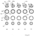
- first forcing operation when a handle 51 is pushed, a first cam part 514 at a tip of a handle and a second cam part 654 of a rotation body 65 are abutted (Fig.22 (a) and Fig.23 (a)).
- a first cam part 514 and a second cam part 654 are arranged so that mutual mountain-like top parts of cam parts are slightly slipped.
- a mountain-like top part 515 of a first cam part 514 at a tip of a handle is forwarded while abutting against a mountain-like inclination of a second cam part 654 of a rotation body.
- a rotation body 65 is forwarded from a position retaining means 64 to a stopping means 63.
- a rotation body 65 is retreated by an elastic force of a spring 74, and a second cam part of a rotation body 65 and a cam groove 642 of a position retaining means are engaged.
- a tip of a second cam part of a rotation part 65 is rotated from an original position by 60 degree counterclockwisely along with inclination of saw blade-like cam groove 642 (second rotation), and is stopped in a valley part of a cam groove 642 (Fig. 22(c) and Fig. 23(c)).
- a returning step after second forcing operation, when a hand is released from a handle 51, an operating member 22 is returned by elastic action of a spring 74 and, interlocking therewith, fitting between a rotation body 65, a feather member 653, and a rib 631 of a stopping means 63 is released, a tip of a rotation body 65 comes to a spiral cam groove 642, is further moved along with its inclination, and is stopped at a valley part, rotating from an original position by 120 degree counterclockwisely (forth rotation). In this state, a feather member 653 of a rotation body 65 and a groove 641 of a position retaining means 64 are positioned so that they are fitted. For this reason, a rotation body 65 is automatically returned to an original position.
- an operating method is not limited to the aforementioned method of fixing an operating wire 23, and moving an operating member 22 by seeing relatively, but by reversing a position of a spring, and directions of a rotation body, a stopping means, and a position retaining means, an operation member may be fixed, and an operating wire may be moved.
- an operating wire may be moved.
- multi-stage stoppage, and position retaining may be performed.
- a treatment time can be shortened.
- a tip of an endoscope treating equipment can be put in and out by a constant amount.
- a clipping equipment in accordance with a third embodiment will be explained by referring to Fig. 24 to Fig.31.
- a clipping equipment 40 in a third embodiment the same symbol is added to the same component as that of the clipping equipment 30 in a second embodiment, explanation thereof will be omitted, and different points will be mainly explained. That is, a different point from a clipping equipment 30 in a clipping equipment 40 is in that a clip retaining member 90 is attached to an external circumferential surface of an equipment body part 61 near a second flange 612.
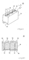
- a clip retaining member 90 is a block body 91, and has three of clip accommodating grooves 92 for accommodating a tip of a clip 10 downwardly in the sunk state, and generally cross grooves 94 consisting of guide grooves 93 which run straight through a center of an accommodating group 92, in a direction orthogonal with an accommodating groove 92.
- an engaging groove 94 which engages with a mounting equipment 80 is formed on a back of a block body 91.
- a clip accommodating groove 92 is slightly larger than a plate width of a twin-arm part 11, and is slightly wider from a deepest part towards a surface.
- a depth of a clip accommodating groove 92 is such a depth that a basal part is slightly seen in the state where a clip 10 is accommodated, and a groove length of clip accommodating groove 92 is slightly smaller than a width by which a clip 10 is opened in the natural state.
- a shape of a guide groove 93 is not particularly limited, but in the present example, by adopting an alloy-shaped groove when seen in a plane surface, a tip hook 28 of a holder 24 is easily guided to a generally U-shaped part 41 of a basal part of a clip.
- a guide groove 93 colored with a light emitting paint is preferable in that a guide groove 93 can be recognized even in a dark endoscope chamber.
- the number of clip accommodating grooves 92 which are formed into a block body 91 is 1, 2 or 4 or more in addition to the aforementioned 3.
- a material for a clip retaining member 90 is not particularly limited, but when a transparent material is used, this is preferable in that weather a clip 10 is accommodated or not can be observed from the outside.
- a transparent material examples include a resin material such as acrylonitrile ⁇ butadiene ⁇ styrene resin (ABS resin), polyethylene, polystyrene, polycarbonate, and acryl resin.
- ABS resin acrylonitrile ⁇ butadiene ⁇ styrene resin
- polyethylene polyethylene
- polystyrene polycarbonate
- acryl resin acrylonitrile ⁇ butadiene ⁇ styrene resin
- a mounting equipment 80 is an adapter for attaching a clip holding member 90 to a cylindrical body of an equipment body part 61.
- a mounting equipment 80 consists of a ring part 82 which is mounted on a equipment body part 61, and a plate-like engaging piece 82 which engages with an engaging groove 94 of a clip holding member 90 having a jaw part 82 provided above a ring part 82.
- a method of performing hemostasis using a clipping equipment 40 will be explained by referring to Fig. 28 to Fig. 31.
- description of a flange 213 of a sliding cylinder 211 is omitted.
- a clip holding member 90 is removed from a sterilized bag in the state where a clip 10 is accommodated in an accommodating groove 92, and is fixed to an equipment body part 61. While a tip part of an external casing 21 is grasped by a hand, a tip of a holder 24 is pushed against a guide groove 93 of a clip holding member 90. In this case, since a hand is not directly contacted with a clip 10, there is no fear of pollution.
- a clip 10 can be attached to a holder 24.
- a ring part 29 abutting against a securing ring 2 is provided.
- An external diameter of a ring part 29 is approximately the same as an external diameter of a securing ring 2, and a securing ring 2 can be forwarded by forwarding an operating member 22.
- a variation example of a clip holding member 90 will be explained by referring to Fig.32 to Fig.34.
- a clip holding member 90a the same symbol is added to the same component as that of a clip holding member 90, explanation thereof will be omitted, and different points will be mainly explained.
- a different point from a clip holding member 90 is a point in that the number of general cross grooves is one, a point in that a guide groove 93a is an inclination which runs straight passing through a center of an accommodating groove and descends towards a center, a depth at a central part of a guide groove is such that the central part is above a securing ring 2 in the state where a clip 10 is accommodated, and the holder is hung on a generally U-shaped basal part of the clip, and a point in that mounting is not on an external circumferential surface of an equipment body part 61, but on a separate member from a clipping equipment.
- Examples of a form of a guide groove 93 include a fan shape in addition to the aforementioned alloy shape and rectangular shape when seen on a plane surface.
- Fig.33 is a cross-sectional view of Fig.32
- Fig.34 is a view showing the state where a holder 24 is closed in Fig.33. A tip of a holder 24 is pushed against a guide groove 93a of a clip holding member 90a on which a clip 10 is mounted. In this state, by moving an operating member 22 to a clip holding member 90a side, the state where a clip 10 is held by a holder 24 is obtained (Fig.34). Then, a clip 10 is removed from a clip holding member 90a, and mounting of a clip 10 on a clipping equipment is completed.
- a clipping equipment 40 of a third embodiment example the same operation as that of a clipping equipment 30 of a second embodiment example is performed and, additionally, by simple operation of grasping a handle 51 by one hand, grasping an external casing 21 by the other hand, and forcing a tip of a holder 24 into a guide groove 93, a clip 10 can be attached to a holder 24. For this reason, even an operator who is not familiar with this operation can perform clip mounting operation simply and efficiently.
- the clip and the clipping equipment of the present invention are extremely useful as a treating equipment which is used in ligating a bleeding site of a biological tissue, stitching a laceration, and marking in excision of a mucosal tissue with an endoscope.
Landscapes
- Health & Medical Sciences (AREA)
- Surgery (AREA)
- Life Sciences & Earth Sciences (AREA)
- Heart & Thoracic Surgery (AREA)
- Nuclear Medicine, Radiotherapy & Molecular Imaging (AREA)
- Vascular Medicine (AREA)
- Engineering & Computer Science (AREA)
- Biomedical Technology (AREA)
- Reproductive Health (AREA)
- Medical Informatics (AREA)
- Molecular Biology (AREA)
- Animal Behavior & Ethology (AREA)
- General Health & Medical Sciences (AREA)
- Public Health (AREA)
- Veterinary Medicine (AREA)
- Surgical Instruments (AREA)
Priority Applications (1)
| Application Number | Priority Date | Filing Date | Title |
|---|---|---|---|
| EP12174707A EP2522283A3 (fr) | 2003-03-17 | 2004-03-16 | Agrafe et instrument d'agrafage pour tissus biologiques |
Applications Claiming Priority (11)
| Application Number | Priority Date | Filing Date | Title |
|---|---|---|---|
| JP2003072747 | 2003-03-17 | ||
| JP2003072747 | 2003-03-17 | ||
| JP2003073655 | 2003-03-18 | ||
| JP2003073655 | 2003-03-18 | ||
| JP2003190806 | 2003-07-03 | ||
| JP2003190806 | 2003-07-03 | ||
| JP2003309507 | 2003-09-02 | ||
| JP2003309507 | 2003-09-02 | ||
| JP2004061630 | 2004-03-05 | ||
| JP2004061630 | 2004-03-05 | ||
| PCT/JP2004/003468 WO2004082488A1 (fr) | 2003-03-17 | 2004-03-16 | Agrafe et instrument d'agrafage pour tissus biologiques |
Publications (2)
| Publication Number | Publication Date |
|---|---|
| EP1604614A1 true EP1604614A1 (fr) | 2005-12-14 |
| EP1604614A4 EP1604614A4 (fr) | 2010-03-10 |
Family
ID=33033327
Family Applications (2)
| Application Number | Title | Priority Date | Filing Date |
|---|---|---|---|
| EP04721011A Ceased EP1604614A4 (fr) | 2003-03-17 | 2004-03-16 | Agrafe et instrument d'agrafage pour tissus biologiques |
| EP12174707A Withdrawn EP2522283A3 (fr) | 2003-03-17 | 2004-03-16 | Agrafe et instrument d'agrafage pour tissus biologiques |
Family Applications After (1)
| Application Number | Title | Priority Date | Filing Date |
|---|---|---|---|
| EP12174707A Withdrawn EP2522283A3 (fr) | 2003-03-17 | 2004-03-16 | Agrafe et instrument d'agrafage pour tissus biologiques |
Country Status (5)
| Country | Link |
|---|---|
| US (2) | US20060259049A1 (fr) |
| EP (2) | EP1604614A4 (fr) |
| JP (1) | JP4502134B2 (fr) |
| KR (1) | KR101078544B1 (fr) |
| WO (1) | WO2004082488A1 (fr) |
Cited By (10)
| Publication number | Priority date | Publication date | Assignee | Title |
|---|---|---|---|---|
| WO2007142977A3 (fr) * | 2006-06-01 | 2008-05-29 | Wilson Cook Medical Inc | Mécanismes de libération d'un dispositif d'agrafe |
| US8152822B2 (en) | 2006-12-05 | 2012-04-10 | Cook Medical Technologies Llc | Combination therapy hemostatic clip |
| US8425412B2 (en) | 2006-07-14 | 2013-04-23 | Cook Medical Technologies Llc | Papilla spreader |
| US8764774B2 (en) | 2010-11-09 | 2014-07-01 | Cook Medical Technologies Llc | Clip system having tether segments for closure |
| EP2995262A4 (fr) * | 2013-05-07 | 2016-12-21 | Olympus Corp | Instrument de traitement endoscopique |
| US9662113B2 (en) | 2013-05-07 | 2017-05-30 | Olympus Corporation | Endoscope treatment tool |
| US9949740B2 (en) | 2013-05-07 | 2018-04-24 | Olympus Corporation | Clip unit |
| CN110769765A (zh) * | 2017-06-21 | 2020-02-07 | 富士胶片株式会社 | 夹具处置器具 |
| DE102022104089A1 (de) | 2022-02-22 | 2023-08-24 | FUJIFILM medwork GmbH | Medizinischer Clip und Vorrichtung zu dessen Applizierung in einem Gastrointestinaltrakt sowie Verfahren zur endoskopischen Applizierung eines Clips |
| CN116940286A (zh) * | 2021-03-31 | 2023-10-24 | 日本瑞翁株式会社 | 内窥镜用处置器具 |
Families Citing this family (177)
| Publication number | Priority date | Publication date | Assignee | Title |
|---|---|---|---|---|
| US8137364B2 (en) | 2003-09-11 | 2012-03-20 | Abbott Laboratories | Articulating suturing device and method |
| US6964668B2 (en) | 1999-03-04 | 2005-11-15 | Abbott Laboratories | Articulating suturing device and method |
| US6461364B1 (en) | 2000-01-05 | 2002-10-08 | Integrated Vascular Systems, Inc. | Vascular sheath with bioabsorbable puncture site closure apparatus and methods of use |
| US9579091B2 (en) | 2000-01-05 | 2017-02-28 | Integrated Vascular Systems, Inc. | Closure system and methods of use |
| US7842068B2 (en) | 2000-12-07 | 2010-11-30 | Integrated Vascular Systems, Inc. | Apparatus and methods for providing tactile feedback while delivering a closure device |
| US6391048B1 (en) | 2000-01-05 | 2002-05-21 | Integrated Vascular Systems, Inc. | Integrated vascular device with puncture site closure component and sealant and methods of use |
| JP2004508092A (ja) | 2000-09-08 | 2004-03-18 | コールマン ジェイムス イー | 外科用ステープラ |
| US6626918B1 (en) | 2000-10-06 | 2003-09-30 | Medical Technology Group | Apparatus and methods for positioning a vascular sheath |
| US8690910B2 (en) | 2000-12-07 | 2014-04-08 | Integrated Vascular Systems, Inc. | Closure device and methods for making and using them |
| US6623510B2 (en) | 2000-12-07 | 2003-09-23 | Integrated Vascular Systems, Inc. | Closure device and methods for making and using them |
| IES20010547A2 (en) | 2001-06-07 | 2002-12-11 | Christy Cummins | Surgical Staple |
| US6749621B2 (en) | 2002-02-21 | 2004-06-15 | Integrated Vascular Systems, Inc. | Sheath apparatus and methods for delivering a closure device |
| US8398656B2 (en) | 2003-01-30 | 2013-03-19 | Integrated Vascular Systems, Inc. | Clip applier and methods of use |
| US8905937B2 (en) | 2009-02-26 | 2014-12-09 | Integrated Vascular Systems, Inc. | Methods and apparatus for locating a surface of a body lumen |
| US8758398B2 (en) | 2006-09-08 | 2014-06-24 | Integrated Vascular Systems, Inc. | Apparatus and method for delivering a closure element |
| US8202293B2 (en) | 2003-01-30 | 2012-06-19 | Integrated Vascular Systems, Inc. | Clip applier and methods of use |
| US7462188B2 (en) * | 2003-09-26 | 2008-12-09 | Abbott Laboratories | Device and method for suturing intracardiac defects |
| IES20040368A2 (en) | 2004-05-25 | 2005-11-30 | James E Coleman | Surgical stapler |
| US7819886B2 (en) | 2004-10-08 | 2010-10-26 | Tyco Healthcare Group Lp | Endoscopic surgical clip applier |
| US8409222B2 (en) | 2004-10-08 | 2013-04-02 | Covidien Lp | Endoscopic surgical clip applier |
| JP4783372B2 (ja) | 2004-10-08 | 2011-09-28 | タイコ ヘルスケア グループ エルピー | 外科用クリップを付与するための装置 |
| JP5047799B2 (ja) | 2004-10-08 | 2012-10-10 | タイコ ヘルスケア グループ リミテッド パートナーシップ | 内視鏡外科用クリップ取付器 |
| US9763668B2 (en) | 2004-10-08 | 2017-09-19 | Covidien Lp | Endoscopic surgical clip applier |
| JP4758173B2 (ja) * | 2004-12-24 | 2011-08-24 | オリンパス株式会社 | 結紮装置 |
| US8926633B2 (en) | 2005-06-24 | 2015-01-06 | Abbott Laboratories | Apparatus and method for delivering a closure element |
| US8313497B2 (en) | 2005-07-01 | 2012-11-20 | Abbott Laboratories | Clip applier and methods of use |
| US8083754B2 (en) | 2005-08-08 | 2011-12-27 | Abbott Laboratories | Vascular suturing device with needle capture |
| US8920442B2 (en) | 2005-08-24 | 2014-12-30 | Abbott Vascular Inc. | Vascular opening edge eversion methods and apparatuses |
| US9456811B2 (en) | 2005-08-24 | 2016-10-04 | Abbott Vascular Inc. | Vascular closure methods and apparatuses |
| US8758397B2 (en) * | 2005-08-24 | 2014-06-24 | Abbott Vascular Inc. | Vascular closure methods and apparatuses |
| US20070060895A1 (en) * | 2005-08-24 | 2007-03-15 | Sibbitt Wilmer L Jr | Vascular closure methods and apparatuses |
| JP4935039B2 (ja) * | 2005-09-30 | 2012-05-23 | 住友ベークライト株式会社 | 内視鏡用クリップ |
| JP4935040B2 (ja) * | 2005-09-30 | 2012-05-23 | 住友ベークライト株式会社 | 内視鏡用クリップ |
| US8808310B2 (en) | 2006-04-20 | 2014-08-19 | Integrated Vascular Systems, Inc. | Resettable clip applier and reset tools |
| US8556930B2 (en) | 2006-06-28 | 2013-10-15 | Abbott Laboratories | Vessel closure device |
| EP1913881B1 (fr) | 2006-10-17 | 2014-06-11 | Covidien LP | Appareil pour l'application de pinces chirurgicales |
| US8382773B2 (en) | 2007-03-26 | 2013-02-26 | Covidien Lp | Endoscopic surgical clip applier |
| CA2682958C (fr) | 2007-04-11 | 2015-11-10 | Tyco Healthcare Group Lp | Applicateur d'agrafes chirurgicales |
| US8226681B2 (en) | 2007-06-25 | 2012-07-24 | Abbott Laboratories | Methods, devices, and apparatus for managing access through tissue |
| US8574244B2 (en) | 2007-06-25 | 2013-11-05 | Abbott Laboratories | System for closing a puncture in a vessel wall |
| JP5246393B2 (ja) * | 2007-11-28 | 2013-07-24 | 住友ベークライト株式会社 | 体外回収部品離脱用カートリッジ及び両用カートリッジ |
| JP5246394B2 (ja) * | 2007-11-28 | 2013-07-24 | 住友ベークライト株式会社 | クリップ、クリップユニット及びクリップ装置 |
| US8893947B2 (en) | 2007-12-17 | 2014-11-25 | Abbott Laboratories | Clip applier and methods of use |
| DE102008037314B3 (de) * | 2008-08-01 | 2010-03-04 | Otto-Von-Guericke-Universität Magdeburg Medizinische Fakultät | Markierungsklipp für einen Bereich der Magen- oder Darminnenwand |
| US20110208212A1 (en) | 2010-02-19 | 2011-08-25 | Zergiebel Earl M | Surgical clip applier |
| US8056565B2 (en) | 2008-08-25 | 2011-11-15 | Tyco Healthcare Group Lp | Surgical clip applier and method of assembly |
| US8465502B2 (en) | 2008-08-25 | 2013-06-18 | Covidien Lp | Surgical clip applier and method of assembly |
| US9358015B2 (en) | 2008-08-29 | 2016-06-07 | Covidien Lp | Endoscopic surgical clip applier with wedge plate |
| US8267944B2 (en) | 2008-08-29 | 2012-09-18 | Tyco Healthcare Group Lp | Endoscopic surgical clip applier with lock out |
| US8585717B2 (en) | 2008-08-29 | 2013-11-19 | Covidien Lp | Single stroke endoscopic surgical clip applier |
| US8409223B2 (en) | 2008-08-29 | 2013-04-02 | Covidien Lp | Endoscopic surgical clip applier with clip retention |
| US9486191B2 (en) | 2009-01-09 | 2016-11-08 | Abbott Vascular, Inc. | Closure devices |
| KR101263937B1 (ko) * | 2009-06-29 | 2013-05-13 | 국립암센터 | 수술용 형광 표시 클립 |
| USD605031S1 (en) * | 2009-08-03 | 2009-12-01 | Kristopher Schmittgens | Conduit support |
| US9089391B2 (en) * | 2009-08-24 | 2015-07-28 | Cvdevices, Llc | Tissue restoration devices, systems, and methods |
| US8734469B2 (en) | 2009-10-13 | 2014-05-27 | Covidien Lp | Suture clip applier |
| US9186136B2 (en) | 2009-12-09 | 2015-11-17 | Covidien Lp | Surgical clip applier |
| US8545486B2 (en) | 2009-12-15 | 2013-10-01 | Covidien Lp | Surgical clip applier |
| US8491611B2 (en) * | 2009-12-18 | 2013-07-23 | DePuy Synthes Products, LLC. | Neural tissue retraction and preservation device |
| KR101159422B1 (ko) * | 2009-12-22 | 2012-06-28 | 국립암센터 | 수술용 표시자 클립 및 클립 장치 |
| US8403945B2 (en) | 2010-02-25 | 2013-03-26 | Covidien Lp | Articulating endoscopic surgical clip applier |
| KR101110597B1 (ko) * | 2010-04-19 | 2012-02-15 | 이세동 | 치료용 클립, 클립 유닛 및 클립 장치 |
| US8403946B2 (en) | 2010-07-28 | 2013-03-26 | Covidien Lp | Articulating clip applier cartridge |
| US8968337B2 (en) | 2010-07-28 | 2015-03-03 | Covidien Lp | Articulating clip applier |
| US9370353B2 (en) | 2010-09-01 | 2016-06-21 | Abbott Cardiovascular Systems, Inc. | Suturing devices and methods |
| US9011464B2 (en) | 2010-11-02 | 2015-04-21 | Covidien Lp | Self-centering clip and jaw |
| US9186153B2 (en) | 2011-01-31 | 2015-11-17 | Covidien Lp | Locking cam driver and jaw assembly for clip applier |
| US9149276B2 (en) | 2011-03-21 | 2015-10-06 | Abbott Cardiovascular Systems, Inc. | Clip and deployment apparatus for tissue closure |
| US8568408B2 (en) * | 2011-04-21 | 2013-10-29 | Covidien Lp | Surgical forceps |
| US9775623B2 (en) | 2011-04-29 | 2017-10-03 | Covidien Lp | Surgical clip applier including clip relief feature |
| US9414822B2 (en) | 2011-05-19 | 2016-08-16 | Abbott Cardiovascular Systems, Inc. | Tissue eversion apparatus and tissue closure device and methods for use thereof |
| EP2755567B1 (fr) * | 2011-09-15 | 2018-03-07 | I.B.I Israel Biomedical Innovations Ltd. | Organe de fixation chirurgical ayant un élément de verrouillage par encliquetage et dispositifs le déployant |
| US20130131697A1 (en) | 2011-11-21 | 2013-05-23 | Covidien Lp | Surgical clip applier |
| US9078645B2 (en) * | 2011-12-19 | 2015-07-14 | Edwards Lifesciences Corporation | Knotless suture anchoring devices and tools for implants |
| US9364239B2 (en) | 2011-12-19 | 2016-06-14 | Covidien Lp | Jaw closure mechanism for a surgical clip applier |
| US9364216B2 (en) | 2011-12-29 | 2016-06-14 | Covidien Lp | Surgical clip applier with integrated clip counter |
| US20130245653A1 (en) * | 2012-03-19 | 2013-09-19 | Craig Michael Litherland | Zero artifact vascular clip method and apparatus |
| US8858573B2 (en) | 2012-04-10 | 2014-10-14 | Abbott Cardiovascular Systems, Inc. | Apparatus and method for suturing body lumens |
| US9408610B2 (en) | 2012-05-04 | 2016-08-09 | Covidien Lp | Surgical clip applier with dissector |
| US9241707B2 (en) | 2012-05-31 | 2016-01-26 | Abbott Cardiovascular Systems, Inc. | Systems, methods, and devices for closing holes in body lumens |
| US9532787B2 (en) | 2012-05-31 | 2017-01-03 | Covidien Lp | Endoscopic clip applier |
| US9364209B2 (en) | 2012-12-21 | 2016-06-14 | Abbott Cardiovascular Systems, Inc. | Articulating suturing device |
| US9113892B2 (en) | 2013-01-08 | 2015-08-25 | Covidien Lp | Surgical clip applier |
| US9968362B2 (en) | 2013-01-08 | 2018-05-15 | Covidien Lp | Surgical clip applier |
| US9750500B2 (en) | 2013-01-18 | 2017-09-05 | Covidien Lp | Surgical clip applier |
| NZ710444A (en) | 2013-02-11 | 2020-08-28 | Univ California | Compositions and methods for treating neurodegenerative diseases and cardiomyopathy |
| US8986330B2 (en) | 2013-07-12 | 2015-03-24 | Miami Instruments Llc | Aortic cross clamp |
| US9775624B2 (en) | 2013-08-27 | 2017-10-03 | Covidien Lp | Surgical clip applier |
| JP6716453B2 (ja) * | 2014-03-31 | 2020-07-01 | 日本ゼオン株式会社 | 内視鏡用処置具 |
| JP6233147B2 (ja) * | 2014-03-31 | 2017-11-22 | 日本ゼオン株式会社 | 留置スネア用結紮装置 |
| KR101601682B1 (ko) | 2014-07-18 | 2016-03-09 | 금오공과대학교 산학협력단 | 인체 수술용 위치 표시 장치 |
| KR101601678B1 (ko) | 2014-07-18 | 2016-03-09 | 금오공과대학교 산학협력단 | 인체 수술용 위치 표시 장치 |
| US10441292B2 (en) | 2014-10-24 | 2019-10-15 | Kaneka Corporation | Clip device for endoscope |
| US10702278B2 (en) | 2014-12-02 | 2020-07-07 | Covidien Lp | Laparoscopic surgical ligation clip applier |
| US9931124B2 (en) | 2015-01-07 | 2018-04-03 | Covidien Lp | Reposable clip applier |
| WO2016112509A1 (fr) | 2015-01-15 | 2016-07-21 | Covidien Lp | Applicateur d'agrafes chirurgicales endoscopique réutilisable |
| US10292712B2 (en) | 2015-01-28 | 2019-05-21 | Covidien Lp | Surgical clip applier with integrated cutter |
| US10159491B2 (en) | 2015-03-10 | 2018-12-25 | Covidien Lp | Endoscopic reposable surgical clip applier |
| US9808892B2 (en) * | 2015-06-05 | 2017-11-07 | Shelley L. Dowden | Fitting holding device |
| JP6694893B2 (ja) * | 2015-10-23 | 2020-05-20 | 株式会社カネカ | 医療用クリップ |
| CA2998890A1 (fr) | 2015-11-03 | 2017-05-11 | Covidien Lp | Applicateur endoscopique d'agrafes chirurgicales |
| US10390831B2 (en) | 2015-11-10 | 2019-08-27 | Covidien Lp | Endoscopic reposable surgical clip applier |
| CN108348261B (zh) | 2015-11-10 | 2021-03-16 | 柯惠有限合伙公司 | 可重复使用的内窥镜外科手术施夹器 |
| US10905425B2 (en) | 2015-11-10 | 2021-02-02 | Covidien Lp | Endoscopic reposable surgical clip applier |
| AU2016386597A1 (en) | 2016-01-11 | 2018-07-05 | Covidien Lp | Endoscopic reposable surgical clip applier |
| JP6634521B2 (ja) | 2016-01-18 | 2020-01-22 | コヴィディエン リミテッド パートナーシップ | 内視鏡外科用クリップアプライヤ |
| CA2958160A1 (fr) | 2016-02-24 | 2017-08-24 | Covidien Lp | Applicateur de pince chirurgicale reposable endoscopique |
| AU2017254659B2 (en) * | 2016-04-21 | 2022-10-06 | Zenflow, Inc. | Systems and methods for implants and deployment devices |
| WO2018008153A1 (fr) * | 2016-07-08 | 2018-01-11 | 有限会社ハヌマット | Procédé de détermination de la possibilité de début d'un cancer du côlon |
| WO2018027788A1 (fr) | 2016-08-11 | 2018-02-15 | Covidien Lp | Applicateur endoscopique d'agrafes chirurgicales et systèmes d'application d'agrafes |
| EP3503819A4 (fr) | 2016-08-25 | 2020-04-22 | Covidien LP | Applicateur d'agrafes chirurgicales endoscopiques et systèmes d'application d'agrafes |
| US10939905B2 (en) * | 2016-08-26 | 2021-03-09 | Edwards Lifesciences Corporation | Suture clips, deployment devices therefor, and methods of use |
| EP3520717B1 (fr) * | 2016-09-30 | 2021-05-05 | Zeon Corporation | Dispositif de retrait de clip |
| US10639044B2 (en) | 2016-10-31 | 2020-05-05 | Covidien Lp | Ligation clip module and clip applier |
| US10660651B2 (en) | 2016-10-31 | 2020-05-26 | Covidien Lp | Endoscopic reposable surgical clip applier |
| US10492795B2 (en) | 2016-11-01 | 2019-12-03 | Covidien Lp | Endoscopic surgical clip applier |
| US10426489B2 (en) | 2016-11-01 | 2019-10-01 | Covidien Lp | Endoscopic reposable surgical clip applier |
| US10610236B2 (en) | 2016-11-01 | 2020-04-07 | Covidien Lp | Endoscopic reposable surgical clip applier |
| KR101860226B1 (ko) * | 2016-11-10 | 2018-05-21 | 고려대학교 산학협력단 | 조직 고정장치 |
| JP7091335B2 (ja) | 2016-12-09 | 2022-06-27 | ゼンフロー, インコーポレイテッド | 尿道前立腺部内のインプラントの正確な展開のためのシステム、デバイス、および方法 |
| US10709455B2 (en) | 2017-02-02 | 2020-07-14 | Covidien Lp | Endoscopic surgical clip applier |
| US10758244B2 (en) | 2017-02-06 | 2020-09-01 | Covidien Lp | Endoscopic surgical clip applier |
| AU2017397500A1 (en) | 2017-02-06 | 2019-07-11 | Covidien Lp | Surgical clip applier with user feedback feature |
| US10660725B2 (en) | 2017-02-14 | 2020-05-26 | Covidien Lp | Endoscopic surgical clip applier including counter assembly |
| US10603038B2 (en) | 2017-02-22 | 2020-03-31 | Covidien Lp | Surgical clip applier including inserts for jaw assembly |
| US11583291B2 (en) | 2017-02-23 | 2023-02-21 | Covidien Lp | Endoscopic surgical clip applier |
| US10548602B2 (en) | 2017-02-23 | 2020-02-04 | Covidien Lp | Endoscopic surgical clip applier |
| US10675043B2 (en) | 2017-05-04 | 2020-06-09 | Covidien Lp | Reposable multi-fire surgical clip applier |
| US10722235B2 (en) | 2017-05-11 | 2020-07-28 | Covidien Lp | Spring-release surgical clip |
| US10639032B2 (en) | 2017-06-30 | 2020-05-05 | Covidien Lp | Endoscopic surgical clip applier including counter assembly |
| US10660723B2 (en) | 2017-06-30 | 2020-05-26 | Covidien Lp | Endoscopic reposable surgical clip applier |
| US10675112B2 (en) | 2017-08-07 | 2020-06-09 | Covidien Lp | Endoscopic surgical clip applier including counter assembly |
| US10863992B2 (en) | 2017-08-08 | 2020-12-15 | Covidien Lp | Endoscopic surgical clip applier |
| US10932790B2 (en) | 2017-08-08 | 2021-03-02 | Covidien Lp | Geared actuation mechanism and surgical clip applier including the same |
| US10786262B2 (en) | 2017-08-09 | 2020-09-29 | Covidien Lp | Endoscopic reposable surgical clip applier |
| US10786263B2 (en) | 2017-08-15 | 2020-09-29 | Covidien Lp | Endoscopic reposable surgical clip applier |
| US10835341B2 (en) | 2017-09-12 | 2020-11-17 | Covidien Lp | Endoscopic surgical clip applier and handle assemblies for use therewith |
| US10835260B2 (en) | 2017-09-13 | 2020-11-17 | Covidien Lp | Endoscopic surgical clip applier and handle assemblies for use therewith |
| US10758245B2 (en) | 2017-09-13 | 2020-09-01 | Covidien Lp | Clip counting mechanism for surgical clip applier |
| US10653429B2 (en) | 2017-09-13 | 2020-05-19 | Covidien Lp | Endoscopic surgical clip applier |
| US10828036B2 (en) | 2017-11-03 | 2020-11-10 | Covidien Lp | Endoscopic surgical clip applier and handle assemblies for use therewith |
| US10945734B2 (en) | 2017-11-03 | 2021-03-16 | Covidien Lp | Rotation knob assemblies and surgical instruments including the same |
| US11116513B2 (en) | 2017-11-03 | 2021-09-14 | Covidien Lp | Modular surgical clip cartridge |
| US10932791B2 (en) | 2017-11-03 | 2021-03-02 | Covidien Lp | Reposable multi-fire surgical clip applier |
| US11376015B2 (en) | 2017-11-03 | 2022-07-05 | Covidien Lp | Endoscopic surgical clip applier and handle assemblies for use therewith |
| KR102115491B1 (ko) * | 2017-11-20 | 2020-05-26 | 주식회사 파인메딕스 | 내시경용 클립장치 |
| US10722236B2 (en) | 2017-12-12 | 2020-07-28 | Covidien Lp | Endoscopic reposable surgical clip applier |
| US10743887B2 (en) | 2017-12-13 | 2020-08-18 | Covidien Lp | Reposable multi-fire surgical clip applier |
| US10959737B2 (en) | 2017-12-13 | 2021-03-30 | Covidien Lp | Reposable multi-fire surgical clip applier |
| US10849630B2 (en) | 2017-12-13 | 2020-12-01 | Covidien Lp | Reposable multi-fire surgical clip applier |
| US11051827B2 (en) | 2018-01-16 | 2021-07-06 | Covidien Lp | Endoscopic surgical instrument and handle assemblies for use therewith |
| EP3777718B1 (fr) * | 2018-03-30 | 2025-03-05 | Zeon Corporation | Attache à demeure |
| US10993721B2 (en) | 2018-04-25 | 2021-05-04 | Covidien Lp | Surgical clip applier |
| US10786273B2 (en) | 2018-07-13 | 2020-09-29 | Covidien Lp | Rotation knob assemblies for handle assemblies |
| US11259887B2 (en) | 2018-08-10 | 2022-03-01 | Covidien Lp | Feedback mechanisms for handle assemblies |
| US11253267B2 (en) | 2018-08-13 | 2022-02-22 | Covidien Lp | Friction reduction mechanisms for handle assemblies |
| US11033256B2 (en) | 2018-08-13 | 2021-06-15 | Covidien Lp | Linkage assembly for reusable surgical handle assemblies |
| US11344316B2 (en) | 2018-08-13 | 2022-05-31 | Covidien Lp | Elongated assemblies for surgical clip appliers and surgical clip appliers incorporating the same |
| US11219463B2 (en) | 2018-08-13 | 2022-01-11 | Covidien Lp | Bilateral spring for surgical instruments and surgical instruments including the same |
| US11051828B2 (en) | 2018-08-13 | 2021-07-06 | Covidien Lp | Rotation knob assemblies and surgical instruments including same |
| US11278267B2 (en) | 2018-08-13 | 2022-03-22 | Covidien Lp | Latch assemblies and surgical instruments including the same |
| US11246601B2 (en) | 2018-08-13 | 2022-02-15 | Covidien Lp | Elongated assemblies for surgical clip appliers and surgical clip appliers incorporating the same |
| KR101977581B1 (ko) * | 2018-08-30 | 2019-09-03 | 주식회사 파인메딕스 | 병변 위치 마킹용 클립을 포함하는 병변 위치 추적 시스템 |
| US11147566B2 (en) | 2018-10-01 | 2021-10-19 | Covidien Lp | Endoscopic surgical clip applier |
| CN109833074A (zh) * | 2019-02-20 | 2019-06-04 | 江苏格里特医疗科技有限公司 | 一种可旋转止血夹 |
| US11524398B2 (en) | 2019-03-19 | 2022-12-13 | Covidien Lp | Gear drive mechanisms for surgical instruments |
| JP7261897B2 (ja) * | 2019-11-01 | 2023-04-20 | オリンパス株式会社 | クリップデバイス |
| US11610702B2 (en) * | 2019-12-11 | 2023-03-21 | The Boeing Company | Temporary holder for transferring end of wire between end effectors |
| US11779340B2 (en) | 2020-01-02 | 2023-10-10 | Covidien Lp | Ligation clip loading device |
| US11723669B2 (en) | 2020-01-08 | 2023-08-15 | Covidien Lp | Clip applier with clip cartridge interface |
| US12114866B2 (en) | 2020-03-26 | 2024-10-15 | Covidien Lp | Interoperative clip loading device |
| WO2021210091A1 (fr) * | 2020-04-15 | 2021-10-21 | オリンパス株式会社 | Dispositif de traitement |
| CN114652386B (zh) | 2020-12-23 | 2026-03-13 | 奥林巴斯株式会社 | 夹具输送装置 |
| JPWO2022210174A1 (fr) | 2021-03-31 | 2022-10-06 | ||
| US20230233201A1 (en) * | 2022-01-24 | 2023-07-27 | Covidien Lp | Apparatus and method for endoscopically closing gastrointestinal defects |
| KR102441389B1 (ko) * | 2022-01-28 | 2022-09-13 | 유정선 | 내시경용 지혈클립 |
| US12419648B2 (en) | 2022-09-26 | 2025-09-23 | Covidien Lp | Two-part fasteners for surgical clip appliers and surgical clip appliers for deploying the same |
Family Cites Families (30)
| Publication number | Priority date | Publication date | Assignee | Title |
|---|---|---|---|---|
| JPS5626033B2 (fr) | 1973-11-07 | 1981-06-16 | ||
| US4076120A (en) * | 1976-12-10 | 1978-02-28 | American Hospital Supply Corporation | Cartridge for holding hemostatic clips |
| US4681107A (en) * | 1985-12-31 | 1987-07-21 | Kees Surgical Specialty Co. | Device for holding an aneurysm clip |
| JPS62170010A (ja) | 1986-01-22 | 1987-07-27 | Hitachi Ltd | 薄膜磁気ヘツドの製造方法 |
| JPS62170010U (fr) | 1986-04-18 | 1987-10-28 | ||
| US5366459A (en) * | 1987-05-14 | 1994-11-22 | Inbae Yoon | Surgical clip and clip application procedures |
| JPS6477703A (en) | 1987-09-18 | 1989-03-23 | Toshiba Corp | Measuring instrument for clearance at rotor blade top edge in axial-flow fluidic machine |
| JPH0511842Y2 (fr) | 1987-11-13 | 1993-03-25 | ||
| JPH026011A (ja) | 1988-06-24 | 1990-01-10 | Kobe Steel Ltd | 線引用ダイス |
| JPH0426091Y2 (fr) | 1988-06-24 | 1992-06-23 | ||
| GB2226245A (en) * | 1988-11-18 | 1990-06-27 | Alan Crockard | Endoscope, remote actuator and aneurysm clip applicator. |
| US5569274A (en) * | 1993-02-22 | 1996-10-29 | Heartport, Inc. | Endoscopic vascular clamping system and method |
| DE4319829C1 (de) * | 1993-06-16 | 1994-08-25 | Lerch Karl Dieter | Set zur Behandlung von Gefäßmißbildungen |
| JPH0819548A (ja) * | 1994-07-08 | 1996-01-23 | Olympus Optical Co Ltd | 大腸粘膜用のクリップ装置 |
| DE69517153T2 (de) * | 1994-11-02 | 2001-02-01 | Olympus Optical Co., Ltd. | Mit endoskop funktionierendes instrument |
| DE19534322A1 (de) * | 1995-09-15 | 1997-03-20 | Aesculap Ag | Chirurgischer Clip, insbesondere Gefäßclip |
| US5634932A (en) * | 1995-10-10 | 1997-06-03 | Industrial & Scientific Designs, Ltd. | Cantilever aneurysm clip system |
| JP3776529B2 (ja) * | 1996-02-29 | 2006-05-17 | オリンパス株式会社 | クリップ装置 |
| GB9722203D0 (en) | 1997-10-21 | 1997-12-17 | Univ London | Surgical clip |
| JP2000015988A (ja) * | 1998-07-07 | 2000-01-18 | Pilot Corp | ノック式筆記具 |
| JP4022022B2 (ja) | 1999-05-28 | 2007-12-12 | オリンパス株式会社 | 内視鏡用クリップ包装体およびその包装箱 |
| JP4472217B2 (ja) * | 2000-10-16 | 2010-06-02 | オリンパス株式会社 | 生体組織のクリップ装置 |
| JP2002224124A (ja) * | 2001-02-06 | 2002-08-13 | Olympus Optical Co Ltd | 結紮装置 |
| DE10334083A1 (de) * | 2003-07-26 | 2005-02-24 | Carl Stahl Gmbh | Verfahren und Vorrichtung zur endoskopischen Applizierung von sich schließenden medizinischen Clips |
| US8080021B2 (en) * | 2005-01-11 | 2011-12-20 | Boston Scientific Scimed, Inc. | Multiple clip deployment magazine |
| US8088161B2 (en) * | 2005-07-28 | 2012-01-03 | Visioncare Ophthalmic Technologies Inc. | Compressed haptics |
| US20070050023A1 (en) * | 2005-08-29 | 2007-03-01 | Bausch & Lomb Incorporated | Preloaded injector for intraocular lenses and methods of making and using |
| US8152822B2 (en) * | 2006-12-05 | 2012-04-10 | Cook Medical Technologies Llc | Combination therapy hemostatic clip |
| US8162959B2 (en) * | 2007-05-03 | 2012-04-24 | Boston Scientific Scimed, Inc. | Single stage hemostasis clipping device |
| JP2008307168A (ja) * | 2007-06-13 | 2008-12-25 | Hoya Corp | 内視鏡用クリップ装置 |
-
2004
- 2004-03-16 US US10/548,835 patent/US20060259049A1/en not_active Abandoned
- 2004-03-16 EP EP04721011A patent/EP1604614A4/fr not_active Ceased
- 2004-03-16 WO PCT/JP2004/003468 patent/WO2004082488A1/fr not_active Ceased
- 2004-03-16 KR KR1020057017392A patent/KR101078544B1/ko not_active Expired - Fee Related
- 2004-03-16 JP JP2005503687A patent/JP4502134B2/ja not_active Expired - Lifetime
- 2004-03-16 EP EP12174707A patent/EP2522283A3/fr not_active Withdrawn
-
2009
- 2009-07-10 US US12/500,884 patent/US8419751B2/en not_active Expired - Fee Related
Cited By (15)
| Publication number | Priority date | Publication date | Assignee | Title |
|---|---|---|---|---|
| WO2007142977A3 (fr) * | 2006-06-01 | 2008-05-29 | Wilson Cook Medical Inc | Mécanismes de libération d'un dispositif d'agrafe |
| US8425412B2 (en) | 2006-07-14 | 2013-04-23 | Cook Medical Technologies Llc | Papilla spreader |
| US8152822B2 (en) | 2006-12-05 | 2012-04-10 | Cook Medical Technologies Llc | Combination therapy hemostatic clip |
| US8764774B2 (en) | 2010-11-09 | 2014-07-01 | Cook Medical Technologies Llc | Clip system having tether segments for closure |
| US9687248B2 (en) | 2013-05-07 | 2017-06-27 | Olympus Corporation | Endoscope treatment tool |
| US9662113B2 (en) | 2013-05-07 | 2017-05-30 | Olympus Corporation | Endoscope treatment tool |
| EP2995262A4 (fr) * | 2013-05-07 | 2016-12-21 | Olympus Corp | Instrument de traitement endoscopique |
| US9949740B2 (en) | 2013-05-07 | 2018-04-24 | Olympus Corporation | Clip unit |
| US10842500B2 (en) | 2013-05-07 | 2020-11-24 | Olympus Corporation | Clip unit |
| CN110769765A (zh) * | 2017-06-21 | 2020-02-07 | 富士胶片株式会社 | 夹具处置器具 |
| EP3643253A4 (fr) * | 2017-06-21 | 2020-05-27 | Fujifilm Corporation | Instrument médical à pince |
| US11013517B2 (en) | 2017-06-21 | 2021-05-25 | Fujifilm Corporation | Clip treatment tool |
| CN116940286A (zh) * | 2021-03-31 | 2023-10-24 | 日本瑞翁株式会社 | 内窥镜用处置器具 |
| EP4316388A4 (fr) * | 2021-03-31 | 2025-03-26 | Zeon Corporation | Outil de traitement endoscopique |
| DE102022104089A1 (de) | 2022-02-22 | 2023-08-24 | FUJIFILM medwork GmbH | Medizinischer Clip und Vorrichtung zu dessen Applizierung in einem Gastrointestinaltrakt sowie Verfahren zur endoskopischen Applizierung eines Clips |
Also Published As
| Publication number | Publication date |
|---|---|
| KR20050110013A (ko) | 2005-11-22 |
| EP1604614A4 (fr) | 2010-03-10 |
| WO2004082488A1 (fr) | 2004-09-30 |
| US20090275958A1 (en) | 2009-11-05 |
| US8419751B2 (en) | 2013-04-16 |
| KR101078544B1 (ko) | 2011-11-01 |
| EP2522283A2 (fr) | 2012-11-14 |
| JPWO2004082488A1 (ja) | 2006-06-22 |
| JP4502134B2 (ja) | 2010-07-14 |
| EP2522283A3 (fr) | 2012-11-28 |
| US20060259049A1 (en) | 2006-11-16 |
Similar Documents
| Publication | Publication Date | Title |
|---|---|---|
| US8419751B2 (en) | Clip and clipping instrument for biological tissues | |
| CN100464716C (zh) | 生物体组织的夹钳装置 | |
| EP3328295B1 (fr) | Cartouche d'agrafe chirurgicale à encliquetage | |
| CN103519865B (zh) | 一种用于结扎夹的自动结扎钳 | |
| US20050240219A1 (en) | Peripheral vascular occlusion devices | |
| JP4242614B2 (ja) | 生体組織の結紮装置 | |
| JPWO2018235402A1 (ja) | クリップ処置具 | |
| CA3006664C (fr) | Assemblage de machoire destine a un outil chirurgical et element de collecte d'echantillon par biopsie | |
| CN203506827U (zh) | 一种用于结扎夹的自动结扎钳 | |
| JP2009022776A (ja) | 生体組織の結紮装置 | |
| JP4976297B2 (ja) | 外科用クリップ供給装置 | |
| US7942896B2 (en) | Forceps and collection assembly and related methods of use and manufacture | |
| JP4133969B2 (ja) | クリップおよびクリップ装置 | |
| CA2194775A1 (fr) | Ensemble effecteur terminal guide par un canal | |
| JP4813531B2 (ja) | 生体組織の結紮装置 | |
| JP4755234B2 (ja) | 生体組織の結紮装置 | |
| JP2012196376A (ja) | 内視鏡クリップ | |
| JP2009022777A (ja) | 生体組織の結紮装置 | |
| JP2007275386A (ja) | 医療用把持鉗子 | |
| CN213156295U (zh) | 一种穿刺器锁紧装置及手术机器人 | |
| EP1512377A1 (fr) | Dispositif de manipulation des fils, par exemple des ligatures | |
| JP2025056846A (ja) | スライド穿刺型クリップ | |
| JP2006271717A (ja) | 生体組織結紮装置 |
Legal Events
| Date | Code | Title | Description |
|---|---|---|---|
| PUAI | Public reference made under article 153(3) epc to a published international application that has entered the european phase |
Free format text: ORIGINAL CODE: 0009012 |
|
| 17P | Request for examination filed |
Effective date: 20050909 |
|
| AK | Designated contracting states |
Kind code of ref document: A1 Designated state(s): AT BE BG CH CY CZ DE DK EE ES FI FR GB GR HU IE IT LI LU MC NL PL PT RO SE SI SK TR |
|
| AX | Request for extension of the european patent |
Extension state: AL LT LV MK |
|
| DAX | Request for extension of the european patent (deleted) | ||
| A4 | Supplementary search report drawn up and despatched |
Effective date: 20100205 |
|
| 17Q | First examination report despatched |
Effective date: 20100709 |
|
| REG | Reference to a national code |
Ref country code: DE Ref legal event code: R003 |
|
| STAA | Information on the status of an ep patent application or granted ep patent |
Free format text: STATUS: THE APPLICATION HAS BEEN REFUSED |
|
| 18R | Application refused |
Effective date: 20170127 |