EP1604698B1 - Methode für Berechnungen auf der Basis der Leitfähigkeit einer Behandlungsflüssigkeit in einem Gerät zur Behandlung von Blut - Google Patents
Methode für Berechnungen auf der Basis der Leitfähigkeit einer Behandlungsflüssigkeit in einem Gerät zur Behandlung von Blut Download PDFInfo
- Publication number
- EP1604698B1 EP1604698B1 EP05011504.7A EP05011504A EP1604698B1 EP 1604698 B1 EP1604698 B1 EP 1604698B1 EP 05011504 A EP05011504 A EP 05011504A EP 1604698 B1 EP1604698 B1 EP 1604698B1
- Authority
- EP
- European Patent Office
- Prior art keywords
- conductivity
- cdo
- cdi
- clr
- machine according
- Prior art date
- Legal status (The legal status is an assumption and is not a legal conclusion. Google has not performed a legal analysis and makes no representation as to the accuracy of the status listed.)
- Expired - Lifetime
Links
Images




Classifications
-
- A—HUMAN NECESSITIES
- A61—MEDICAL OR VETERINARY SCIENCE; HYGIENE
- A61M—DEVICES FOR INTRODUCING MEDIA INTO, OR ONTO, THE BODY; DEVICES FOR TRANSDUCING BODY MEDIA OR FOR TAKING MEDIA FROM THE BODY; DEVICES FOR PRODUCING OR ENDING SLEEP OR STUPOR
- A61M1/00—Suction or pumping devices for medical purposes; Devices for carrying-off, for treatment of, or for carrying-over, body-liquids; Drainage systems
- A61M1/14—Dialysis systems; Artificial kidneys; Blood oxygenators ; Reciprocating systems for treatment of body fluids, e.g. single needle systems for hemofiltration or pheresis
- A61M1/16—Dialysis systems; Artificial kidneys; Blood oxygenators ; Reciprocating systems for treatment of body fluids, e.g. single needle systems for hemofiltration or pheresis with membranes
-
- A—HUMAN NECESSITIES
- A61—MEDICAL OR VETERINARY SCIENCE; HYGIENE
- A61M—DEVICES FOR INTRODUCING MEDIA INTO, OR ONTO, THE BODY; DEVICES FOR TRANSDUCING BODY MEDIA OR FOR TAKING MEDIA FROM THE BODY; DEVICES FOR PRODUCING OR ENDING SLEEP OR STUPOR
- A61M1/00—Suction or pumping devices for medical purposes; Devices for carrying-off, for treatment of, or for carrying-over, body-liquids; Drainage systems
- A61M1/14—Dialysis systems; Artificial kidneys; Blood oxygenators ; Reciprocating systems for treatment of body fluids, e.g. single needle systems for hemofiltration or pheresis
- A61M1/16—Dialysis systems; Artificial kidneys; Blood oxygenators ; Reciprocating systems for treatment of body fluids, e.g. single needle systems for hemofiltration or pheresis with membranes
- A61M1/1601—Control or regulation
- A61M1/1603—Regulation parameters
- A61M1/1605—Physical characteristics of the dialysate fluid
- A61M1/1609—Physical characteristics of the dialysate fluid after use, i.e. downstream of dialyser
-
- A—HUMAN NECESSITIES
- A61—MEDICAL OR VETERINARY SCIENCE; HYGIENE
- A61M—DEVICES FOR INTRODUCING MEDIA INTO, OR ONTO, THE BODY; DEVICES FOR TRANSDUCING BODY MEDIA OR FOR TAKING MEDIA FROM THE BODY; DEVICES FOR PRODUCING OR ENDING SLEEP OR STUPOR
- A61M1/00—Suction or pumping devices for medical purposes; Devices for carrying-off, for treatment of, or for carrying-over, body-liquids; Drainage systems
- A61M1/14—Dialysis systems; Artificial kidneys; Blood oxygenators ; Reciprocating systems for treatment of body fluids, e.g. single needle systems for hemofiltration or pheresis
- A61M1/16—Dialysis systems; Artificial kidneys; Blood oxygenators ; Reciprocating systems for treatment of body fluids, e.g. single needle systems for hemofiltration or pheresis with membranes
- A61M1/1601—Control or regulation
- A61M1/1613—Profiling or modelling of patient or predicted treatment evolution or outcome
-
- A—HUMAN NECESSITIES
- A61—MEDICAL OR VETERINARY SCIENCE; HYGIENE
- A61M—DEVICES FOR INTRODUCING MEDIA INTO, OR ONTO, THE BODY; DEVICES FOR TRANSDUCING BODY MEDIA OR FOR TAKING MEDIA FROM THE BODY; DEVICES FOR PRODUCING OR ENDING SLEEP OR STUPOR
- A61M2205/00—General characteristics of the apparatus
- A61M2205/33—Controlling, regulating or measuring
- A61M2205/3317—Electromagnetic, inductive or dielectric measuring means
-
- A—HUMAN NECESSITIES
- A61—MEDICAL OR VETERINARY SCIENCE; HYGIENE
- A61M—DEVICES FOR INTRODUCING MEDIA INTO, OR ONTO, THE BODY; DEVICES FOR TRANSDUCING BODY MEDIA OR FOR TAKING MEDIA FROM THE BODY; DEVICES FOR PRODUCING OR ENDING SLEEP OR STUPOR
- A61M2205/00—General characteristics of the apparatus
- A61M2205/33—Controlling, regulating or measuring
- A61M2205/3324—PH measuring means
-
- A—HUMAN NECESSITIES
- A61—MEDICAL OR VETERINARY SCIENCE; HYGIENE
- A61M—DEVICES FOR INTRODUCING MEDIA INTO, OR ONTO, THE BODY; DEVICES FOR TRANSDUCING BODY MEDIA OR FOR TAKING MEDIA FROM THE BODY; DEVICES FOR PRODUCING OR ENDING SLEEP OR STUPOR
- A61M2209/00—Ancillary equipment
- A61M2209/02—Equipment for testing the apparatus
Definitions
- the present invention relates to a blood treatment machine carrying out a method for conductivity calculation in a treatment fluid upstream and downstream from a filtration unit.
- EP 547025 shows a first method for determining clearance starting from a perturbation of the conductivity of the upstream dialysis liquid which creates corresponding response in the conductivity of the liquid downstream the dialysis unit.
- Measures of the conductivity allow determination of downstream response and calculation of the clearance.
- the present invention relates to a peculiar technic for determining the conductivity of a treatment fluid downstream from a filtration unit in blood processing machines and also describes one technic of how clearance and access flow can be calculated.
- the method is based on studying the dialysate outlet conductivity response that follows upon rising the dialysis solution conductivity and shifting the blood flow connections to the patient.
- the response of a dialysis solution conductivity step is dependent on many factors.
- Cdo Dialysate conductivity (dialyser outlet) Cdo corr Adjusted Cdo data. t0 cdi + 0.5 tf cdi - 0.5 Variable Description Data interval Start point End point Cdo1 Outlet pre step conductivity needed for the clearance calculation.
- Cdo2 est An estimation of Cdo2 taken at t0 Cdo . Used for adjusting data.
- Cdop re,mean Outlet pre step conductivity mean value t0Cdo - (3 + UF Cal_ time + Cdo_Cdi_del ay) t0Cdo - (UF cal_ time + Cdo_Cdi_delay)
- tO Cdi Calculated estimated time of when Cdi starts to raise. The area calculation, uses data between 0.5 minutes before end of UF calibration. Point when machine takes the Cdi down.
- the following calculation method is particularly adapted for blood-treatment apparatuses having at least a filtration unit with a first compartment for the circulation of blood and a second compartment for the circulation of the treatment fluid; the first and second compartments are separated by interposition of at least a semi-permeable membrane known in the art.
- the machine also comprises means for changing the conductivity of the treatment fluid upstream from the filtration unit such as a sodium reservoir and a controlled pump capable of injecting predetermined quantities of conductive fluid in the dialysate fluid up the filtration unit.
- the treatment machine also comprises at least a first and a second sensor for measuring, respectively, the conductivity of the process fluid upstream and downstream from the unit.
- a control unit governs said devices in order to change the conductivity of the process fluid and is able to receive the conductivity signals from the aforementioned first and second sensors allowing the calculation of the conductivity of the fluid as hereafter explained.
- the method allows firstly to determine the conductivity value Cdo2 of the process fluid downstream from the filtration unit after the induced conductivity change used for clearance calculation and then allows to calculate also access flow.
- Figure 2 shows a computer model generated curve of that part.
- the conductivity change imposed in the inlet fluid is a known change in value remaining constant over time, said change particularly being a positive change in conductivity (an increase in conductivity).
- the size of the step in the inlet conductivity is 1 [mS/cm] (from 14 to 15 [mS/cm]).
- the measurement procedure is activated by the operator. Thereafter no changes to the treatment parameters are allowed in order to create stable conditions for the measurement.
- Cdo and Cdi-data are being collected. These data are necessary for the estimation of Cdo1 and Cdi1.
- a step in Cdi is initiated. After about 1 minute the response in Cdo is beginning show. After an additional of 5 minutes the operator is prompted to reverse the blood flow direction to the patient. Should the operator not have reversed the flow within 2 minutes, the measurement should be aborted.
- the synchronization process then allows to compare the conductivity curves upstream and downstream from the filtration unit after they have been synchronized in order thereby to determine one or more downstream conductivity values.
- Finding the start of the Cdi pulse is quite straightforward. It is done by assessing how the area under the step develops (should be an almost straight line), make a line fit to the pulse area "line” and see at what time it has its zero value (tA Cdi ). Since the Cdi curve goes up quite steeply, this time point corresponds to the sought starting point of the Cdi-curve (t0 Cdi ).
- the characteristic time (t0 Cdi ) of the upstream conductivity curve is calculated by estimating an area defining below the inlet conductivity curve; such a characteristic time is coincident with the instant at which the area under the curve takes on an average value greater than a predetermined threshold.
- the point in time of when Cdi goes back to normal, tf Cdi is also needed in the calculations later on. It could be found using the same technique as when finding t0 Cdi .
- tf Cdi is only used for referring of other time points. We can therefore equally well use the time when the machine goes back to the set value it had before the step.
- the determination of the characteristic time t0 Cdo of the conductivity curve downstream from the filtration unit comprises a step consisting in a preliminary estimation of the value of the characteristic time and the preliminary estimate is subsequently corrected.
- figure 4 shows what the Cdo pulse may look like when there is a big difference between the set conductivity and the patient conductivity.
- the point t0 Cdo is located somewhere at 1 but could easily be pointed out to lie at 2 if data are not carefully handled.
- the UF calibration will result in a "bump".
- the bump might be quite big if, as in this case, there is a big difference between the patient conductivity and the set conductivity. What is shown here is quite extreme, but it shows an important case.
- Figure 5 shows a situation where we have cut out a piece of the Cdo curve around the minimum. If the curve, after the recoil, passes Cdo pre a second time, the minimum might lie at 1 or 2 depending on how the sampling has been done. In the chosen example, the minimum will be found at 1, which is not what we want. We want 2.
- the preliminary estimation of the value of the characteristic time of the conductivity curve downstream from the filtration unit is made by determining the average conductivity at the outlet of the filtration unit Cdo pre,mean prior to the effects of the change in conductivity (the determination is made on the basis of an average, i.e. arithmetic mean, of the measured conductivity values Cdo prior to the effects of the change).
- the measured conductivity values are compared with previously determined average outlet conductivity value Cdo pre,mean and then the instant which measured the conductivity values Cdo appear constantly greater than the previously calculated average outlet conductivity value Cdo pre,mean is estimated.
- the preliminary estimate of the characteristic time t0 Cdo of the conductivity curve downstream from the filtration unit is the instant of the first condition in which the measured conductivity values Cdo are greater than the average outlet conductivity value Cdo pre,mean .
- f_norm (f2 clr - min(f2 clr )) / max(f2 clr - min(f2 clr )). Again this procedure enables us to utilize the data independently of the curve form, potential and the step size.
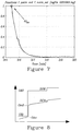
- An example of the f_norm curve is shown in figure 7 .
- the next step is to make a least mean square line fit to In(f_norm) in the range 0.2 ⁇ f_norm ⁇ 0.8, i.e. the initial part of the curve (different ranges might be used e.g. 0,1:0,9).
- the mean value of Cdi during the step is calculated. To get the most appropriate mean value we use data between (t0 Cdi + 3 minutes) and (tf Cdi - 1 minute). This excludes any overshoot effects and possible end effects and focuses on data being the base for the clearance and access flow estimations.
- the mean value is denoted Cdi step,mean .
- Cdo pre,mean a value representing the pre step Cdo parameter is needed.
- Cdo pre,mean a mean value of the data. It is denoted Cdo pre,mean .
- Cdo corr Cdo + (Cdo2 - Cdo pre,mean )* Cdi diff /step size.
- Another problem is that the correction is actually only valid when the needles are in the normal position. In the reverse position the clearance is lower and the correction should hence have been somewhat smaller. Since the difference between K n and K r is quite small and since we are discussing only the correction, which is small, we assume that the error we introduce is very small.
- the method further comprises a step of consisting in mathematical computation of the conductivity curve downstream from the filtration unit in order thereby to determine a characteristic time tStartCF beyond which the conductivity curve has stabilized after undergoing the effects of the imposed change in conductivity.
- Said characteristic time tStartCF is given by the sum of two terms, a first term t target which is function of the conductivity curve and a second term tcbf which is function of the blood flow.
- tA clr which is a time representative of the effects of the transient due the conductivity change in the upstream liquid. Indeed tA clr depends upon several factors among which we can mention the filter volume, blood and dyalisis liquid flows, the conductivity step and so on depending on which tA clr moves near or far from the terminal instant of the transient.
- Cdo corr data between t0 Cdo and tRev. The procedure is similar to what was described for finding tO Cdi but instead of trying to find a "baseline" towards which the area under Cdo corr should be created we instead use the function unit_f above.
- the area referred to is therefore the one restrained by unit_f and the t-axis.
- t tRev.
- tA clr is then defined as the point where the line crosses the t-axis, i.e. where the line has its zero value. Since the area function is nice, i.e. very little noise, one could (to get less calculations) instead of making a least mean square fit, use a line going through the endpoints of the interval.
- the next step is to construct a line going through the points (t0 Cdo , CdoO) and (tA clr , CdoA), see figure 2 .
- This line is extrapolated to a conductivity equal to Cdo pre + step size.
- the time point then obtained is called t target . Where, in time, this point is located, compared to t0 Cdo . is dependent on the shape of the curve, i.e. the dialyser used, blood flow, dialysis solution flow and also parameters origin from the patient. It expresses a sort of time constant for the curve.
- the time tcbf has two uses. The first is adding it to t target . By that, we will get to a position on the Cdo curve where most of the initial effects have decayed.
- the time point obtained (tstartCF) is the one from which we start using Cdo data for the subsequent estimation.
- the second use is for finding the best time for the clearance calculation (see below).
- Cdo_1n clr Cdi step,mean - sign*exp(c(1)*t+c(2)), where c(1) and c(2) are the coefficients from the fit.
- the function Cdo_1n clr will then give us the sought Cdo2 needed for the clearance calculation.
- Cdi2 is equal Cdi step,mean (alternatively also the set values Cdi set,step may be used) and Cdi1 is equal to Cdi pre,mean (alternatively also the set values Cdi set,pre may be used); it is also clear that, due to the symmetry of the clearance calculation expression, values of both Cdi2 and Cdi1, Cdo2 and Cdo1 may be inverted.
- Cdo1 is given by function Cdo pre , extended and taken at tCalc clr .
- Cdo pre is created by performing a line fit to Cdo data in the same interval as is used when assessing Cdo pre,mean .
- Qd and Quf are the flow rates of the dialysis solution and the UF respectively.
- a fixed time of 1.5 minutes is used for fitting a curve to Cdo-data in order to get Cdo2.
- the access flow is calculated from the step one get when shifting the blood flow to the needles, i.e. blood taken out upstream is shifted with blood entering downstream. This creates a recirculation in the fistula, which affects the efficiency of the dialysis. K e becomes less. How much the flow reversal reduces the efficiency is dependent on the access flow. The effect of the flow reversal is seen in the Cdo-curve as a small step ( Figure 9 ). The size of the step, along with the clearance gives the access flow.
- the method for calculating fistula flow generally comprises the step of determining the filter clearance as above described, when reversing the blood flow direction to the fistula and determining, by means of mathematical calculation, an outlet conductivity prior the reversal of the blood flow Cdon; furthermore the method includes the step of determining a conductivity of the outlet process fluid Cdor following the reversal in blood flow and setting or estimating an inlet conductivity Cdi after the imposition of a change in conductivity.
- t0 acc the point in time at which the conductivities for the access flow calculation, should be taken.
- t0 acc the point in time at which the conductivities for the access flow calculation
- the correct time lies some time after t0 acc .
- tA gcc is derived in the same way as was tA clr .
- unit_f acc In(sign * (Cdi step,mean - Cdo corr )/potential)).
- unit_f acc In(sign * (Cdi step,mean - Cdo corr )/potential)).
- unit_f acc In(sign * (Cdi step,mean - Cdo corr )/potential)).
- the area function The area referred to is the one restrained by unit_f acc and the t-axis.
- tA acc is then defined as the point where the line crosses the t-axis, i.e. where the line has its zero value.
- K e is the effective clearance obtained as above.
- Q uf is the UF.
- the conductivities are best described by figures 9 and 11 .
- Cdo_1n acc gives at the same time point Cdor.
- Cdi is given by Cdi step,mean .
- the invention achieves important advantages.
- the method for determining the conductivity carried out in the machine according to the present invention allows to increase the accuracy of calculation of clearance and of access flow.
- the method is adapted to be used with different blood treatment machines and gives good results for different patients in different conditions.
- the present method allows also to more accurately access a conductivity needed for calculation of the clearance and of access flow by giving better estimation of the time point when the transition effect starts and ends.
Landscapes
- Health & Medical Sciences (AREA)
- Heart & Thoracic Surgery (AREA)
- Urology & Nephrology (AREA)
- Anesthesiology (AREA)
- Vascular Medicine (AREA)
- Engineering & Computer Science (AREA)
- Emergency Medicine (AREA)
- Biomedical Technology (AREA)
- Hematology (AREA)
- Life Sciences & Earth Sciences (AREA)
- Animal Behavior & Ethology (AREA)
- General Health & Medical Sciences (AREA)
- Public Health (AREA)
- Veterinary Medicine (AREA)
- External Artificial Organs (AREA)
Claims (47)
- Blutbehandlungsmaschine umfassend:- mindestens eine Filtrationseinheit mit einem ersten Abteil zur Blutzirkulation und einem zweiten Abteil zur Zirkulation des Behandlungsfluids, wobei die ersten und zweiten Abteile durch Zwischenlegen mindestens einer semipermeablen Membran voneinander getrennt sind;- Mittel zum Ändern der Leitfähigkeit des Behandlungsfluids aufwärts von der Filtrationseinheit;- mindestens einen ersten und einen zweiten Sensor, die aufwärts und abwärts von der Filtrationseinheit installiert sind, zum Messen der Leitfähigkeit des Prozessfluids aufwärts bzw. abwärts von der Einheit;- eine Steuereinheit, die die Vorrichtungen regelt, um die Leitfähigkeit des Prozessfluids zu ändern, und die Leitfähigkeitssignale aus den vorgenannten ersten und zweiten Sensoren empfangen kann,wobei die Steuereinheit ein Verfahren zum Bestimmen der Leitfähigkeit eines Behandlungsfluids abwärts von der Filtrationseinheit durchführt, wobei das Verfahren die folgenden Schritte umfasst:- Erzeugen eines Flusses von Behandlungsfluid durch das zweite Abteil der Filtrationseinheit;- Auferlegen, für eine vorbestimmte Zeitspanne, einer Änderung der Leitfähigkeit des Behandlungsfluids am Eingang der Filtrationseinheit, um dadurch eine veranlasste Leitfähigkeitsänderung im Fluid am Ausgang der Filtrationseinheit zu verursachen;- Messen, über die Zeit, einer vorbestimmten Anzahl von Leitfähigkeitswerten Cdo abwärts von der Filtrationseinheit und einer Leitfähigkeitskurve des Behandlungsfluids abwärts von der Filtrationseinheit zugehörend, dadurch gekennzeichnet, dass das Verfahren weiter umfasst die Schritte von:- Definieren mindestens einer mathematischen Interpolationsfunktion zum Zwecke des Schätzens des Musters der Leitfähigkeitskurve Cdo abwärts von der Filtrationseinheit in einer Zeitspanne nach dem Auftreten der veranlassten Leitfähigkeitsänderung;- Bestimmen einer charakteristischen Messzeit tcalcclr; wobei die Bestimmung der charakteristischen Messzeit tcalcclr die folgenden Unterschritte umfasst:- Schätzen einer Zwischenzeit tAclr, die einen Übergangsvorgang aufgrund der veranlassten Leitfähigkeitsänderung im Fluid darstellt;- Korrigieren der Zwischenzeit tAclr durch die Ergänzung eines zweiten Zeitglieds tcbf, das eine Funktion des Blutflusses ist;- Berechnen des Wertes der mathematischen Interpolationsfunktion zur charakteristischen Messzeit tcalcclr, wobei der Wert den Leitfähigkeitswert Cdo2 des Prozessfluids abwärts von der Filtrationseinheit nach der veranlassten Leitfähigkeitsänderung darstellt.
- Maschine nach Anspruch 1, dadurch gekennzeichnet, dass die im Eingangsfluid auferlegte Leitfähigkeitsänderung eine bekannte Wertänderung ist, die über die Zeit konstant bleibt, wobei die Änderung insbesondere eine positive Leitfähigkeitsänderung ist, d.h. eine Leitfähigkeitszunahme.
- Maschine nach Anspruch 2, dadurch gekennzeichnet, dass die charakteristische Messzeit tcalcclr

wobei Qb = Blutfluss. - Maschine nach Anspruch 2, dadurch gekennzeichnet, dass die Zwischenzeit tAclr unter Verwendung der Funktion unit_f berechnet wird:

wobei Cdistep,set = Wert der bekannten Leitfähigkeitsänderung am Eingang der Filtrationseinheit;
wobei Cdo = Leitfähigkeitswerte, die abwärts von der Filtrationseinheit gemessen werden;
wobei Cdistep,mean = Eingangsleitfähigkeitswert nach der Leitfähigkeitsänderung
wobei Cdopre,mean = durchschnittlicher Ausgangsleitfähigkeitswert vor der Leitfähigkeitsänderung,
und durch Ausführung einer Interpolation mit Schätzung nach kleinsten Quadraten auf den Daten des Bereichs, der zwischen die Funktion und die Zeitachse der x-Koordinate in eine vorbestimmte Zeitspanne fällt, wobei die Zwischenzeit tAclr mit dem Punkt zusammenfällt, an dem die Interpolationsfunktion die Zeitachse durchschneidet, d.h. einen Wert von Null annimmt,. - Maschine nach Anspruch 4, dadurch gekennzeichnet, dass die vorbestimmte Zeitspanne für die Schätzung nach kleinsten Quadraten der Funktion unit_f zwischen (tRev - 1,5 min) und tRev liegt,
wobei tRev ein Punkt der Umkehr der Blutleitungen ist. - Maschine nach Anspruch 1, dadurch gekennzeichnet, dass sie auch die folgenden Schritte umfasst:- Messen, über die Zeit, einer vorbestimmten Anzahl von Leitfähigkeitswerten des Behandlungsfluids aufwärts von der Filtrationseinheit und einer Leitfähigkeitskurve des Behandlungsfluids aufwärts von der Filtrationseinheit zugehörend;- Bestimmen einer charakteristischen Zeit t0Cdo der Leitfähigkeitskurve des Behandlungsfluids abwärts von der Filtrationseinheit, wobei die charakteristische Zeit t0Cdo dem Startpunkt der Leitfähigkeitskurve des Behandlungsfluids abwärts von der Filtrationseinheit entspricht;- Bestimmen einer charakteristischen Zeit tOCdi der Leitfähigkeitskurve des Behandlungsfluids aufwärts von der Filtrationseinheit, wobei die charakteristische Zeit t0Cdi dem Startpunkt der Leitfähigkeitskurve des Behandlungsfluids aufwärts von der Filtrationseinheit entspricht;- Synchronisieren der Leitfähigkeitskurven auf Basis der charakteristischen Zeiten t0Cdo und t0Cdi, die von der Kurven aufwärts und abwärts von der Filtrationseinheit bestimmt sind, um den Vergleich der jeweiligen Leitfähigkeitswerte zu ermöglichen, wobei die Synchronisation durch Bewegen einer der Leitfähigkeitskurven zum Startpunkt der anderen Kurve ausgeführt wird;- Vergleichen der Leitfähigkeitskurven aufwärts und abwärts von der Filtrationseinheit, nachdem sie synchronisiert worden sind, um dadurch einen oder mehrere abwärtsliegende Leitfähigkeitswerte zu bestimmen.
- Maschine nach Anspruch 6, dadurch gekennzeichnet, dass die charakteristische Zeit tOCdi der aufwärtsliegenden Leitfähigkeitskurve mit dem Punkt, an dem die Leitfähigkeitsänderung in der Leitfähigkeitskurve aufwärts von der Filtrationseinheit auftritt, zusammenfällt, wobei die charakteristische Zeit t0Cdo der abwärtsliegenden Leitfähigkeitskurve dem Punkt, an dem die veranlasste Leitfähigkeitsänderung abwärts von der Filtrationseinheit auftritt, entspricht.
- Maschine nach Anspruch 7, dadurch gekennzeichnet, dass die charakteristische Zeit tOCdi der aufwärtsliegenden Leitfähigkeitskurve durch Schätzung eines Bereichs, der unter der Eingangsleitfähigkeitskurve definiert ist, berechnet wird, wobei die charakteristische Zeit t0Cdi mit dem Punkt, an dem der Bereich unter der Kurve einen größeren durchschnittlichen Wert als eine vorbestimmte Schwelle annimmt, zusammenfällt.
- Maschine nach Anspruch 7, dadurch gekennzeichnet, dass die Bestimmung der charakteristischen Zeit t0Cdo der Leitfähigkeitskurve abwärts von der Filtrationseinheit einen Schritt bestehend aus einer vorläufigen Schätzung des Wertes der charakteristischen Zeit umfasst und danach die vorläufige Schätzung korrigiert wird.
- Maschine nach Anspruch 9, dadurch gekennzeichnet, dass die vorläufige Schätzung des Wertes der charakteristischen Zeit der Leitfähigkeitskurve abwärts von der Filtrationseinheit die folgenden Unterschritte umfasst:- Bestimmen der durchschnittlichen Leitfähigkeit am Ausgang der Filtrationseinheit Cdopre,mean vor den Auswirkungen der Leitfähigkeitsänderung, wobei die Bestimmung auf Basis eines Mittelwertes, z.B. eines arithmetischen Mittels, der gemessenen Leitfähigkeitswerte Cdo vor den Änderungsauswirkungen ausgeführt wird;- Vergleichen der gemessenen Leitfähigkeitswerte am Ausgang der Filtrationseinheit Cdo mit dem vorher bestimmten durchschnittlichen Ausgangsleitfähigkeitswert Cdopre,mean;- Schätzen des Punkts, an dem die gemessenen Leitfähigkeitswerte Cdo stetig größer zu sein scheinen als der vorher bestimmte durchschnittliche Ausgangsleitfähigkeitswert Cdopre,mean.
- Maschine nach Anspruch 10, dadurch gekennzeichnet, dass, wenn die gemessenen Leitfähigkeitswerte Cdo den durchschnittlichen Ausgangsleitfähigkeitswert Cdopre,mean mehrfach übersteigen, die vorläufige Schätzung der charakteristischen Zeit t0Cdo der Leitfähigkeitskurve abwärts von der Filtrationseinheit mit dem Punkt der letzten Bedingung zusammenfällt, in der die gemessenen Leitfähigkeitswerte Cdo größer sind, als der durchschnittliche Ausgangsleitfähigkeitswert Cdopre,mean.
- Maschine nach Anspruch 9, dadurch gekennzeichnet, dass der Schritt des Korrigierens der vorläufigen Schätzung des Wertes der charakteristischen Zeit t0Cdo der Leitfähigkeitskurve abwärts von der Filtrationseinheit die folgenden Unterschritte umfasst:- Erstellen eines geeigneten mathematischen Ausdrucks unit_f, der eine Funktion der abwärts von der Filtrationseinheit Cdo gemessenen Leitfähigkeitswerte und der bekannten Leitfähigkeitsänderung des Eingangsfluids, Cdistep,set, ist, wobei der Ausdruck, falls notwendig, normalisiert ist;- Ausführen einer Schätzung nach kleinsten Quadraten des Ausdrucks unit_f in einer vorbestimmten Zeitspanne.
- Maschine nach Anspruch 12, dadurch gekennzeichnet, dass der verwendete mathematische Ausdruck wie folgt ist:

wobei Cdistep,set = Wert der bekannten Leitfähigkeitsänderung am Eingang der Filtrationseinheit;
wobei Cdo = Leitfähigkeitswerte, die abwärts von der Filtrationseinheit gemessen werden
wobei Cdistep,mean = Eingangsleitfähigkeitswert nach der Leitfähigkeitsänderung;
wobei Cdopre,mean = durchschnittlicher Ausgangsleitfähigkeitswert vor der Leitfähigkeitsänderung. - Maschine nach Anspruch 13, dadurch gekennzeichnet, dass die Schätzung nach kleinsten Quadraten auf dem mathematischen Ausdruck unit_f ausgeführt wird, und die Schätzung ist wie folgt

- Maschine nach Anspruch 12, dadurch gekennzeichnet, dass der Schritt des Korrigierens der vorläufigen Schätzung des Wertes der charakteristischen Zeit der Leitfähigkeitskurve abwärts von der Filtrationseinheit die zusätzlichen Unterschritte umfasst, von:- Erstellen einer mathematischen Funktion f_norm, die eine Funktion der Koeffizienten cclr (1) und cclr (2) aus der vorherigen Interpolation nach kleinsten Quadraten, eine Funktion der bekannten Leitfähigkeitsänderung Cdistep,set des Eingangsfluids und eine Funktion der Leitfähigkeitswerte abwärts von der Filtrationseinheit Cdo ist, wobei die mathematische Funktion f_norm, falls notwendig, normalisiert ist,- Ausführen einer Interpolation nach kleinsten Quadraten auf der mathematischen Funktion f_norm in einem vorbestimmten Wertbereich.
- Maschine nach den Ansprüchen 14 und 15, dadurch gekennzeichnet, dass die verwendete mathematische Funktion wie folgt ist:

- Maschine nach Anspruch 15, dadurch gekennzeichnet, dass sie einen weiteren Unterschritt bestehend aus der Erstellung einer mathematischen Schätzfunktion f_norm_est umfasst, die eine Funktion der Koeffizienten cclr (3) und cclr (4) aus der Interpolation nach kleinsten Quadraten der mathematischen Funktion ist.
- Maschine nach Anspruch 16, dadurch gekennzeichnet, dass die vorbestimmte Zeitspanne der mathematischen Funktion f_norm, in der die Interpolation auszuführen ist, zwischen 0,1 und 0,9, insbesondere zwischen 0,2 und 0,8, liegt.
- Maschine nach Anspruch 17, dadurch gekennzeichnet, dass der korrigierte Wert t0Cdo der charakteristischen Zeit der Leitfähigkeitskurve abwärts von der Filtrationseinheit mit dem Punkt, an dem die mathematische Schätzfunktion f_norm_est einen Wert von eins annimmt, zusammenfällt.
- Maschine nach Anspruch 17, dadurch gekennzeichnet, dass die verwendete mathematische Schätzfunktion wie folgt ist:

wobei cclr (3) und cclr (4) die Koeffizienten aus der Interpolation nach kleinsten Quadraten des natürliches Logarithmus der mathematischen Funktion f_norm sind. - Maschine nach Anspruch 20, dadurch gekennzeichnet, dass der korrigierte Wert der charakteristischen Zeit t0Cdo erhalten wird unter Verwendung der folgenden Formel:

- Maschine nach Anspruch 12, dadurch gekennzeichnet, dass die vorbestimmte Zeitspanne des mathematischen Ausdrucks unit_f, in der die Interpolation auszuführen ist, wesentlich zwischen einem Punkt der Umkehr der Blutleitung tRev - 1,5 Minuten und dem Punkt der Umkehr der Blutleitung tRev liegt.
- Maschine nach Anspruch 6, dadurch gekennzeichnet, dass der Schritt des Synchronisierens der Leitfähigkeitskurven eine relative Verschiebung zwischen den beiden beinhaltet, der ein Wert D zugeschrieben wird, der eine Funktion der charakteristischen Zeiten t0Cdi und t0Cdo ist, die von den Kurven aufwärts und abwärts von der Filtrationseinheit bestimmt sind.
- Maschine nach einem der vorhergehenden Ansprüche, dadurch gekennzeichnet, dass sie einen Schritt des Bestimmens der durchschnittlichen Eingangsleitfähigkeit nach der auferlegten Leitfähigkeitsänderung Cdistep,mean umfasst, wobei die Bestimmung sich auf einen Mittelwert, z.B. ein arithmetisches Mittel, der gemessenen Leitfähigkeitswerte Cdi nach den Änderungsauswirkungen beruht.
- Maschine nach Anspruch 24, dadurch gekennzeichnet, dass die zur Bestimmung der durchschnittlichen Eingangsleitfähigkeit nach der Leitfähigkeitsänderung Cdistep,mean verwendeten Leitfähigkeitswerte Cdi wieder in die Zeitspanne zwischen dem Punkt, an dem die Leitfähigkeitsänderung in der Leitfähigkeitskurve aufwärts von der Filtrationseinheit auftritt, tOCdi + 3 Minuten, und dem Punkt, an dem die Auswirkungen der Leitfähigkeitsänderung in derselben Kurve beendet sind, tfCdi - 1 Minute, fällt.
- Maschine nach einem der vorhergehenden Ansprüche, dadurch gekennzeichnet, dass ein Punkt tfCdi, an dem die Auswirkungen der Leitfähigkeitsänderung in der Leitfähigkeitskurve aufwärts von der Filtrationseinheit beendet sind, durch Schätzung eines Bereichs unter der auferlegten Leitfähigkeitskurve berechnet wird, wobei der Punkt tfCdi durch den Punkt, an dem der Bereich unter der Kurve einen durchschnittlichen Wert unter einer vorbestimmten Schwelle annimmt, definiert ist.
- Maschine nach einem der vorhergehenden Ansprüche, dadurch gekennzeichnet, dass die aufwärts von der Filtrationseinheit gemessenen Leitfähigkeitswerte Cdi gefiltert werden, um die langfristigen Schwankungen zwischen den Werten zu beseitigen.
- Maschine nach Anspruch 27, dadurch gekennzeichnet, dass nur die in einer signifikanten Zeitspanne gemessenen Eingangsleitfähigkeitswerte Cdi gefiltert werden, z.B. in der Zeitspanne zwischen dem Punkt, an dem die Leitfähigkeitsänderung in der Leitfähigkeitskurve aufwärts von der Filtrationseinheit auftritt, t0Cdi + 0,5 Minuten, und dem Punkt, an dem die Auswirkungen der Leitfähigkeitsänderung in derselben Kurve beendet sind, tfCdi - 0,5 Minuten.
- Maschine nach Anspruch 27, dadurch gekennzeichnet, dass der verwendete mathematische Filter exponentiellen Typs ist.
- Maschine nach Anspruch 29, dadurch gekennzeichnet, dass nach der Filtration die Leitfähigkeitskurve aufwärts von der Filtrationseinheit Cdi den folgenden Ausdruck erfüllt:

- Maschine nach Anspruch 30, dadurch gekennzeichnet, dass der verwendete Filtrationsfaktor N Werte zwischen 150 und 250, insbesondere von 200, annimmt, wobei die für die Cdi-Daten verwendete Abtastfrequenz 0,01 bis 0,1 min, insbesondere 0,033 beträgt.
- Maschine nach einem der vorhergehenden Ansprüche, dadurch gekennzeichnet, dass die gemessenen Werte der Leitfähigkeitskurve abwärts von der Filtrationseinheit Cdo auf der Basis der Leitfähigkeitsschwankungen, die in den gemessenen Werten der Leitfähigkeitskurve aufwärts von der Filtrationseinheit Cdi erzeugt werden, korrigiert werden.
- Maschine nach den Ansprüchen 27 und 32, dadurch gekennzeichnet, dass die gemessenen Werte der abwärtsliegenden Leitfähigkeitskurve Cdo auf der Basis der vorher gemessenen, gefilterten Werte Cdifilt korrigiert werden.
- Maschine nach den Ansprüchen 30 und 32, dadurch gekennzeichnet, dass die korrigierte Leitfähigkeitskurve abwärts von der Filtrationseinheit den folgenden Ausdruck erfüllt:

Inkrementgröße = Cdipre,mean - Cdistep,mean
Cdo2 = Leitfähigkeitswert abwärts von der Filtrationseinheit nach den Auswirkungen der Leitfähigkeitsänderung. - Maschine nach den Ansprüchen 14 und 34, dadurch gekennzeichnet, dass zum Berechnen von Cdocorr ein vorläufiger Schätzwert von Cdo2 verwendet wird, wobei die Schätzung durch den Wert, den die Funktion Cdo_Inclr am Punkt t=t0Cdo annimmt, definiert ist.
- Maschine nach Anspruch 1, dadurch gekennzeichnet, dass sie einen Schritt weiter umfasst, der aus der mathematischen Berechnung der Leitfähigkeitskurve Cdo abwärts von der Filtrationseinheit besteht, um dadurch eine charakteristische Zeit tStartCF zu bestimmen, über der die Leitfähigkeitskurve sich stabilisiert hat, nachdem sie den Auswirkungen der auferlegten Leitfähigkeitsänderung unterzogen wurde.
- Maschine nach Anspruch 36, dadurch gekennzeichnet, dass die charakteristische Zeit tStartCF durch die Summe zwei Glieder erhalten wird, eines ersten Glieds ttarget, das eine Funktion der Leitfähigkeitskurve ist, und eines zweiten Glieds tcbf, die eine Funktion des Blutflusses ist.
- Maschine nach Anspruch 37, dadurch gekennzeichnet, dass das zweite Glied tcbf die folgende Relation erfüllt:

- Maschine nach den Ansprüchen 6 und 37, dadurch gekennzeichnet, dass die Bestimmung des ersten Glieds ttarget zum Berechnen der charakteristischen Zeit die Schritte beinhaltet, von:- Schätzen einer Zwischenzeit tAclr,- Ableiten des ersten Glieds ttarget, wobei das erste Glied ttarget mit der Zeit, die eine gerade Linie durch die Punkte (t0Cdo; CdoO) und C(tAclr; Cd0A) bildet, zusammenfällt und den Wert Cdopre,mean + Inkrementgröße annimmtwobei Cdo0 und CdoA die von der Kurve Cdo bei den Punkten t0Cdo und tAclr angenommenen Werte sind, wobei Cdop-re,mean = die durchschnittliche Ausgangsleitfähigkeit vor den Auswirkungen der Leitfähigkeitsänderung ist.
- Maschine nach Anspruch 39, dadurch gekennzeichnet, dass die Zwischenzeit tAclr berechnet wird unter Verwendung der folgenden Funktion:

- Maschine nach Anspruch 40, dadurch gekennzeichnet, dass die vorbestimmte Zeitspanne für die Schätzung nach kleinsten Quadraten der Funktion unit_f zwischen (tRev - 1,5 min) und tRev liegt.
- Maschine nach Anspruch 1, dadurch gekennzeichnet, dass sie weiter einen Schritt des Berechnens der Leitfähigkeit am Ausgang der Filtrationseinheit nach der auferlegten Leitfähigkeitsänderung umfasst.
- Maschine nach Anspruch 42, dadurch gekennzeichnet, dass der Schritt des Berechnens der Leitfähigkeit am Ausgang der Filtrationseinheit einen Unterschritt beinhaltet, der aus der Interpolation nach kleinsten Quadraten einer mathematischen Kurve f besteht, die eine Funktion von Cdistep,mean und Cdocorr in einer bestimmten Zeitspanne ist.
- Maschine nach Anspruch 43, dadurch gekennzeichnet, dass die mathematische Kurve die folgende Form annimmt:

- Maschine nach Anspruch 43, dadurch gekennzeichnet, dass die vorbestimmte Zeitspanne zwischen tstartCFclr und tstartCFclr +1,5 min liegt.
- Maschine nach Anspruch 43, dadurch gekennzeichnet, dass der Schritt des Berechnens der Leitfähigkeit am Ausgang der Filtrationseinheit den Unterschritt des Erstellens einer Gleichung Cdo_1nclr weiter umfasst, die eine Funktion von Cdiset,mean und c(1) und c(2), wobei c(1) und c(2) = Koeffizienten aus der Interpolation nach kleinsten Quadraten der Funktion f sind.
- Maschine nach Anspruch 46, dadurch gekennzeichnet, dass die Gleichung die folgende Form zeigt:

Applications Claiming Priority (2)
| Application Number | Priority Date | Filing Date | Title |
|---|---|---|---|
| US57812004P | 2004-06-08 | 2004-06-08 | |
| US578120P | 2004-06-08 |
Publications (3)
| Publication Number | Publication Date |
|---|---|
| EP1604698A2 EP1604698A2 (de) | 2005-12-14 |
| EP1604698A3 EP1604698A3 (de) | 2011-07-20 |
| EP1604698B1 true EP1604698B1 (de) | 2018-09-12 |
Family
ID=34981180
Family Applications (1)
| Application Number | Title | Priority Date | Filing Date |
|---|---|---|---|
| EP05011504.7A Expired - Lifetime EP1604698B1 (de) | 2004-06-08 | 2005-05-27 | Methode für Berechnungen auf der Basis der Leitfähigkeit einer Behandlungsflüssigkeit in einem Gerät zur Behandlung von Blut |
Country Status (1)
| Country | Link |
|---|---|
| EP (1) | EP1604698B1 (de) |
Families Citing this family (1)
| Publication number | Priority date | Publication date | Assignee | Title |
|---|---|---|---|---|
| DE102013103220A1 (de) | 2013-03-28 | 2014-10-02 | B. Braun Avitum Ag | Verfahren und Vorrichtung zur Bestimmung eines Rezirkulationszustands |
Family Cites Families (4)
| Publication number | Priority date | Publication date | Assignee | Title |
|---|---|---|---|---|
| SE465404B (sv) | 1988-03-03 | 1991-09-09 | Gambro Ab | Dialyssystem |
| FR2713937B1 (fr) | 1993-12-17 | 1996-05-31 | Hospal Ind | Procédé de détermination d'un paramètre significatif du progrès d'un traitement extracorporel de sang. |
| US6691040B2 (en) * | 1999-12-02 | 2004-02-10 | Hospal Ag | Method for determining a parameter indicative of the progress of an extracorporeal blood treatment |
| SE0200370D0 (sv) * | 2002-02-08 | 2002-02-08 | Gambro Lundia Ab | Method and apparatus for determining access flow |
-
2005
- 2005-05-27 EP EP05011504.7A patent/EP1604698B1/de not_active Expired - Lifetime
Non-Patent Citations (1)
| Title |
|---|
| None * |
Also Published As
| Publication number | Publication date |
|---|---|
| EP1604698A2 (de) | 2005-12-14 |
| EP1604698A3 (de) | 2011-07-20 |
Similar Documents
| Publication | Publication Date | Title |
|---|---|---|
| US7815809B2 (en) | Method for conductivity calculation in a treatment fluid upstream and downstream a filtration unit in apparatuses for the blood treatment | |
| JP6362267B2 (ja) | 体外血液処理の動作状態を検出するためのデバイス及び方法 | |
| KR102220982B1 (ko) | 체외 혈액 치료 중 재순환을 검출하는 장치 및 방법 | |
| EP1938847B1 (de) | Vorrichtung zur Bestimmung des Blutzugangsflusses | |
| AU2013365795B2 (en) | An apparatus for extracorporeal blood treatment. | |
| JP2002514120A (ja) | 透析の効率を計算する方法および装置 | |
| JP2000000300A (ja) | 血液処理装置のための安全装置および血液処理装置の安全性を高めるための方法 | |
| JP2002533170A (ja) | 体外血液処理中に血液成分の分布量を算定するための方法およびこの方法を実施するための装置 | |
| JP2017523885A (ja) | 透析患者の血液の透析前特性を判定する機能を有する透析装置 | |
| JP2012504481A (ja) | 体外での血液処理のための装置及び前記装置を管理する方法 | |
| CN113631205B (zh) | 借助扩散平衡的再循环测量 | |
| JP6991155B2 (ja) | 血液処理機器iiの接続テスト | |
| US20240267473A1 (en) | Measuring access flow rate by use of blood treatment machine | |
| CN108472429B (zh) | 具有用于识别分流再循环的机构的透析仪 | |
| EP1604698B1 (de) | Methode für Berechnungen auf der Basis der Leitfähigkeit einer Behandlungsflüssigkeit in einem Gerät zur Behandlung von Blut | |
| CN114082020A (zh) | 一种血液透析用自动化枸橼酸抗凝设备及其控制系统 | |
| Di Filippo et al. | Optimization of sodium removal in paired filtration dialysis by single pool sodium and conductivity kinetic models | |
| CN102026676A (zh) | 血液透析装置 | |
| WO2020074733A1 (en) | Extracorporeal blood treatment apparatus and method for monitoring pressures in an extracorporeal blood treatment apparatus | |
| JPWO2011074603A1 (ja) | 血液透析装置 | |
| EP3870035B1 (de) | System, computersystem und computerprogramm zur bestimmung eines kardiovaskulären parameters | |
| WO2018001994A1 (en) | Connection test for blood treatment machines i | |
| EP4098291B1 (de) | Vorrichtung zur extrakorporalen blutbehandlung | |
| Locatelli et al. | Ionic Dialysance and Conductivity Modeling | |
| JP2024517095A (ja) | 二次膜を除去するための体外デバイスおよび方法 |
Legal Events
| Date | Code | Title | Description |
|---|---|---|---|
| PUAI | Public reference made under article 153(3) epc to a published international application that has entered the european phase |
Free format text: ORIGINAL CODE: 0009012 |
|
| AK | Designated contracting states |
Kind code of ref document: A2 Designated state(s): AT BE BG CH CY CZ DE DK EE ES FI FR GB GR HU IE IS IT LI LT LU MC NL PL PT RO SE SI SK TR |
|
| AX | Request for extension of the european patent |
Extension state: AL BA HR LV MK YU |
|
| 111Z | Information provided on other rights and legal means of execution |
Free format text: AT BE BG CH CY CZ DE DK EE ES FI FR GB GR HU IE IS IT LT LU MC NL PL PT RO SE SI SK TR Effective date: 20090504 |
|
| PUAL | Search report despatched |
Free format text: ORIGINAL CODE: 0009013 |
|
| AK | Designated contracting states |
Kind code of ref document: A3 Designated state(s): AT BE BG CH CY CZ DE DK EE ES FI FR GB GR HU IE IS IT LI LT LU MC NL PL PT RO SE SI SK TR |
|
| AX | Request for extension of the european patent |
Extension state: AL BA HR LV MK YU |
|
| 17P | Request for examination filed |
Effective date: 20110831 |
|
| AKX | Designation fees paid |
Designated state(s): AT BE BG CH CY CZ DE DK EE ES FI FR GB GR HU IE IS IT LI LT LU MC NL PL PT RO SE SI SK TR |
|
| D11X | Information provided on other rights and legal means of execution (deleted) | ||
| 17Q | First examination report despatched |
Effective date: 20130110 |
|
| GRAP | Despatch of communication of intention to grant a patent |
Free format text: ORIGINAL CODE: EPIDOSNIGR1 |
|
| STAA | Information on the status of an ep patent application or granted ep patent |
Free format text: STATUS: GRANT OF PATENT IS INTENDED |
|
| RAP1 | Party data changed (applicant data changed or rights of an application transferred) |
Owner name: GAMBRO LUNDIA AB |
|
| RIN1 | Information on inventor provided before grant (corrected) |
Inventor name: JANSSON, OLOF Inventor name: STERNBY, JAN PETER Inventor name: PERSSON, ROLAND |
|
| INTG | Intention to grant announced |
Effective date: 20180502 |
|
| GRAS | Grant fee paid |
Free format text: ORIGINAL CODE: EPIDOSNIGR3 |
|
| GRAA | (expected) grant |
Free format text: ORIGINAL CODE: 0009210 |
|
| STAA | Information on the status of an ep patent application or granted ep patent |
Free format text: STATUS: THE PATENT HAS BEEN GRANTED |
|
| AK | Designated contracting states |
Kind code of ref document: B1 Designated state(s): AT BE BG CH CY CZ DE DK EE ES FI FR GB GR HU IE IS IT LI LT LU MC NL PL PT RO SE SI SK TR |
|
| REG | Reference to a national code |
Ref country code: GB Ref legal event code: FG4D |
|
| REG | Reference to a national code |
Ref country code: CH Ref legal event code: EP |
|
| REG | Reference to a national code |
Ref country code: IE Ref legal event code: FG4D |
|
| REG | Reference to a national code |
Ref country code: DE Ref legal event code: R096 Ref document number: 602005054586 Country of ref document: DE |
|
| REG | Reference to a national code |
Ref country code: AT Ref legal event code: REF Ref document number: 1039812 Country of ref document: AT Kind code of ref document: T Effective date: 20181015 |
|
| REG | Reference to a national code |
Ref country code: NL Ref legal event code: MP Effective date: 20180912 |
|
| REG | Reference to a national code |
Ref country code: LT Ref legal event code: MG4D |
|
| PG25 | Lapsed in a contracting state [announced via postgrant information from national office to epo] |
Ref country code: LT Free format text: LAPSE BECAUSE OF FAILURE TO SUBMIT A TRANSLATION OF THE DESCRIPTION OR TO PAY THE FEE WITHIN THE PRESCRIBED TIME-LIMIT Effective date: 20180912 Ref country code: FI Free format text: LAPSE BECAUSE OF FAILURE TO SUBMIT A TRANSLATION OF THE DESCRIPTION OR TO PAY THE FEE WITHIN THE PRESCRIBED TIME-LIMIT Effective date: 20180912 Ref country code: BG Free format text: LAPSE BECAUSE OF FAILURE TO SUBMIT A TRANSLATION OF THE DESCRIPTION OR TO PAY THE FEE WITHIN THE PRESCRIBED TIME-LIMIT Effective date: 20181212 Ref country code: GR Free format text: LAPSE BECAUSE OF FAILURE TO SUBMIT A TRANSLATION OF THE DESCRIPTION OR TO PAY THE FEE WITHIN THE PRESCRIBED TIME-LIMIT Effective date: 20181213 Ref country code: SE Free format text: LAPSE BECAUSE OF FAILURE TO SUBMIT A TRANSLATION OF THE DESCRIPTION OR TO PAY THE FEE WITHIN THE PRESCRIBED TIME-LIMIT Effective date: 20180912 |
|
| PG25 | Lapsed in a contracting state [announced via postgrant information from national office to epo] |
Ref country code: ES Free format text: LAPSE BECAUSE OF FAILURE TO SUBMIT A TRANSLATION OF THE DESCRIPTION OR TO PAY THE FEE WITHIN THE PRESCRIBED TIME-LIMIT Effective date: 20180912 |
|
| REG | Reference to a national code |
Ref country code: AT Ref legal event code: MK05 Ref document number: 1039812 Country of ref document: AT Kind code of ref document: T Effective date: 20180912 |
|
| PG25 | Lapsed in a contracting state [announced via postgrant information from national office to epo] |
Ref country code: CZ Free format text: LAPSE BECAUSE OF FAILURE TO SUBMIT A TRANSLATION OF THE DESCRIPTION OR TO PAY THE FEE WITHIN THE PRESCRIBED TIME-LIMIT Effective date: 20180912 Ref country code: IT Free format text: LAPSE BECAUSE OF FAILURE TO SUBMIT A TRANSLATION OF THE DESCRIPTION OR TO PAY THE FEE WITHIN THE PRESCRIBED TIME-LIMIT Effective date: 20180912 Ref country code: AT Free format text: LAPSE BECAUSE OF FAILURE TO SUBMIT A TRANSLATION OF THE DESCRIPTION OR TO PAY THE FEE WITHIN THE PRESCRIBED TIME-LIMIT Effective date: 20180912 Ref country code: IS Free format text: LAPSE BECAUSE OF FAILURE TO SUBMIT A TRANSLATION OF THE DESCRIPTION OR TO PAY THE FEE WITHIN THE PRESCRIBED TIME-LIMIT Effective date: 20190112 Ref country code: EE Free format text: LAPSE BECAUSE OF FAILURE TO SUBMIT A TRANSLATION OF THE DESCRIPTION OR TO PAY THE FEE WITHIN THE PRESCRIBED TIME-LIMIT Effective date: 20180912 Ref country code: PL Free format text: LAPSE BECAUSE OF FAILURE TO SUBMIT A TRANSLATION OF THE DESCRIPTION OR TO PAY THE FEE WITHIN THE PRESCRIBED TIME-LIMIT Effective date: 20180912 Ref country code: NL Free format text: LAPSE BECAUSE OF FAILURE TO SUBMIT A TRANSLATION OF THE DESCRIPTION OR TO PAY THE FEE WITHIN THE PRESCRIBED TIME-LIMIT Effective date: 20180912 Ref country code: RO Free format text: LAPSE BECAUSE OF FAILURE TO SUBMIT A TRANSLATION OF THE DESCRIPTION OR TO PAY THE FEE WITHIN THE PRESCRIBED TIME-LIMIT Effective date: 20180912 |
|
| PG25 | Lapsed in a contracting state [announced via postgrant information from national office to epo] |
Ref country code: PT Free format text: LAPSE BECAUSE OF FAILURE TO SUBMIT A TRANSLATION OF THE DESCRIPTION OR TO PAY THE FEE WITHIN THE PRESCRIBED TIME-LIMIT Effective date: 20190112 Ref country code: SK Free format text: LAPSE BECAUSE OF FAILURE TO SUBMIT A TRANSLATION OF THE DESCRIPTION OR TO PAY THE FEE WITHIN THE PRESCRIBED TIME-LIMIT Effective date: 20180912 |
|
| REG | Reference to a national code |
Ref country code: DE Ref legal event code: R097 Ref document number: 602005054586 Country of ref document: DE |
|
| PLBE | No opposition filed within time limit |
Free format text: ORIGINAL CODE: 0009261 |
|
| STAA | Information on the status of an ep patent application or granted ep patent |
Free format text: STATUS: NO OPPOSITION FILED WITHIN TIME LIMIT |
|
| PG25 | Lapsed in a contracting state [announced via postgrant information from national office to epo] |
Ref country code: DK Free format text: LAPSE BECAUSE OF FAILURE TO SUBMIT A TRANSLATION OF THE DESCRIPTION OR TO PAY THE FEE WITHIN THE PRESCRIBED TIME-LIMIT Effective date: 20180912 |
|
| 26N | No opposition filed |
Effective date: 20190613 |
|
| PG25 | Lapsed in a contracting state [announced via postgrant information from national office to epo] |
Ref country code: SI Free format text: LAPSE BECAUSE OF FAILURE TO SUBMIT A TRANSLATION OF THE DESCRIPTION OR TO PAY THE FEE WITHIN THE PRESCRIBED TIME-LIMIT Effective date: 20180912 |
|
| REG | Reference to a national code |
Ref country code: CH Ref legal event code: PL |
|
| PG25 | Lapsed in a contracting state [announced via postgrant information from national office to epo] |
Ref country code: LI Free format text: LAPSE BECAUSE OF NON-PAYMENT OF DUE FEES Effective date: 20190531 Ref country code: MC Free format text: LAPSE BECAUSE OF FAILURE TO SUBMIT A TRANSLATION OF THE DESCRIPTION OR TO PAY THE FEE WITHIN THE PRESCRIBED TIME-LIMIT Effective date: 20180912 Ref country code: CH Free format text: LAPSE BECAUSE OF NON-PAYMENT OF DUE FEES Effective date: 20190531 |
|
| REG | Reference to a national code |
Ref country code: BE Ref legal event code: MM Effective date: 20190531 |
|
| PG25 | Lapsed in a contracting state [announced via postgrant information from national office to epo] |
Ref country code: LU Free format text: LAPSE BECAUSE OF NON-PAYMENT OF DUE FEES Effective date: 20190527 |
|
| PG25 | Lapsed in a contracting state [announced via postgrant information from national office to epo] |
Ref country code: TR Free format text: LAPSE BECAUSE OF FAILURE TO SUBMIT A TRANSLATION OF THE DESCRIPTION OR TO PAY THE FEE WITHIN THE PRESCRIBED TIME-LIMIT Effective date: 20180912 |
|
| PG25 | Lapsed in a contracting state [announced via postgrant information from national office to epo] |
Ref country code: IE Free format text: LAPSE BECAUSE OF NON-PAYMENT OF DUE FEES Effective date: 20190527 |
|
| PG25 | Lapsed in a contracting state [announced via postgrant information from national office to epo] |
Ref country code: BE Free format text: LAPSE BECAUSE OF NON-PAYMENT OF DUE FEES Effective date: 20190531 |
|
| PG25 | Lapsed in a contracting state [announced via postgrant information from national office to epo] |
Ref country code: FR Free format text: LAPSE BECAUSE OF NON-PAYMENT OF DUE FEES Effective date: 20190531 |
|
| PG25 | Lapsed in a contracting state [announced via postgrant information from national office to epo] |
Ref country code: CY Free format text: LAPSE BECAUSE OF FAILURE TO SUBMIT A TRANSLATION OF THE DESCRIPTION OR TO PAY THE FEE WITHIN THE PRESCRIBED TIME-LIMIT Effective date: 20180912 |
|
| PG25 | Lapsed in a contracting state [announced via postgrant information from national office to epo] |
Ref country code: HU Free format text: LAPSE BECAUSE OF FAILURE TO SUBMIT A TRANSLATION OF THE DESCRIPTION OR TO PAY THE FEE WITHIN THE PRESCRIBED TIME-LIMIT; INVALID AB INITIO Effective date: 20050527 |
|
| PGFP | Annual fee paid to national office [announced via postgrant information from national office to epo] |
Ref country code: GB Payment date: 20220406 Year of fee payment: 18 Ref country code: DE Payment date: 20220406 Year of fee payment: 18 |
|
| REG | Reference to a national code |
Ref country code: DE Ref legal event code: R119 Ref document number: 602005054586 Country of ref document: DE |
|
| GBPC | Gb: european patent ceased through non-payment of renewal fee |
Effective date: 20230527 |
|
| PG25 | Lapsed in a contracting state [announced via postgrant information from national office to epo] |
Ref country code: DE Free format text: LAPSE BECAUSE OF NON-PAYMENT OF DUE FEES Effective date: 20231201 Ref country code: GB Free format text: LAPSE BECAUSE OF NON-PAYMENT OF DUE FEES Effective date: 20230527 |