EP1604802B1 - Vorrichtung zur Herstellung von Gummistreifen - Google Patents
Vorrichtung zur Herstellung von Gummistreifen Download PDFInfo
- Publication number
- EP1604802B1 EP1604802B1 EP05007553.0A EP05007553A EP1604802B1 EP 1604802 B1 EP1604802 B1 EP 1604802B1 EP 05007553 A EP05007553 A EP 05007553A EP 1604802 B1 EP1604802 B1 EP 1604802B1
- Authority
- EP
- European Patent Office
- Prior art keywords
- face
- blocks
- lateral
- inner face
- faces
- Prior art date
- Legal status (The legal status is an assumption and is not a legal conclusion. Google has not performed a legal analysis and makes no representation as to the accuracy of the status listed.)
- Expired - Lifetime
Links
Images





Classifications
-
- B—PERFORMING OPERATIONS; TRANSPORTING
- B29—WORKING OF PLASTICS; WORKING OF SUBSTANCES IN A PLASTIC STATE IN GENERAL
- B29B—PREPARATION OR PRETREATMENT OF THE MATERIAL TO BE SHAPED; MAKING GRANULES OR PREFORMS; RECOVERY OF PLASTICS OR OTHER CONSTITUENTS OF WASTE MATERIAL CONTAINING PLASTICS
- B29B7/00—Mixing; Kneading
- B29B7/74—Mixing; Kneading using other mixers or combinations of mixers, e.g. of dissimilar mixers ; Plant
- B29B7/7466—Combinations of similar mixers
-
- B—PERFORMING OPERATIONS; TRANSPORTING
- B29—WORKING OF PLASTICS; WORKING OF SUBSTANCES IN A PLASTIC STATE IN GENERAL
- B29B—PREPARATION OR PRETREATMENT OF THE MATERIAL TO BE SHAPED; MAKING GRANULES OR PREFORMS; RECOVERY OF PLASTICS OR OTHER CONSTITUENTS OF WASTE MATERIAL CONTAINING PLASTICS
- B29B7/00—Mixing; Kneading
- B29B7/30—Mixing; Kneading continuous, with mechanical mixing or kneading devices
- B29B7/58—Component parts, details or accessories; Auxiliary operations
- B29B7/60—Component parts, details or accessories; Auxiliary operations for feeding, e.g. end guides for the incoming material
-
- B—PERFORMING OPERATIONS; TRANSPORTING
- B29—WORKING OF PLASTICS; WORKING OF SUBSTANCES IN A PLASTIC STATE IN GENERAL
- B29B—PREPARATION OR PRETREATMENT OF THE MATERIAL TO BE SHAPED; MAKING GRANULES OR PREFORMS; RECOVERY OF PLASTICS OR OTHER CONSTITUENTS OF WASTE MATERIAL CONTAINING PLASTICS
- B29B7/00—Mixing; Kneading
- B29B7/74—Mixing; Kneading using other mixers or combinations of mixers, e.g. of dissimilar mixers ; Plant
- B29B7/7476—Systems, i.e. flow charts or diagrams; Plants
- B29B7/7495—Systems, i.e. flow charts or diagrams; Plants for mixing rubber
-
- B—PERFORMING OPERATIONS; TRANSPORTING
- B29—WORKING OF PLASTICS; WORKING OF SUBSTANCES IN A PLASTIC STATE IN GENERAL
- B29C—SHAPING OR JOINING OF PLASTICS; SHAPING OF MATERIAL IN A PLASTIC STATE, NOT OTHERWISE PROVIDED FOR; AFTER-TREATMENT OF THE SHAPED PRODUCTS, e.g. REPAIRING
- B29C48/00—Extrusion moulding, i.e. expressing the moulding material through a die or nozzle which imparts the desired form; Apparatus therefor
- B29C48/03—Extrusion moulding, i.e. expressing the moulding material through a die or nozzle which imparts the desired form; Apparatus therefor characterised by the shape of the extruded material at extrusion
- B29C48/07—Flat, e.g. panels
-
- B—PERFORMING OPERATIONS; TRANSPORTING
- B29—WORKING OF PLASTICS; WORKING OF SUBSTANCES IN A PLASTIC STATE IN GENERAL
- B29C—SHAPING OR JOINING OF PLASTICS; SHAPING OF MATERIAL IN A PLASTIC STATE, NOT OTHERWISE PROVIDED FOR; AFTER-TREATMENT OF THE SHAPED PRODUCTS, e.g. REPAIRING
- B29C48/00—Extrusion moulding, i.e. expressing the moulding material through a die or nozzle which imparts the desired form; Apparatus therefor
- B29C48/16—Articles comprising two or more components, e.g. co-extruded layers
- B29C48/18—Articles comprising two or more components, e.g. co-extruded layers the components being layers
- B29C48/21—Articles comprising two or more components, e.g. co-extruded layers the components being layers the layers being joined at their surfaces
-
- B—PERFORMING OPERATIONS; TRANSPORTING
- B29—WORKING OF PLASTICS; WORKING OF SUBSTANCES IN A PLASTIC STATE IN GENERAL
- B29C—SHAPING OR JOINING OF PLASTICS; SHAPING OF MATERIAL IN A PLASTIC STATE, NOT OTHERWISE PROVIDED FOR; AFTER-TREATMENT OF THE SHAPED PRODUCTS, e.g. REPAIRING
- B29C48/00—Extrusion moulding, i.e. expressing the moulding material through a die or nozzle which imparts the desired form; Apparatus therefor
- B29C48/25—Component parts, details or accessories; Auxiliary operations
- B29C48/30—Extrusion nozzles or dies
- B29C48/305—Extrusion nozzles or dies having a wide opening, e.g. for forming sheets
-
- B—PERFORMING OPERATIONS; TRANSPORTING
- B29—WORKING OF PLASTICS; WORKING OF SUBSTANCES IN A PLASTIC STATE IN GENERAL
- B29C—SHAPING OR JOINING OF PLASTICS; SHAPING OF MATERIAL IN A PLASTIC STATE, NOT OTHERWISE PROVIDED FOR; AFTER-TREATMENT OF THE SHAPED PRODUCTS, e.g. REPAIRING
- B29C48/00—Extrusion moulding, i.e. expressing the moulding material through a die or nozzle which imparts the desired form; Apparatus therefor
- B29C48/25—Component parts, details or accessories; Auxiliary operations
- B29C48/30—Extrusion nozzles or dies
- B29C48/305—Extrusion nozzles or dies having a wide opening, e.g. for forming sheets
- B29C48/307—Extrusion nozzles or dies having a wide opening, e.g. for forming sheets specially adapted for bringing together components, e.g. melts within the die
-
- B—PERFORMING OPERATIONS; TRANSPORTING
- B29—WORKING OF PLASTICS; WORKING OF SUBSTANCES IN A PLASTIC STATE IN GENERAL
- B29C—SHAPING OR JOINING OF PLASTICS; SHAPING OF MATERIAL IN A PLASTIC STATE, NOT OTHERWISE PROVIDED FOR; AFTER-TREATMENT OF THE SHAPED PRODUCTS, e.g. REPAIRING
- B29C48/00—Extrusion moulding, i.e. expressing the moulding material through a die or nozzle which imparts the desired form; Apparatus therefor
- B29C48/25—Component parts, details or accessories; Auxiliary operations
- B29C48/36—Means for plasticising or homogenising the moulding material or forcing it through the nozzle or die
- B29C48/49—Means for plasticising or homogenising the moulding material or forcing it through the nozzle or die using two or more extruders to feed one die or nozzle
Definitions
- the present invention relates to an apparatus for manufacturing a strip of rubber compounds comprising four extruders and one extruder head.
- a rubber component G such as tread rubber G1 and sidewall rubber G2 formed from different rubber compounds ga, gb, gc and gd which form different sections Y (Ya, Yb, Yc, Yd) can be used to wind it directly or indirectly around a tire building drum.
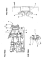
- This apparatus comprises four extruders (b) and one extruding head (c).
- the head (c) comprises a pair of movable parts (c2), and a base part (c1) immovably fixed to a support frame.
- the four extruders (b) are arranged vertically and the four ends thereof are attached to the base part (c1).
- the rubber compounds (g) fed from the extruders (b) are led to a extruder die (e) through passages (d) as shown in Fig.10(c) .
- the movable parts (c2) are each supported pivotally around a vertical axis (i) so as to be opened outward like a French window in order to clean up the passages (d) and do maintenance.
- an object of the present invention to provide an apparatus for manufacturing a strip of rubber compounds, in which the extruder head and its auxiliary equipment such as clamp and stopper can be reduced in size, to reduce equipment cost and waste of rubber compounds and also improve the maintainability, handling, cleaning of rubber passage and the like.
- an apparatus for manufacturing a strip of rubber compounds comprises four extruders of rubber compounds and a single extruder head having an extruding nozzle, the extruder head comprising an extruder die assembly and a main body.
- the invention is characterized in that the main body is provided with a recess in which said extruder die assembly is mounted, in that the main body is composed of a pair of laterally-spaced lateral blocks each having an upper inner face and a lower inner face, the lateral blocks (11) being immovably supported, and a central block disposed between the opposed upper inner faces of the lateral blocks, and a pair of laterally-spaced sub blocks disposed beneath the lateral blocks and having an upper face contacting said lower inner face, in that the central block have a bottom face and a pair of v-form side faces extending in a V-shaped formation down to lateral ends of the bottom face, in that the above-mentioned opposed upper inner faces of the lateral blocks extend in the same V-shaped formation as the V-form side faces so as to fit to the V-form side faces of the central block, in that the lateral blocks are each provided with a tip end surface extending between the upper inner face and lower inner face and the sub blocks each provided with an inner side face extending from the
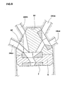
- Fig.9(a) shows a tread rubber G1 for a pneumatic tire having five sections Ya-Yd: a section Ya of a rubber compound ga so called cap tread rubber defining the tread face of the tire; a section Yb of a less heat build-up rubber compound gb so called tread base rubber extending along the underside of the cap tread rubber; a section Yc of a rubber compound gc so called under tread rubber being superior in adhesion to a tread reinforcing cord layer (such as belt, breaker and band) and extending along the underside of the tread base rubber to improve the adhesion between the cord layer and tread base rubber; and a pair of sections Yd of a rubber compound gd so called wing rubber to improve adhesion with sidewall rubber disposed on both sides of the tread.
- Fig.9(b) shows a sidewall rubber G2 for a pneumatic tire having four sections Ya-Yd.
- the rubber strip G1, G2 has the sections formed from the different rubber compounds.
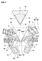
- the V-shaped central block 10 has: a small undersurface S1; and a pair of v-form side faces 15 extending in a V-shaped formation down to both of the lateral ends of the undersurface S1.
- the first die-support base 32 has:
- the second die-support base 33 has a guide passage 39 which leads the second rubber compound g2 coming from the outlet 37o to the final die 7.
- the final die 7 has a forming passage 40 which has an inlet at the upper end thereof into which the second rubber compounds g2 flows and an extruding nozzle at the lower end.
- the nozzle has a shape accord with the finished sectional shape of the tread rubber G1, and the tread rubber strip is extruded from the nozzle 41.
Landscapes
- Engineering & Computer Science (AREA)
- Mechanical Engineering (AREA)
- Manufacturing & Machinery (AREA)
- Extrusion Moulding Of Plastics Or The Like (AREA)
Claims (5)
- Vorrichtung zum Herstellen eines Streifens aus Kautschukmischungen, umfassend
vier Extruder (2a, 2b, 2c, 2d) von Kautschukmischungen (ga, gb, gc, gd)und
einen einzigen Extruderkopf (3), der eine Extrudierdüse (41) aufweist, wobei der Extruderkopf (3)
eine Extruderwerkzeuganordnung (6) und
einen Hauptkörper (4) umfasst,
dadurch gekennzeichnet, dass
der Hauptkörper mit einer Ausnehmung (5) versehen ist, in der die Extruderwerkzeuganordnung montiert ist,
dass der Hauptkörper (4) aus
einem Paar lateral beabstandeten lateralen Blöcken (11), die jeweils eine obere innere Fläche (16) und eine untere innere Fläche (17) aufweisen, wobei die lateralen Blöcke (11) unbeweglich abgestützt sind, und
einem zentralen Block (10), der zwischen den entgegengesetzten oberen inneren Flächen (16) der lateralen Blöcke angeordnet ist, und
einem Paar lateral beabstandeten Teilblöcken (13) zusammengesetzt ist, die unterhalb der lateralen Blöcke (11) angeordnet sind und eine obere Fläche (19) aufweisen, die die untere innere Fläche (17) berührt,
dass der zentrale Block (10)
eine Unterseitenfläche (S1) und
ein Paar Seitenflächen (15) mit V-Form aufweist, die sich in einer V-förmigen Ausgestaltung nach unten bis zu lateralen Enden der Unterseitenfläche (S1) erstrecken,
dass die entgegengesetzten oberen inneren Flächen (16) der lateralen Blöcke (11) sich in der gleichen V-förmigen Ausgestaltung wie die Seitenflächen (15) mit V-Form erstrecken, um in die Seitenflächen (15) mit V-Form des zentralen Blocks zu passen,
dass die lateralen Blöcke (11) jeweils mit einer Stirnendoberfläche (S2) versehen sind, die sich zwischen der oberen inneren Fläche (16) und der unteren inneren Fläche (17) erstreckt, und die Teilblöcke (13) jeweils mit einer inneren Seitenfläche (S3) versehen sind, die sich von der oberen Fläche (19) erstreckt, und die Ausnehmung (5) als eine Ausnehmung mit offenem Boden durch die Stirnendoberflächen (S2), die inneren Seitenflächen (S3) und der Unterseitenfläche (S1) gebildet ist,
dass die lateralen Blöcke (11) jeweils auf der anderen Seite von der oberen inneren Fläche (16) und der unteren inneren Fläche (17) mit einer oberen Befestigungsfläche (21 U) und einer unteren Befestigungsfläche (21 L) versehen sind, an welchen jeweils zwei der vier Extruder (2a, 2b, 2c, 2d) angebracht sind,
dass ein oberer Vorformungskanal (24Ua, 24Ub) vorgesehen ist, der sich von jeder der oberen Befestigungsflächen (21 U) bis zu der Ausnehmung (5) erstreckt und eine Trennebene zwischen der Seitenfläche (15) mit V-Form und der oberen inneren Fläche (16) aufweist,
dass ein unterer Vorformungskanal (24Lc, 24Ld) vorgesehen ist, der sich von jeder der unteren Befestigungsflächen (21 L) bis zu der Ausnehmung (5) erstreckt und eine Trennebene zwischen der unteren inneren Fläche (17) und der oberen Fläche (19) aufweist, und
dass der zentrale Block (10) beweglich in Relation zu den lateralen Blöcken (11) abgestützt ist, um die oberen Vorformungskanäle (24Ua und 24Ub) durch die Trennebene zwischen der Seitenfläche (15) mit V-Form und der oberen inneren Fläche (16) zu öffnen, und
dass die Teilblöcke (13) in Relation zu den lateralen Blöcken (11) beweglich abgestützt sind, um die unteren Vorformungskanäle (24Lc und 24Ld) durch die Trennebene zwischen der unteren inneren Fläche (17) und der oberen Fläche (19) zu öffnen. - Vorrichtung nach Anspruch 1, wobei
das Paar laterale Blöcke (11) rechte und linke laterale Blöcke (11) umfasst, die durch ein geeignetes Mittel (22) unbeweglich abgestützt sind, wobei der V-förmige zentrale Block (10) und die Teilblöcke (13) im Gegensatz zu den lateralen Blöcken (11) beweglich abgestützt sind,
wobei jeder der Teilblöcke (13) in der Auf- und Abrichtung aus einer oberen geschlossenen Position in eine untere offene Position durch Gelenke (26) beweglich abgestützt ist, und ein Ende (P) jedes Gelenks (26) an dem lateralen Block (11) angelenkt ist,
wobei die Teilblöcke (13) nach unten um das angelenkte Ende (P) in die untere offene Position bewegt werden können, so dass sich die obere Fläche (19) jedes Teilblocks (13) von der unteren inneren Fläche (17) des lateralen Blocks (11) trennt, und
wobei die Teilblöcke (13) nach oben in die obere geschlossene Position bewegt werden können, so dass die obere Seite (19) fest mit der unteren inneren Fläche (17) in Kontakt steht. - Vorrichtung nach Anspruch 1, wobei
in jedem der lateralen Blöcke die obere Befestigungsfläche und die untere Befestigungsfläche unterschiedliche Neigungen aufweisen. - Vorrichtung nach Anspruch 1, wobei
die oberen Vorformungskanäle (24Ua und 24Ub) in der Unterseitenfläche (S1) geöffnet sind, und
die unteren Vorformungskanäle (24Lc und 24Ld) jeweils in den Stirnendoberflächen (S2) geöffnet sind. - Vorrichtung nach Anspruch 1, wobei
einer der oberen Vorformungskanäle (24Ua und 24Ub) und einer der unteren Vorformungskanäle (24Lc und 24Ld) in einer der Stirnendoberflächen (S2) geöffnet sind.
Applications Claiming Priority (2)
| Application Number | Priority Date | Filing Date | Title |
|---|---|---|---|
| JP2004170219 | 2004-06-08 | ||
| JP2004170219A JP4283732B2 (ja) | 2004-06-08 | 2004-06-08 | ゴム成形装置 |
Publications (3)
| Publication Number | Publication Date |
|---|---|
| EP1604802A2 EP1604802A2 (de) | 2005-12-14 |
| EP1604802A3 EP1604802A3 (de) | 2012-10-10 |
| EP1604802B1 true EP1604802B1 (de) | 2014-12-31 |
Family
ID=34934819
Family Applications (1)
| Application Number | Title | Priority Date | Filing Date |
|---|---|---|---|
| EP05007553.0A Expired - Lifetime EP1604802B1 (de) | 2004-06-08 | 2005-04-06 | Vorrichtung zur Herstellung von Gummistreifen |
Country Status (4)
| Country | Link |
|---|---|
| US (1) | US7311505B2 (de) |
| EP (1) | EP1604802B1 (de) |
| JP (1) | JP4283732B2 (de) |
| CN (1) | CN1706622B (de) |
Families Citing this family (25)
| Publication number | Priority date | Publication date | Assignee | Title |
|---|---|---|---|---|
| US7281917B2 (en) * | 2004-12-01 | 2007-10-16 | Patwin Plastics, Inc. | Extrusion/reaction injection molding system |
| PT103380B (pt) * | 2005-11-09 | 2007-09-13 | Univ Do Minho | Linha de extrusão laboratorial para a produção de filme tubular convencional e biorientado, com comutação simples entre as duas técnicas |
| JP4851876B2 (ja) * | 2006-07-18 | 2012-01-11 | 住友ゴム工業株式会社 | ゴム押出方法、及びゴム押出装置 |
| DE102009048980A1 (de) * | 2009-10-09 | 2011-04-14 | Troester Gmbh & Co. Kg | Spritzkopf sowie eine mit einem solchen Spritzkopf ausgestattete Extrusionsvorrichtung |
| CN102173043A (zh) * | 2011-01-21 | 2011-09-07 | 江门市多快好省机械有限公司 | 一种流延膜挤出机 |
| JP6148124B2 (ja) * | 2013-09-04 | 2017-06-14 | 東洋ゴム工業株式会社 | ゴム押出成型用ダイ、タイヤ成型用ゴム部品、及び、タイヤ成型用ゴム部品の製造方法 |
| JP6235863B2 (ja) * | 2013-10-28 | 2017-11-22 | 住友ゴム工業株式会社 | ゴム押出し装置、及びゴム押出体の製造方法 |
| CN103753792B (zh) * | 2013-12-31 | 2016-06-29 | 湖州凯博电子线缆有限公司 | 线缆绝缘层双色共挤设备的配色料供应装置 |
| DE102014117068B4 (de) | 2014-11-21 | 2020-04-23 | KraussMaffei Extrusion GmbH | Mehrfach-Strangpresskopf sowie Laufprofil-Herstellvorrichtung zum Herstellen von Laufprofilen von Fahrzeugreifen |
| DE102015108707B4 (de) * | 2015-06-02 | 2020-07-30 | KraussMaffei Extrusion GmbH | Reifenstreifen-Extrusionsvorrichtung zum Herstellen von Lauf- und/oder Seitenstreifen für Reifen und Verfahren zum Herstellen eines Lauf- oder Seitenstreifens eines Reifens |
| KR101594420B1 (ko) * | 2015-12-16 | 2016-02-16 | 주식회사 우성기공 | 교차 압출형 타이어 압출기 |
| JP6232114B1 (ja) * | 2016-10-25 | 2017-11-15 | 中田エンヂニアリング株式会社 | 押出ヘッド及び押出装置 |
| FR3061061A1 (fr) | 2016-12-22 | 2018-06-29 | Compagnie Generale Des Etablissements Michelin | Installation d’extrusion comportant une tete d’extrusion perfectionnee |
| FR3061062A1 (fr) | 2016-12-22 | 2018-06-29 | Compagnie Generale Des Etablissements Michelin | Installation d’extrusion comportant une tete d’extrusion perfectionnee |
| JP7189656B2 (ja) | 2017-02-08 | 2022-12-14 | 住友ゴム工業株式会社 | ゴム押出し装置及びゴム押出し方法 |
| DE102017214756A1 (de) | 2017-08-23 | 2019-02-28 | Continental Reifen Deutschland Gmbh | Vorform-Vorrichtung zum Positionieren von extrudierten Kautschukmischungen und ein die Vorform-Vorrichtung aufweisendes Extruder-Form-System zum Ausformen von extrudierten Kautschukmischungen zu einem Gesamtkautschukelement sowie eine entsprechende Extruderanlage |
| FR3077026B1 (fr) * | 2018-01-23 | 2021-01-08 | Continental Reifen Deutschland Gmbh | Prefiliere de sortie pour la fabrication de bandes de roulement |
| JP7024477B2 (ja) * | 2018-02-13 | 2022-02-24 | 住友ゴム工業株式会社 | タイヤの製造方法及びタイヤ |
| FR3084844B1 (fr) | 2018-06-27 | 2021-07-09 | Michelin & Cie | Installation d'extrusion pour bande de profiles en melanges elastomeriques |
| CN109514829B (zh) * | 2018-12-13 | 2024-06-25 | 软控股份有限公司 | 挤出系统及胎胚加工方法 |
| CN110253852B (zh) * | 2019-06-19 | 2021-04-06 | 桂林电子科技大学 | 折叠式宽幅胶片挤出模设计方法 |
| CN110549580B (zh) * | 2019-08-01 | 2021-07-27 | 上海佳谐精密模具有限公司 | 一种汽车密封条挤出机头 |
| US11338490B1 (en) | 2021-04-09 | 2022-05-24 | Bbs Corporation | Blown film coextrusion line with polygonal extruder arrangement |
| US11173642B1 (en) * | 2021-04-09 | 2021-11-16 | Bbs Corporation | Blown film coextrusion line with polygonal extruder arrangement |
| US11511474B1 (en) | 2021-05-17 | 2022-11-29 | Henry G. Schirmer | Modular disk coextrusion die with melt channeling disk |
Citations (2)
| Publication number | Priority date | Publication date | Assignee | Title |
|---|---|---|---|---|
| DE3506257C1 (de) * | 1985-02-22 | 1986-04-30 | Hermann Berstorff Maschinenbau Gmbh, 3000 Hannover | Aufklappbarer Mehrfach-Strangpresskopf zum Herstellen von Laufstreifenprofilen fuer die Reifenherstellung |
| US6695606B1 (en) * | 1998-01-29 | 2004-02-24 | The Goodyear Tire & Rubber Company | Extrudate shrinkage control and reduction |
Family Cites Families (2)
| Publication number | Priority date | Publication date | Assignee | Title |
|---|---|---|---|---|
| DE3238284C2 (de) * | 1982-10-15 | 1986-08-07 | Hermann Berstorff Maschinenbau Gmbh, 3000 Hannover | Strangpreßkopf zum Herstellen von Flachprofilen aus verschiedenen Gummi- oder Kunststoffmischungen |
| DE3638623C1 (de) * | 1986-11-12 | 1987-10-22 | Berstorff Gmbh Masch Hermann | Strangpresskopf zum Herstellen von aus verschiedenen Kautschukmischungen bestehenden Laufstreifen fuer Autoreifen |
-
2004
- 2004-06-08 JP JP2004170219A patent/JP4283732B2/ja not_active Expired - Lifetime
-
2005
- 2005-04-06 EP EP05007553.0A patent/EP1604802B1/de not_active Expired - Lifetime
- 2005-04-11 US US11/102,696 patent/US7311505B2/en not_active Expired - Fee Related
- 2005-05-13 CN CN2005100714727A patent/CN1706622B/zh not_active Expired - Fee Related
Patent Citations (2)
| Publication number | Priority date | Publication date | Assignee | Title |
|---|---|---|---|---|
| DE3506257C1 (de) * | 1985-02-22 | 1986-04-30 | Hermann Berstorff Maschinenbau Gmbh, 3000 Hannover | Aufklappbarer Mehrfach-Strangpresskopf zum Herstellen von Laufstreifenprofilen fuer die Reifenherstellung |
| US6695606B1 (en) * | 1998-01-29 | 2004-02-24 | The Goodyear Tire & Rubber Company | Extrudate shrinkage control and reduction |
Also Published As
| Publication number | Publication date |
|---|---|
| US7311505B2 (en) | 2007-12-25 |
| CN1706622A (zh) | 2005-12-14 |
| CN1706622B (zh) | 2011-09-28 |
| JP2005349597A (ja) | 2005-12-22 |
| EP1604802A2 (de) | 2005-12-14 |
| JP4283732B2 (ja) | 2009-06-24 |
| EP1604802A3 (de) | 2012-10-10 |
| US20050271761A1 (en) | 2005-12-08 |
Similar Documents
| Publication | Publication Date | Title |
|---|---|---|
| EP1604802B1 (de) | Vorrichtung zur Herstellung von Gummistreifen | |
| IT9020036A1 (it) | Stampo e metodo per la vulcanizzazione di pneumatici e metodo per fabbricare stampi | |
| CN101010182A (zh) | 多层挤压件用挤压设备和用该设备制造多层挤压件的方法 | |
| KR102343891B1 (ko) | 타이어 반제품 제조용 압출 장치 | |
| CN210651813U (zh) | 流量可调节的共挤分配器 | |
| US9339965B2 (en) | Extruding device | |
| CN105313292B (zh) | 具有定幅系统的多歧管挤出模具及其使用方法 | |
| EP1240994B1 (de) | Vorrichtung und Verfahren zum Extrudieren von unvulkanisiertem Kautschuk | |
| JPH06122142A (ja) | 共押出用フラットダイ | |
| JP3578965B2 (ja) | 異形成形品の製造方法およびその装置 | |
| EP3774276B1 (de) | Extrusionsvorrichtung mit wenigstens einer lochplatte | |
| CN201291580Y (zh) | 装配精度高的塑料异型材挤出模模头 | |
| CN213968355U (zh) | 一种四出太阳能边框铝型材挤压模具 | |
| CN2407922Y (zh) | 一种塑料多层共挤机头装置 | |
| CN104070659A (zh) | 多层塑料建筑模板用挤出模头 | |
| JPH02286217A (ja) | 押出成形用複合アダプタ | |
| CN210148678U (zh) | 一种载带的共挤成型模具 | |
| CN222246018U (zh) | 挤出机头和复合挤出装置 | |
| JP3242691U (ja) | 製造装置、ゴムコンパウンドシートの製造装置、及び、ゴムコンパウンドシート | |
| CN222662603U (zh) | 吹塑机模头框及吹塑机 | |
| CN115008719B (zh) | 一种拼接共挤机头及具有该机头的挤出设备 | |
| CN217528751U (zh) | 一种铝型材挤压模具 | |
| KR20250062723A (ko) | 멀티층을 가지는 타이어 사이드월 제조용 압출 다이 | |
| CN202088387U (zh) | 一种母带厚度调节钢塑结构壁管带材成型模具 | |
| CN220546017U (zh) | 一种货架护套及其挤出模具 |
Legal Events
| Date | Code | Title | Description |
|---|---|---|---|
| PUAI | Public reference made under article 153(3) epc to a published international application that has entered the european phase |
Free format text: ORIGINAL CODE: 0009012 |
|
| AK | Designated contracting states |
Kind code of ref document: A2 Designated state(s): AT BE BG CH CY CZ DE DK EE ES FI FR GB GR HU IE IS IT LI LT LU MC NL PL PT RO SE SI SK TR |
|
| AX | Request for extension of the european patent |
Extension state: AL BA HR LV MK YU |
|
| PUAL | Search report despatched |
Free format text: ORIGINAL CODE: 0009013 |
|
| AK | Designated contracting states |
Kind code of ref document: A3 Designated state(s): AT BE BG CH CY CZ DE DK EE ES FI FR GB GR HU IE IS IT LI LT LU MC NL PL PT RO SE SI SK TR |
|
| AX | Request for extension of the european patent |
Extension state: AL BA HR LV MK YU |
|
| RIC1 | Information provided on ipc code assigned before grant |
Ipc: B29C 47/14 20060101ALI20120904BHEP Ipc: B29C 47/56 20060101AFI20120904BHEP Ipc: B29C 47/06 20060101ALI20120904BHEP |
|
| 17P | Request for examination filed |
Effective date: 20130306 |
|
| AKX | Designation fees paid |
Designated state(s): DE IT |
|
| 17Q | First examination report despatched |
Effective date: 20140205 |
|
| GRAP | Despatch of communication of intention to grant a patent |
Free format text: ORIGINAL CODE: EPIDOSNIGR1 |
|
| INTG | Intention to grant announced |
Effective date: 20140807 |
|
| GRAS | Grant fee paid |
Free format text: ORIGINAL CODE: EPIDOSNIGR3 |
|
| GRAA | (expected) grant |
Free format text: ORIGINAL CODE: 0009210 |
|
| AK | Designated contracting states |
Kind code of ref document: B1 Designated state(s): DE IT |
|
| REG | Reference to a national code |
Ref country code: DE Ref legal event code: R096 Ref document number: 602005045545 Country of ref document: DE Effective date: 20150219 |
|
| REG | Reference to a national code |
Ref country code: DE Ref legal event code: R097 Ref document number: 602005045545 Country of ref document: DE |
|
| PLBE | No opposition filed within time limit |
Free format text: ORIGINAL CODE: 0009261 |
|
| STAA | Information on the status of an ep patent application or granted ep patent |
Free format text: STATUS: NO OPPOSITION FILED WITHIN TIME LIMIT |
|
| 26N | No opposition filed |
Effective date: 20151001 |
|
| REG | Reference to a national code |
Ref country code: DE Ref legal event code: R079 Ref document number: 602005045545 Country of ref document: DE Free format text: PREVIOUS MAIN CLASS: B29C0047560000 Ipc: B29C0048490000 |
|
| PGFP | Annual fee paid to national office [announced via postgrant information from national office to epo] |
Ref country code: DE Payment date: 20200325 Year of fee payment: 16 |
|
| PGFP | Annual fee paid to national office [announced via postgrant information from national office to epo] |
Ref country code: IT Payment date: 20200312 Year of fee payment: 16 |
|
| REG | Reference to a national code |
Ref country code: DE Ref legal event code: R119 Ref document number: 602005045545 Country of ref document: DE |
|
| PG25 | Lapsed in a contracting state [announced via postgrant information from national office to epo] |
Ref country code: DE Free format text: LAPSE BECAUSE OF NON-PAYMENT OF DUE FEES Effective date: 20211103 |
|
| PG25 | Lapsed in a contracting state [announced via postgrant information from national office to epo] |
Ref country code: IT Free format text: LAPSE BECAUSE OF NON-PAYMENT OF DUE FEES Effective date: 20200406 |
|
| PG25 | Lapsed in a contracting state [announced via postgrant information from national office to epo] |
Ref country code: IT Free format text: LAPSE BECAUSE OF NON-PAYMENT OF DUE FEES Effective date: 20210406 |