EP1605832B1 - Apparat zum zeitweiligen halten von körpergewebe - Google Patents
Apparat zum zeitweiligen halten von körpergewebe Download PDFInfo
- Publication number
- EP1605832B1 EP1605832B1 EP03723718A EP03723718A EP1605832B1 EP 1605832 B1 EP1605832 B1 EP 1605832B1 EP 03723718 A EP03723718 A EP 03723718A EP 03723718 A EP03723718 A EP 03723718A EP 1605832 B1 EP1605832 B1 EP 1605832B1
- Authority
- EP
- European Patent Office
- Prior art keywords
- arm
- base member
- tension
- rotatable
- pivot
- Prior art date
- Legal status (The legal status is an assumption and is not a legal conclusion. Google has not performed a legal analysis and makes no representation as to the accuracy of the status listed.)
- Expired - Lifetime
Links
Images




Classifications
-
- A—HUMAN NECESSITIES
- A61—MEDICAL OR VETERINARY SCIENCE; HYGIENE
- A61B—DIAGNOSIS; SURGERY; IDENTIFICATION
- A61B17/00—Surgical instruments, devices or methods
- A61B17/02—Surgical instruments, devices or methods for holding wounds open, e.g. retractors; Tractors
-
- A—HUMAN NECESSITIES
- A61—MEDICAL OR VETERINARY SCIENCE; HYGIENE
- A61B—DIAGNOSIS; SURGERY; IDENTIFICATION
- A61B17/00—Surgical instruments, devices or methods
- A61B17/02—Surgical instruments, devices or methods for holding wounds open, e.g. retractors; Tractors
- A61B2017/0237—Surgical instruments, devices or methods for holding wounds open, e.g. retractors; Tractors for heart surgery
- A61B2017/0243—Surgical instruments, devices or methods for holding wounds open, e.g. retractors; Tractors for heart surgery for immobilizing local areas of the heart, e.g. while it beats
-
- A—HUMAN NECESSITIES
- A61—MEDICAL OR VETERINARY SCIENCE; HYGIENE
- A61B—DIAGNOSIS; SURGERY; IDENTIFICATION
- A61B17/00—Surgical instruments, devices or methods
- A61B17/28—Surgical forceps
- A61B17/29—Forceps for use in minimally invasive surgery
- A61B2017/2901—Details of shaft
- A61B2017/2904—Details of shaft curved, but rigid
-
- A—HUMAN NECESSITIES
- A61—MEDICAL OR VETERINARY SCIENCE; HYGIENE
- A61B—DIAGNOSIS; SURGERY; IDENTIFICATION
- A61B17/00—Surgical instruments, devices or methods
- A61B17/28—Surgical forceps
- A61B17/29—Forceps for use in minimally invasive surgery
- A61B2017/2901—Details of shaft
- A61B2017/2905—Details of shaft flexible
-
- A—HUMAN NECESSITIES
- A61—MEDICAL OR VETERINARY SCIENCE; HYGIENE
- A61B—DIAGNOSIS; SURGERY; IDENTIFICATION
- A61B17/00—Surgical instruments, devices or methods
- A61B17/30—Surgical pincettes, i.e. surgical tweezers without pivotal connections
- A61B2017/306—Surgical pincettes, i.e. surgical tweezers without pivotal connections holding by means of suction
- A61B2017/308—Surgical pincettes, i.e. surgical tweezers without pivotal connections holding by means of suction with suction cups
-
- A—HUMAN NECESSITIES
- A61—MEDICAL OR VETERINARY SCIENCE; HYGIENE
- A61B—DIAGNOSIS; SURGERY; IDENTIFICATION
- A61B90/00—Instruments, implements or accessories specially adapted for surgery or diagnosis and not covered by any of the groups A61B1/00 - A61B50/00, e.g. for luxation treatment or for protecting wound edges
- A61B90/50—Supports for surgical instruments, e.g. articulated arms
- A61B2090/508—Supports for surgical instruments, e.g. articulated arms with releasable brake mechanisms
-
- A—HUMAN NECESSITIES
- A61—MEDICAL OR VETERINARY SCIENCE; HYGIENE
- A61B—DIAGNOSIS; SURGERY; IDENTIFICATION
- A61B90/00—Instruments, implements or accessories specially adapted for surgery or diagnosis and not covered by any of the groups A61B1/00 - A61B50/00, e.g. for luxation treatment or for protecting wound edges
- A61B90/50—Supports for surgical instruments, e.g. articulated arms
- A61B90/57—Accessory clamps
- A61B2090/571—Accessory clamps for clamping a support arm to a bed or other supports
-
- A—HUMAN NECESSITIES
- A61—MEDICAL OR VETERINARY SCIENCE; HYGIENE
- A61B—DIAGNOSIS; SURGERY; IDENTIFICATION
- A61B90/00—Instruments, implements or accessories specially adapted for surgery or diagnosis and not covered by any of the groups A61B1/00 - A61B50/00, e.g. for luxation treatment or for protecting wound edges
- A61B90/50—Supports for surgical instruments, e.g. articulated arms
Definitions
- the present invention generally relates to surgery on body tissues and organs. More specifically, the present invention relates to devices for engaging an organ, e.g. for positioning an organ in a desired orientation or for temporarily immobilizing a local area of tissue subject to motion, such as the heart wall, which permits a surgical procedure to be performed on that local area of tissue.
- an organ e.g. for positioning an organ in a desired orientation or for temporarily immobilizing a local area of tissue subject to motion, such as the heart wall, which permits a surgical procedure to be performed on that local area of tissue.
- Coronary artery disease remains the leading cause of morbidity and mortality in Western societies.
- a number of approaches have been developed for treating coronary artery disease. In less severe cases, it is often sufficient to merely treat the symptoms with pharmaceuticals or to treat the underlying causes of the disease with lifestyle modification.
- the coronary blockage can be treated endovascularly using techniques such as balloon angioplasty, atherectomy, laser ablation, stents, and the like. In cases where these approaches have failed or are likely to fail, it is often necessary to perform a coronary artery bypass graft procedure.
- the coronary artery bypass graft procedure traditionally required a heart-lung or cardiopulmonary bypass. Due to the risks incurred during cardiopulmonary bypass, beating heart bypass surgery techniques have been developed to allow coronary artery bypass without cardiopulmonary bypass.
- Several systems are presently available which attempt to immobilize epicardial tissue in the immediate vicinity of an anastomosis site through a pressure stabilizer employing a simple mechanical fork. Such a device stabilizes the heart by pressing a fork downwards onto the heart surface.
- the fork is typically mounted to an elongated arm, which in turn is typically mounted to a retractor, holding the patient's ribs apart to create an operative window.
- Angular movement of the arm relative to the retractor in some cases is accomplished by means of a turret, which may be clamped in its desired rotational position. Longitudinal movement of the arm relative to the retractor is typically allowed as well, and clamping mechanisms are typically provided to allow clamping of the arm to the turret and locking of the fork relative to the arm.
- Exemplary pressure stabilization devices are disclosed in US Patent No.6,876,332, issued to Looney and US Patent No.6,036,641, issued to Taylor, et al. .
- Suction stabilization systems such as the Medtronic Octopus® Tissue Stabilizer (available from Medtronic, Inc., Minneapolis, Minnesota USA), instead employ a comparatively long, flexible, articulating arm carrying a pair of suction paddles or pods at its distal end.
- the arm is typically secured to a retractor, holding the patient's ribs apart to create an operative window.
- the pods are placed on either side of the anastomosis site and suction is applied to grip and immobilize the surface of the heart. Thereafter, tension is applied along the length of the arm to lock the arm in its position and to lock the position of the pods relative to the Arm.
- Medtronic's device is generally disclosed in US Patent No.
- suction retractors are often employed to position the heart to allow access to the desired anastomosis site.
- the Medtronic Starfish TM device and the Guidant Axius TM Expose TM device are examples of commercially available suction retractors. These devices employ a single, larger suction pod to engage the heart, typically in the vicinity of the heart apex.
- the suction pod is carried by a flexible arm, which, like the suction stabilizers discussed above, also may be locked into a desired configuration by tension applied along their length.
- the application of tension to the arm may also serve to lock a carrier for the suction pod relative to the arm to fix the suction pod in a desired orientation relative to the arm, as in the Guidant device.
- the Medtronic device is described in US Patent Application SN 09/679,294 , filed 6/12/01 by Keogh, et al. for a " Method and System for Organ Positioning and Stabilization.
- the Guidant device is described in the brochure "Axius TM Expose TM Device, Instructions for Use, Guidant Corp., 2001 , P/N 30462, Rev. A.
- Other suction retractors are described in US Patent No. 6,019,772, issued to Spence, et al. and PCT Publication No. WO 01/17437 by Peng .
- the present invention provides an improved tissue engagement device such as a suction stabilizer or retractor according to claim 1, claim 2, or claim 3.
- FIG. 1A is a perspective view of a preferred embodiment of the invention.
- a flexible, articulating arm 20 is attached to base assembly 24 on the proximal end of the arm, and terminates with tightening/spreading mechanism 21 at the distal end of the arm.
- On the opposite, more proximal, end of base assembly 24 is handle 23, which operates to lock the arm in position, as discussed in more detail below.
- Extending distally beyond tightening/spreading mechanism 21 is a plurality (as shown, two) of suction paddles or pods 22.
- the suction pods 22 can be connected to a vacuum line by a conventional vacuum line connection 25.
- Each pod and its suction ports may be constructed in any acceptable manner, such as that used in the Medtronic Octopus TM tissue stabilizer.
- Clamp 26 is designed to attach the entire device to conventional surgical retractors or other equipment located in a fixed relation to the operative site.
- the preferred embodiment shown in FIG. 1A is illustrative but not intended to be limiting insofar as the scope of the invention is concerned.
- the handle 23 is shown in a preferred and highly stylized embodiment, but any device that performs the functions of the handle as described below would suffice.
- Articulating arm 20 comprises a plurality of "ball and socket" links 120, as illustrated in FIGS. 1B and 1C , discussed below.
- the links of articulating arm 20 are covered with a thin walled elastomeric sheath, as disclosed in the above cited '047 application.
- the sheath serves to prevent fragile sutures from catching on the edges where the links join.
- the sheath is preferably manufactured of silicone rubber, although other materials, such as latex rubber or polyurethane or even collagen, may also be used.
- FIG. 1B is a cross sectional view of a link used in the arm of the present invention.
- each link 120 has a hole 123 that passes through its center.
- Each link 120 comprises, on its distal end, a spherical protrusion 121; and on its proximal end, a spherical indentation 122.
- the spherical shapes of adjacent links are nearly identical, such that the links rotate smoothly against one another provided they are not under undue tension with each other.
- FIG. 1C is a partial view of a section of the links and cable showing the engagement of the cable with the sidewall of the links as the arm is bent.
- a cable 40 passes through hole of all of the links and is connected between the handle 23 and the tightening/spreading mechanism 21. Rotation of handle 23 tightens the cable and causes the links to hold against each other in place. Immobilization of the links relative to each other during tightening of the cable is facilitated by the shape of the hole 123. As seen, hole is flared, having a larger opening with the surface of the spherical protrusion 121 and a smaller opening through the surface of the spherical indentation 122.
- the links as seen in FIG.
- the links may vary in size along the length of the arm, with the links in the most proximal portion of the arm being largest, and the links in the most distal portion being the smallest.
- the links are fabricated out of a highly rigid engineered thermoplastic or of a metal such as stainless steel.
- the cable is preferably a multi-stranded stainless steel cable, having between approximately 7 to 19 strands.
- the links and cable may also be manufactured from other materials, including any other suitable metals or highly engineered polymers including any number of available liquid crystal polymers for the links, as well as many other types of cables, including bundle stranded, braided or cabled titanium as well as Kevlar TM for the cable.
- Some embodiments may also employs a textured surface molded or otherwise formed into the spherical features of the links.
- the texturing causes an increase in coefficient of friction between the adjacent spherical surfaces. This has the highly desirable benefit of increasing overall system stiffness. Examples of such surfaces are also disclosed in the above cited '047 application.
- FIG. 2A is an exploded drawing illustrating the various functional components of the base assembly 24 of the suction stabilizer illustrated in FIG. 1A .
- the base assembly 24 includes a fixed portion to be mounted to a surgical retractor or other structure having a fixed location relative to the patient and a rotatable portion or turret, rotatable relative to the fixed portion of the base.
- the fixed portion of the base assembly includes pivot mount 240, cover 241, lever 200 and associated cam rod 202, springs 244 and a cam pin, not shown in this view.
- the rotatable portion of the base assembly includes the turret, comprising first and second turret halves 206 and 216 and hinge pin 208, and the tensioning mechanism comprising handle 23, threaded shaft 222, washers 226 and sleeve 228 which, as assembled, is mounted to the proximal end of the tension cable 40 ( FIG. 1C ).
- a spherical projection 204 is formed on the distal end of turret half 206, which is inserted in the corresponding spherical recess of the first link 120 ( FIG. 1A ) of the flexible arm.
- Pivot mount 240 carries the turret pivot 242, which takes the form of a disk topping a cylindrical section extending upward and at an angle from the pivot mount 240.
- First and second turret halves 206 and 216 when assembled, are mounted around the turret pivot 242, allowing the turret and attached flexible arm to pivot relative to the fixed portion of the base assembly.
- the first and second turret halves 202 and 216 are provided with grooved portions 207, 217, adapted to engage with the disk-shaped top portion of turret pivot 242, allowing rotation but preventing removal of the first and second turret members 206 and 216.
- Turret halves 206 and 216 are connected to one another by means of hinge pin 208.
- hinge pin 208 When assembled, hinge pin 208 passes through bore 212 in the second turret half 216, through bore 210 in the first turret half 206 and then is anchored in bore 214 of the second turret half 216.
- turret halves 206 and 216 may pivot relative to one another.
- the dimensions of the internally formed grooves in turret halves 206 and 216 are such that when the two components are pivoted around pin 208 such that their lower extremities are in close proximity to one another, they correspondingly clamp inwardly around the turret pivot 242, locking the turret rotationally into position relative to the fixed portion of the base assembly.
- projection 215 When assembled, projection 215 is located in a corresponding recess in turret half 206, maintaining the turret halves in alignment.
- the mechanism for tensioning cable 40 ( FIG. 1 C) is carried by the turret and includes handle 23, threaded shaft 222, washers 226 and sleeve 228. When assembled, sleeve 228 is tightly crimped to the end of the tension cable 40 which, in the device as assembled, extends through the internal bore 224 of threaded member 222, through first and second turret halves 206 and 216 and out the opening 250 on the distal surface 204 of the first turret component 206.
- rotation of handle 23 causes tension to be applied to the cable 40, tightening the elements of the flexible arm relative to one another to a fixed position.
- tightening of the cable also causes first and second turret halves 206 and 216 to pivot toward one another, causing them to clamp circumferentially around turret pivot 242.
- the distal extremity of the threaded member 220 is provided with a hexagonally shaped distal portion 220, which is located in a corresponding hexagonally configured recess 218 in the proximal portion of the second turret half 216.
- Threaded member 222 is free to slide within this recess, but cannot rotate.
- washers 226 are located within the proximal end of the first turret half 216, and provide a bearing surface against which handle 23 rotates.
- Handle 23 is provided with internal threading corresponding to the external threading on member 222.
- Rotation of handle 23 thus causes proximal movement of member 222 against sleeve 228, in turn causing proximal movement of the cable 40, correspondingly tightening the components of the articulating arm and the turret, to affix them in their desired positions.
- Resilient tabs 223 of handle 23 cooperate with corresponding notches formed in the second turret half 216 to prevent over-rotation of the handle 23 and consequent detachment of the handle. This aspect of the operation of the tensioning mechanism is discussed in more detail below in conjunction with FIG. 2E .
- proximal movement of cable 40 also serves to stabilize the location of the spreading mechanism 21 at the distal portion of the arm (as illustrated in FIG. 1A ) as well as causing the suction pods 22 (also illustrated in FIG. 1A ) to move outward relative to one another.
- rotation of the knob 23 accomplishes four functions as a result of tensioning the cable, including clamping of the turret to the fixed portion of the base, locking the flexible arm in its then present configuration, locking the position of the tightening/spreading mechanism 21 and pods 20 relative to the distal end of the flexible arm, and shortly thereafter or concurrently, spreading the suction pods 220 apart from one another to stretch the heart tissue located between the pods.
- FIG. 2C The structural relationship of the various components of FIG. 2A is illustrated in more detail in FIG. 2C , discussed below.
- clamp 26 Mounted to the fixed portion of the base assembly is sliding clamp 26.
- Clamp 26 is provided with inwardly directed tabs 234 and is also provided with two upwardly extending projections 236.
- projections 236 are located adjacent the distal ends of springs 244, which lie in downwardly extending grooves formed in the lower surface of pivot mount 240 and urge clamp 26 distally.
- Handle 200 and cam rod 202 also make up a portion of the clamping mechanism, passing through bore 248 in the clamp 26. Functional operation of the clamp 232 is described in more detail in conjunction with FIGs. 2C and 2D , discussed below.
- FIG. 2B is a plan view of the distal surface of the base assembly 24 after assembly. All numbered components illustrated correspond to identically numbered components in FIG. 2A . In this view, it can be seen that the first and second turret halves 206 and 216, respectively, are mounted closely adjacent to one another and around the turret pivot 242 (not visible in this view). FIG. 2B also illustrates the line along which the cross-section of FIG. 2C is taken.
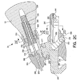
- FIG. 2C is a sectional view through the base assembly 24 illustrated in FIGs. 2A and 2B .
- the functional inter-relationship of the components of the base assembly can better be appreciated. All components correspond to identically numbered components in FIGs. 2A and 2B .
- turret halves 206 and 216 are shown mounted to one another by means of hinge pin 208, and the inter-relation of the internal circumferential grooves207, 217 in turret halves 206 and 216 can be appreciated. These grooves are shown as located closely adjacent to the outer surface of the pivot 242. Movement of the lower portions of the turret halves 206 and 216 toward one another due to tension provided by the cable 40 tightly clamps the turret to the turret pivot 242.
- Handle 23 is shown with its threaded inner surface engaging the threaded member 222 and its distal surface lying adjacent washers 226, located in a recess formed in the proximal end of turret component 216.
- the hexagonally shaped distal portion of threaded member 222 is shown lying within a correspondingly configured lumen 264 formed within turret half 216, allowing for longitudinal movement of threaded member 220 but not rotational movement.
- Sleeve 226 is shown located within the handle 26, adjacent the proximal end of threaded member 220 and is mounted to the proximal end of the tension cable 40
- Pivot mount 240 is provided with a downwardly extending projection having a proximally facing angled surface 252, corresponding to a distally facing angled surface 254 on the distal end of clamp 26.
- a portion of a retractor is located between these two slanted surfaces, and clamp 26 is moved distally as far as possible so that that portion of the retractor is held between pivot mount 240 and clamp 26.
- Cam pin 256 is located within an angled bore 260 formed in clamp 26, having its lower extremity located proximal to its upper extremity.
- Pin 256 extends through and is located slidably within a downwardly extending slot 262, formed in pivot mount 240. Although not shown in this view, the enlarged head portion 258 of pin 256 bears downwardly along the upper surface 238 of the pivot mount 240.
- Cam rod 202 has its camming surface located within a cross bore in the pin 256, configured so that rotation of the handle 200 and associated cam rod 202 pulls the pin downward relative to the pivot mount 240 and is correspondingly pulls clamp 26 upward into tight contact with pivot mount 240. Because pin 256 and bore 260 are angled less than 90 degrees relative to the axis along which the clamp 26 slides, rotation of the cam rod 202 by means of lever 200 ( FIG. 2B ) also causes a slight distal movement of clamp 26 relative to the pivot base 240, tightening it against the associated retractor as well. Cover 241 is shown mounted to the pivot mount 240, covering the slot 262 in which the pin 256 is mounted.
- FIG. 2D is a partial cross-section through the fixed portion of the base assembly 24 illustrated in FIG. 2C .
- the pivot mount 240 is provided with two downwardly extending longitudinal grooves 268, in which springs 244 are mounted.
- the distal ends of these springs bear against the upwardly extending projections 236 ( FIG. 2A ) on clamp 26 and the proximal ends of these springs bear against projections located within grooves 268 in order to urge clamp 26 in a distal direction relative to the pivot mount 240.
- cam pin 266 shows its enlarged head portion 258 riding along the upper surface 238 of the pivot mount 240. All other numbered components correspond to identically numbered components in the figures above.
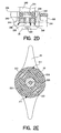
- FIG. 2E is a partial cross-section through the proximal portion of the second turret half 216, illustrating the inter relation of the resilient tabs 223 on knob 23 and the internal lumen formed in turret half 216.
- resilient tabs 223 are compressed inward against the inner surface of the lumen in the proximal portion of turret half 216.
- Formed adjacent to the proximal edge of the turret half 216 are two triangular depressions 211, formed to correspond to the free ends of the resilient tabs 233.
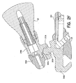
- FIG. 2F illustrates a cross-sectional view through an alternative embodiment to the base assembly illustrated in FIG. 2C .
- Pivot mount 240A is provided with a spherical pivot 242A rather than a disk shaped pivot as in the embodiment of FIG. 2C .
- turret halves 206A and 216A are provided with spherical recesses 207A and 217A, rather than circumferential slots as in the embodiment of FIG. 2C .
- This alternative embodiment provides a base assembly with a higher profile, but allows for increased adjustability of the position of the turret relative to the base, as compared to the embodiment illustrated in FIG. 2C . All other aspects of operation of the device correspond to those discussed above in conjunction with FIG. 2C .
- FIG. 3A is a plan view of the proximal end of the tightening/spreading mechanism 21 of the suction stabilizer illustrated in FIG. 1A .
- the tension cable 40 is visible in cross-section, exiting through bore in the proximal surface of the tightening/spreading mechanism 21.
- a spherical recess 302 is formed in the proximal surface of tightening/spreading mechanism 21, which receives the corresponding spherical surface of the last link 120 ( FIG. 1A ) of the flexible arm.
- Located concentrically within the vacuum connector 25 is a metallic tube 304, which functions to deliver vacuum to the suction pods 22, mounted to the spreading/tightening mechanism 21.
- FIG. 3A also illustrates the cross-sectional line along which the view of FIG. 3B is taken.
- FIG. 3B shows the spreading/tightening mechanism 21 of FIG. 1 , in conjunction with the vacuum pods 22.
- the spreading/tightening mechanism 21 includes a first molded plastic component 309.
- a metal ball 332, located at the distal end of cable 230 is located within a corresponding generally cylindrical recess 335 formed in plastic component 309.
- Ball 334 may be provided with a silicone coating to reduce friction.
- a portion of the recess 332 is formed as an angled surface 330, which also engages a portion of the proximal surface of ball 334.
- proximal movement of cable 230 caused by rotation of handle 23, as discussed above, causes the proximal surface of ball 30 to bear against the angled surface 330, causing deformation of member 309 and corresponding spreading of the suction pods 22, relative to one another.
- Indentations 337, molded into component 309 serve to define hinge points.
- Suction pods 22 correspond generally to those described in conjunction with the '047 application, cited above. However, rather than delivering vacuum individually to each pod, only a single vacuum line is required, coupled to vacuum connector 25. Distribution of vacuum to both pods is accomplished by means of a cross bore 320, molded into the plastic component 310 which forms the body of suction pods 22.
- Malleable metal tubes 304 and 306 are shown located within longitudinally aligned bores within components 309 and 310.
- Tube 304 extends to the vacuum connector 305, and serves as the vacuum source for both pods 22.
- the proximal end of tube 306 is capped by ball 308, and the recess adjacent to it is backfilled, for example with silicone rubber.
- the distal ends of both tubes 304 and 306 are similarly capped with balls 307 and backfilled.
- Cross bore 320 extends all the way through the molded plastic component 309. However, it is sealed at its ends by means of the tubular projections 340 and 342 of component 309. After assembly, the slight recesses 322 and 324 may be filled with silicone rubber.
- Malleable tubes 304 and 306 are formed such that each is provided with a laterally directed opening 328, 326 which as assembled aligns with the cross bore 320, providing a mechanism for communicating vacuum applied to tube 304 to tube 306, and thereby evenly applied to both suction pods 22.
- Vacuum applied to tube 304 is delivered to cup shaped recesses in each of the pods, indicated at 316 and 318, by means of bores 312 and 314, in a fashion similar to that as employed in the presently available Medtronic devices.
- FIG. 3C is a side plan view of the spreading/tightening mechanism 21 and suction pods 22 illustrated in FIG. 3B .
- Numbered components correspond to identically numbered components in FIG. 3B .
- the general configuration of the pods 22 and of the cup shaped recesses 314, illustrated in broken outline, can be seen.
- the lower surface of the pods is molded to define a generally arcuate surface 338 for improving adhesion of the pods to the heart surface.
- the stabilizer is disclosed as a stabilizer having a flexible, articulating arm.
- the invention may similarly be practiced in a suction retractor with an articulating arm.
- certain aspects of the invention might also be used fully practiced in the context of a stabilizer or retractor with a rigid arm.
- the ability to simultaneously rotationally lock the turret relative to the fixed portion of the base assembly in conjunction with adjustment of the angular position of the spreading/tightening assembly relative to the arm or adjustment of the position of the suction pod of a retractor relative to the arm would still be desirable.
- the ability to simultaneously lock the turret rotationally relative to the fixed portion of the base and spread the pods 22 would still be valuable.
- the spreading/tightening mechanism could also usefully be employed in a stabilizer with a rigid arm.
- the disclosed embodiments of the invention take the form of a suction stabilizer, inclusion of the ability to simultaneously adjust the position of the turret relative to the fixed portion of the base and adjust the position of the tissue contact members in a pressure stabilization device would also be of use in a pressure stabilizer.
Landscapes
- Health & Medical Sciences (AREA)
- Life Sciences & Earth Sciences (AREA)
- Surgery (AREA)
- Molecular Biology (AREA)
- General Health & Medical Sciences (AREA)
- Biomedical Technology (AREA)
- Heart & Thoracic Surgery (AREA)
- Medical Informatics (AREA)
- Nuclear Medicine, Radiotherapy & Molecular Imaging (AREA)
- Animal Behavior & Ethology (AREA)
- Engineering & Computer Science (AREA)
- Public Health (AREA)
- Veterinary Medicine (AREA)
- Surgical Instruments (AREA)
- Supplying Of Containers To The Packaging Station (AREA)
- Electrotherapy Devices (AREA)
- Investigating Or Analyzing Materials By The Use Of Electric Means (AREA)
- Measurement Of The Respiration, Hearing Ability, Form, And Blood Characteristics Of Living Organisms (AREA)
- Control And Other Processes For Unpacking Of Materials (AREA)
Claims (11)
- Eine Vorrichtung zum Erfassen von Gewebe, die folgendes umfasst:einen verlängerten Arm (20), der zur Entfaltung mehrerer Konfigurationen flexibel ist, mit einem proximalen Ende und einem distalen Ende und einer Längsachse;einen Mechanismus zum Erfassen von Gewebe (21, 22), der an dem distalen Ende des Arms angebracht ist;eine Grundanordnung (24), umfassend ein ortsfestes Grundelement und ein drehbares Grundelement, angebracht an dem proximalen Ende des Arms, das zur Bereitstellung einer Drehung der Achse des Arms an seinem proximalen Ende relativ zu dem ortsfesten Grundelement drehbar ist;ein Spannelement (40), das sich durch das drehbare Grundelement und den Arm erstreckt; undeinen Spannmechanismus, angebracht an dem drehbaren Grundelement, der operativ zum Aufbringen eines Zugs mit dem Spannelement gekoppelt ist, um gleichzeitig eine Dreharretierung des drehbaren Grundelements an dem ortsfesten Grundelement und eine Arretierung des flexiblen Arms in seiner dann gegenwärtigen Konfiguration zu bewirken.
- Eine Vorrichtung zum Erfassen von Gewebe, die folgendes umfasst:einen verlängerten Arm (20) mit einem proximalen Ende und einem distalen Ende und einer Längsachse;einen Mechanismus zum Erfassen von Gewebe (21, 22), der an dem distalen Ende des Arms drehbar angebracht ist;eine Grundanordnung (24), umfassend ein ortsfestes Grundelement und ein drehbares Grundelement, angebracht an dem proximalen Ende des Arms, das zur Bereitstellung einer Drehung der Achse des Arms an seinem proximalen Ende relativ zu dem ortsfesten Grundelement drehbar ist;ein Spannelement (40), das sich durch das drehbare Grundelement und den Arm zu dem Mechanismus zum Erfassen von Gewebe erstreckt; undeinen Spannmechanismus, angebracht an dem drehbaren Grundelement, der operativ zum Aufbringen eines Zugs mit dem Spannelement gekoppelt ist, um gleichzeitig eine Dreharretierung des drehbaren Grundelements an dem ortsfesten Grundelement und eine Arretierung der Position des Mechanismus zum Erfassen von Gewebe relativ zu dem Arm zu bewirken.
- Eine Vorrichtung zum Erfassen von Gewebe, die folgendes umfasst:einen verlängerten Arm (20) mit einem proximalen Ende und einem distalen Ende und einer Längsachse;einen Mechanismus zum Erfassen von Gewebe, angebracht an dem distalen Ende des Arms, der erste und zweite Gewebekontaktelemente (22), die sich von dem distalen Ende des Arms erstrecken, und Mittel (21) zum Spreizen der Gewebekontaktelemente weg voneinander als Reaktion auf einen aufgebrachten Zug, umfasst;eine Grundanordnung (24), umfassend ein ortsfestes Grundelement und ein drehbares Grundelement, angebracht an dem proximalen Ende des Arms, das zur Bereitstellung einer Drehung der Achse des Arms an seinem proximalen Ende relativ zu dem ortsfesten Grundelement drehbar ist;ein Spannelement (40), das sich durch das drehbare Grundelement und den Arm zu dem Mechanismus zum Erfassen von Gewebe erstreckt; undeinen Spannmechanismus, angebracht an dem drehbaren Grundelement, der operativ zum Aufbringen eines Zugs mit dem Spannelement gekoppelt ist, um gleichzeitig eine Dreharretierung des drehbaren Grundelements an dem ortsfesten Grundelement und ein Aufspreizen der Gewebekontaktelemente weg voneinander zu bewirken.
- Eine Vorrichtung nach Anspruch 1 oder Anspruch 2 oder Anspruch 3, wobei das ortsfeste Grundelement ein Gelenk umfasst und wobei das drehbare Grundelement um das Gelenk herum angebracht ist und wobei das Aufbringen eines Zugs auf das Spannelement das drehbare Element um das Gelenk herum zusammendrückt.
- Eine Vorrichtung nach Anspruch 4, wobei das drehbare Grundelement zwei Komponenten umfasst, die drehbar aneinander angebracht sind, und wobei das Aufbringen eines Zugs auf das Spannelement die beiden Komponenten relativ zueinander zum Zusammendrücken der Komponenten um das Gelenk herum dreht.
- Eine Vorrichtung nach Anspruch 5, wobei das Gelenk einen Vorsprung aus dem ortsfesten Grundelement mit einer kreisförmigen peripheren Oberfläche umfasst und wobei das Aufbringen eines Zugs auf das Spannelement die beiden Komponenten relativ zueinander zum Zusammendrücken der Komponenten um die kreisförmige periphere Oberfläche des Gelenks herum dreht.
- Eine Vorrichtung nach Anspruch 6, wobei die kreisförmige periphere Oberfläche des Gelenks eine zylindrische Oberfläche ist.
- Eine Vorrichtung nach Anspruch 6, wobei die kreisförmige periphere Oberfläche des Gelenks eine kugelförmige Oberfläche ist.
- Eine Vorrichtung nach Anspruch 1 oder Anspruch 2, wobei der Mechanismus zum Erfassen von Gewebe ein Saugblatt umfasst.
- Eine Vorrichtung nach Anspruch 9, wobei der Mechanismus zum Erfassen von Gewebe zwei Saugblätter umfasst.
- Eine Vorrichtung nach Anspruch 3, wobei die Gewebekontaktelemente Saugblätter sind.
Priority Applications (2)
| Application Number | Priority Date | Filing Date | Title |
|---|---|---|---|
| EP08017318A EP2008594B1 (de) | 2003-03-13 | 2003-03-13 | Vorrichtung zum temporären Erfassen von Körpergewebe |
| AT08017318T ATE506013T1 (de) | 2003-03-13 | 2003-03-13 | Vorrichtung zum temporären erfassen von körpergewebe |
Applications Claiming Priority (1)
| Application Number | Priority Date | Filing Date | Title |
|---|---|---|---|
| PCT/US2003/007491 WO2004082487A1 (en) | 2003-03-13 | 2003-03-13 | Apparatus for temporarily engaging body tissue |
Related Child Applications (1)
| Application Number | Title | Priority Date | Filing Date |
|---|---|---|---|
| EP08017318A Division EP2008594B1 (de) | 2003-03-13 | 2003-03-13 | Vorrichtung zum temporären Erfassen von Körpergewebe |
Publications (2)
| Publication Number | Publication Date |
|---|---|
| EP1605832A1 EP1605832A1 (de) | 2005-12-21 |
| EP1605832B1 true EP1605832B1 (de) | 2009-07-01 |
Family
ID=33029237
Family Applications (2)
| Application Number | Title | Priority Date | Filing Date |
|---|---|---|---|
| EP08017318A Expired - Lifetime EP2008594B1 (de) | 2003-03-13 | 2003-03-13 | Vorrichtung zum temporären Erfassen von Körpergewebe |
| EP03723718A Expired - Lifetime EP1605832B1 (de) | 2003-03-13 | 2003-03-13 | Apparat zum zeitweiligen halten von körpergewebe |
Family Applications Before (1)
| Application Number | Title | Priority Date | Filing Date |
|---|---|---|---|
| EP08017318A Expired - Lifetime EP2008594B1 (de) | 2003-03-13 | 2003-03-13 | Vorrichtung zum temporären Erfassen von Körpergewebe |
Country Status (8)
| Country | Link |
|---|---|
| EP (2) | EP2008594B1 (de) |
| JP (1) | JP4364807B2 (de) |
| AT (2) | ATE434978T1 (de) |
| AU (1) | AU2003230631A1 (de) |
| DE (2) | DE60328229D1 (de) |
| DK (1) | DK1605832T3 (de) |
| ES (2) | ES2327628T3 (de) |
| WO (1) | WO2004082487A1 (de) |
Families Citing this family (16)
| Publication number | Priority date | Publication date | Assignee | Title |
|---|---|---|---|---|
| US7779845B2 (en) | 2005-08-05 | 2010-08-24 | Ethicon Endo-Surgery, Inc. | Method and apparatus for endoscopically performing gastric reduction surgery |
| WO2007127818A2 (en) * | 2006-04-26 | 2007-11-08 | Medtronic, Inc. | Methods and devices for stabilizing tissue |
| JP4716333B2 (ja) * | 2006-12-22 | 2011-07-06 | 住友ベークライト株式会社 | 冠状動脈バイパス術用処置具 |
| FR2915873B1 (fr) * | 2007-05-09 | 2009-08-14 | Artmedis Sarl | Dispositif de bras articule porte-outil destine a porter un instrument chirurgical. |
| KR100940990B1 (ko) | 2007-12-24 | 2010-02-05 | 이영삼 | 핸들의 조립구조를 개선한 심장수술에 사용되는 안정화장치 |
| BR112012032039B1 (pt) * | 2010-06-14 | 2020-12-15 | Maquet Cardiovascular Llc | Instrumentos cirúrgicos |
| KR101230142B1 (ko) * | 2010-10-20 | 2013-02-05 | 이영삼 | 심장 안정화 장치 |
| US9581190B2 (en) | 2015-03-30 | 2017-02-28 | Hilel Richman | Adjustable support arm |
| EP3508136B1 (de) * | 2016-08-31 | 2022-10-12 | Beijing Surgerii Technology Co., Ltd. | Flexibles chirurgisches instrument mit strukturellen knochen in einer gekreuzten anordnung |
| CN106236269B (zh) | 2016-08-31 | 2018-09-04 | 北京术锐技术有限公司 | 一种多自由度的柔性手术工具 |
| WO2018041204A1 (zh) * | 2016-08-31 | 2018-03-08 | 北京术锐技术有限公司 | 一种柔性手术工具系统 |
| WO2018041218A1 (zh) * | 2016-08-31 | 2018-03-08 | 北京术锐技术有限公司 | 柔性手术工具系统 |
| US11684432B2 (en) | 2016-08-31 | 2023-06-27 | Beijing Surgerii Robotics Company Limited | Sterilizable flexible surgical instrument system |
| CN106308936B (zh) | 2016-08-31 | 2018-12-07 | 北京术锐技术有限公司 | 一种包含驱动骨的柔性手术工具系统 |
| CN106344157B (zh) * | 2016-08-31 | 2019-04-23 | 北京术锐技术有限公司 | 一种可消毒的柔性手术工具系统 |
| GR1009622B (el) * | 2018-09-11 | 2019-10-23 | Γεωργιος Παντελη Σολομωνιδης | Βοηθητικο εργαλειο ιατρου |
Family Cites Families (13)
| Publication number | Priority date | Publication date | Assignee | Title |
|---|---|---|---|---|
| US5836311A (en) | 1995-09-20 | 1998-11-17 | Medtronic, Inc. | Method and apparatus for temporarily immobilizing a local area of tissue |
| US5727569A (en) | 1996-02-20 | 1998-03-17 | Cardiothoracic Systems, Inc. | Surgical devices for imposing a negative pressure to fix the position of cardiac tissue during surgery |
| CA2197614C (en) | 1996-02-20 | 2002-07-02 | Charles S. Taylor | Surgical instruments and procedures for stabilizing the beating heart during coronary artery bypass graft surgery |
| WO1998049944A1 (en) | 1997-05-02 | 1998-11-12 | Pilling Weck Incorporated | Adjustable supporting bracket having plural ball and socket joints |
| US6007486A (en) | 1997-10-07 | 1999-12-28 | Ethicon Endo-Surgery, Inc. | Tissue stabilization device for use during surgery having a segmented shaft |
| WO1999037213A1 (en) | 1998-01-23 | 1999-07-29 | United States Surgical Corporation | Surgical instrument |
| US6113534A (en) | 1998-03-19 | 2000-09-05 | Koros; Tibor B. | Adjustable heart surface stabilizer |
| AU758587B2 (en) * | 1998-09-15 | 2003-03-27 | Medtronic, Inc. | Method and apparatus for temporarily immobilizing a local area of tissue |
| US6019772A (en) | 1998-09-21 | 2000-02-01 | Arteria Medical Sciences, Inc. | Atherectomy device |
| US6506149B2 (en) | 1999-09-07 | 2003-01-14 | Origin Medsystems, Inc. | Organ manipulator having suction member supported with freedom to move relative to its support |
| US6471644B1 (en) * | 2000-04-27 | 2002-10-29 | Medtronic, Inc. | Endoscopic stabilization device and method of use |
| WO2002028287A1 (en) * | 2000-10-02 | 2002-04-11 | Medtronic, Inc. | Method and apparatus for temporarily immobilizing a local area of tissue |
| US6876332B1 (en) | 2003-11-11 | 2005-04-05 | Realtek Semiconductor Corp. | Multiple-frequency antenna structure |
-
2003
- 2003-03-13 EP EP08017318A patent/EP2008594B1/de not_active Expired - Lifetime
- 2003-03-13 DK DK03723718T patent/DK1605832T3/da active
- 2003-03-13 AT AT03723718T patent/ATE434978T1/de active
- 2003-03-13 AU AU2003230631A patent/AU2003230631A1/en not_active Abandoned
- 2003-03-13 EP EP03723718A patent/EP1605832B1/de not_active Expired - Lifetime
- 2003-03-13 DE DE60328229T patent/DE60328229D1/de not_active Expired - Lifetime
- 2003-03-13 AT AT08017318T patent/ATE506013T1/de active
- 2003-03-13 ES ES03723718T patent/ES2327628T3/es not_active Expired - Lifetime
- 2003-03-13 ES ES08017318T patent/ES2361588T3/es not_active Expired - Lifetime
- 2003-03-13 DE DE60336866T patent/DE60336866D1/de not_active Expired - Lifetime
- 2003-03-13 WO PCT/US2003/007491 patent/WO2004082487A1/en not_active Ceased
- 2003-03-13 JP JP2004569639A patent/JP4364807B2/ja not_active Expired - Lifetime
Also Published As
| Publication number | Publication date |
|---|---|
| EP2008594B1 (de) | 2011-04-20 |
| EP2008594A2 (de) | 2008-12-31 |
| ES2361588T3 (es) | 2011-06-20 |
| DK1605832T3 (da) | 2009-11-09 |
| DE60336866D1 (de) | 2011-06-01 |
| EP1605832A1 (de) | 2005-12-21 |
| ATE506013T1 (de) | 2011-05-15 |
| JP2006513785A (ja) | 2006-04-27 |
| WO2004082487A1 (en) | 2004-09-30 |
| AU2003230631A1 (en) | 2004-10-11 |
| EP2008594A3 (de) | 2009-06-24 |
| DE60328229D1 (de) | 2009-08-13 |
| ES2327628T3 (es) | 2009-11-02 |
| ATE434978T1 (de) | 2009-07-15 |
| JP4364807B2 (ja) | 2009-11-18 |
Similar Documents
| Publication | Publication Date | Title |
|---|---|---|
| US6866628B2 (en) | Apparatus for temporarily engaging body tissue | |
| US6758809B2 (en) | Surgical tool for engagement of body tissue | |
| EP2008594B1 (de) | Vorrichtung zum temporären Erfassen von Körpergewebe | |
| EP0993806B1 (de) | Einrichtung zur zeitlichen Immobilisierung von abgegrentzten Gewebeflächen | |
| US7137949B2 (en) | Surgical instrument | |
| JP4072217B2 (ja) | 冠状動脈迂回手術中に心臓を安定に保つ外科用装置及び処置 | |
| US6648818B2 (en) | Articulation member for use in a surgical apparatus | |
| US6264605B1 (en) | Surgical instrument | |
| CN1610524A (zh) | 用于保持稳定组织装置的分段臂 | |
| KR101415280B1 (ko) | 이식물 연결장치 | |
| WO1999015069A2 (en) | Surgical apparatus and method | |
| US12082835B2 (en) | Surgical device including two-cable hemispherical grasper |
Legal Events
| Date | Code | Title | Description |
|---|---|---|---|
| PUAI | Public reference made under article 153(3) epc to a published international application that has entered the european phase |
Free format text: ORIGINAL CODE: 0009012 |
|
| 17P | Request for examination filed |
Effective date: 20051013 |
|
| AK | Designated contracting states |
Kind code of ref document: A1 Designated state(s): AT BE BG CH CY CZ DE DK EE ES FI FR GB GR HU IE IT LI LU MC NL PT RO SE SI SK TR |
|
| AX | Request for extension of the european patent |
Extension state: AL LT LV MK |
|
| DAX | Request for extension of the european patent (deleted) | ||
| GRAP | Despatch of communication of intention to grant a patent |
Free format text: ORIGINAL CODE: EPIDOSNIGR1 |
|
| GRAS | Grant fee paid |
Free format text: ORIGINAL CODE: EPIDOSNIGR3 |
|
| GRAA | (expected) grant |
Free format text: ORIGINAL CODE: 0009210 |
|
| AK | Designated contracting states |
Kind code of ref document: B1 Designated state(s): AT BE BG CH CY CZ DE DK EE ES FI FR GB GR HU IE IT LI LU MC NL PT RO SE SI SK TR |
|
| REG | Reference to a national code |
Ref country code: GB Ref legal event code: FG4D |
|
| REG | Reference to a national code |
Ref country code: CH Ref legal event code: EP |
|
| REG | Reference to a national code |
Ref country code: IE Ref legal event code: FG4D |
|
| REF | Corresponds to: |
Ref document number: 60328229 Country of ref document: DE Date of ref document: 20090813 Kind code of ref document: P |
|
| REG | Reference to a national code |
Ref country code: ES Ref legal event code: FG2A Ref document number: 2327628 Country of ref document: ES Kind code of ref document: T3 |
|
| REG | Reference to a national code |
Ref country code: DK Ref legal event code: T3 |
|
| PG25 | Lapsed in a contracting state [announced via postgrant information from national office to epo] |
Ref country code: SI Free format text: LAPSE BECAUSE OF FAILURE TO SUBMIT A TRANSLATION OF THE DESCRIPTION OR TO PAY THE FEE WITHIN THE PRESCRIBED TIME-LIMIT Effective date: 20090701 |
|
| NLV1 | Nl: lapsed or annulled due to failure to fulfill the requirements of art. 29p and 29m of the patents act | ||
| PG25 | Lapsed in a contracting state [announced via postgrant information from national office to epo] |
Ref country code: FI Free format text: LAPSE BECAUSE OF FAILURE TO SUBMIT A TRANSLATION OF THE DESCRIPTION OR TO PAY THE FEE WITHIN THE PRESCRIBED TIME-LIMIT Effective date: 20090701 Ref country code: EE Free format text: LAPSE BECAUSE OF FAILURE TO SUBMIT A TRANSLATION OF THE DESCRIPTION OR TO PAY THE FEE WITHIN THE PRESCRIBED TIME-LIMIT Effective date: 20090701 Ref country code: SE Free format text: LAPSE BECAUSE OF FAILURE TO SUBMIT A TRANSLATION OF THE DESCRIPTION OR TO PAY THE FEE WITHIN THE PRESCRIBED TIME-LIMIT Effective date: 20090701 |
|
| PG25 | Lapsed in a contracting state [announced via postgrant information from national office to epo] |
Ref country code: NL Free format text: LAPSE BECAUSE OF FAILURE TO SUBMIT A TRANSLATION OF THE DESCRIPTION OR TO PAY THE FEE WITHIN THE PRESCRIBED TIME-LIMIT Effective date: 20090701 |
|
| PG25 | Lapsed in a contracting state [announced via postgrant information from national office to epo] |
Ref country code: BG Free format text: LAPSE BECAUSE OF FAILURE TO SUBMIT A TRANSLATION OF THE DESCRIPTION OR TO PAY THE FEE WITHIN THE PRESCRIBED TIME-LIMIT Effective date: 20091001 Ref country code: PT Free format text: LAPSE BECAUSE OF FAILURE TO SUBMIT A TRANSLATION OF THE DESCRIPTION OR TO PAY THE FEE WITHIN THE PRESCRIBED TIME-LIMIT Effective date: 20091102 |
|
| PG25 | Lapsed in a contracting state [announced via postgrant information from national office to epo] |
Ref country code: RO Free format text: LAPSE BECAUSE OF FAILURE TO SUBMIT A TRANSLATION OF THE DESCRIPTION OR TO PAY THE FEE WITHIN THE PRESCRIBED TIME-LIMIT Effective date: 20090701 Ref country code: CZ Free format text: LAPSE BECAUSE OF FAILURE TO SUBMIT A TRANSLATION OF THE DESCRIPTION OR TO PAY THE FEE WITHIN THE PRESCRIBED TIME-LIMIT Effective date: 20090701 |
|
| PLBE | No opposition filed within time limit |
Free format text: ORIGINAL CODE: 0009261 |
|
| STAA | Information on the status of an ep patent application or granted ep patent |
Free format text: STATUS: NO OPPOSITION FILED WITHIN TIME LIMIT |
|
| PG25 | Lapsed in a contracting state [announced via postgrant information from national office to epo] |
Ref country code: SK Free format text: LAPSE BECAUSE OF FAILURE TO SUBMIT A TRANSLATION OF THE DESCRIPTION OR TO PAY THE FEE WITHIN THE PRESCRIBED TIME-LIMIT Effective date: 20090701 |
|
| 26N | No opposition filed |
Effective date: 20100406 |
|
| PG25 | Lapsed in a contracting state [announced via postgrant information from national office to epo] |
Ref country code: MC Free format text: LAPSE BECAUSE OF NON-PAYMENT OF DUE FEES Effective date: 20100331 Ref country code: GR Free format text: LAPSE BECAUSE OF FAILURE TO SUBMIT A TRANSLATION OF THE DESCRIPTION OR TO PAY THE FEE WITHIN THE PRESCRIBED TIME-LIMIT Effective date: 20091002 |
|
| REG | Reference to a national code |
Ref country code: CH Ref legal event code: PL |
|
| GBPC | Gb: european patent ceased through non-payment of renewal fee |
Effective date: 20100313 |
|
| PG25 | Lapsed in a contracting state [announced via postgrant information from national office to epo] |
Ref country code: IE Free format text: LAPSE BECAUSE OF NON-PAYMENT OF DUE FEES Effective date: 20100313 |
|
| PG25 | Lapsed in a contracting state [announced via postgrant information from national office to epo] |
Ref country code: LI Free format text: LAPSE BECAUSE OF NON-PAYMENT OF DUE FEES Effective date: 20100331 Ref country code: CH Free format text: LAPSE BECAUSE OF NON-PAYMENT OF DUE FEES Effective date: 20100331 |
|
| PG25 | Lapsed in a contracting state [announced via postgrant information from national office to epo] |
Ref country code: GB Free format text: LAPSE BECAUSE OF NON-PAYMENT OF DUE FEES Effective date: 20100313 |
|
| PG25 | Lapsed in a contracting state [announced via postgrant information from national office to epo] |
Ref country code: CY Free format text: LAPSE BECAUSE OF FAILURE TO SUBMIT A TRANSLATION OF THE DESCRIPTION OR TO PAY THE FEE WITHIN THE PRESCRIBED TIME-LIMIT Effective date: 20090701 |
|
| PG25 | Lapsed in a contracting state [announced via postgrant information from national office to epo] |
Ref country code: LU Free format text: LAPSE BECAUSE OF NON-PAYMENT OF DUE FEES Effective date: 20100313 Ref country code: HU Free format text: LAPSE BECAUSE OF FAILURE TO SUBMIT A TRANSLATION OF THE DESCRIPTION OR TO PAY THE FEE WITHIN THE PRESCRIBED TIME-LIMIT Effective date: 20100102 |
|
| PG25 | Lapsed in a contracting state [announced via postgrant information from national office to epo] |
Ref country code: TR Free format text: LAPSE BECAUSE OF FAILURE TO SUBMIT A TRANSLATION OF THE DESCRIPTION OR TO PAY THE FEE WITHIN THE PRESCRIBED TIME-LIMIT Effective date: 20090701 |
|
| REG | Reference to a national code |
Ref country code: FR Ref legal event code: PLFP Year of fee payment: 14 |
|
| REG | Reference to a national code |
Ref country code: FR Ref legal event code: PLFP Year of fee payment: 15 |
|
| REG | Reference to a national code |
Ref country code: FR Ref legal event code: PLFP Year of fee payment: 16 |
|
| PGFP | Annual fee paid to national office [announced via postgrant information from national office to epo] |
Ref country code: DE Payment date: 20200218 Year of fee payment: 18 Ref country code: AT Payment date: 20200227 Year of fee payment: 18 Ref country code: DK Payment date: 20200225 Year of fee payment: 18 Ref country code: IT Payment date: 20200218 Year of fee payment: 18 |
|
| PGFP | Annual fee paid to national office [announced via postgrant information from national office to epo] |
Ref country code: BE Payment date: 20200228 Year of fee payment: 18 |
|
| PGFP | Annual fee paid to national office [announced via postgrant information from national office to epo] |
Ref country code: FR Payment date: 20200220 Year of fee payment: 18 |
|
| PGFP | Annual fee paid to national office [announced via postgrant information from national office to epo] |
Ref country code: ES Payment date: 20200401 Year of fee payment: 18 |
|
| REG | Reference to a national code |
Ref country code: DE Ref legal event code: R119 Ref document number: 60328229 Country of ref document: DE |
|
| REG | Reference to a national code |
Ref country code: DK Ref legal event code: EBP Effective date: 20210331 |
|
| REG | Reference to a national code |
Ref country code: AT Ref legal event code: MM01 Ref document number: 434978 Country of ref document: AT Kind code of ref document: T Effective date: 20210313 |
|
| REG | Reference to a national code |
Ref country code: BE Ref legal event code: MM Effective date: 20210331 |
|
| PG25 | Lapsed in a contracting state [announced via postgrant information from national office to epo] |
Ref country code: AT Free format text: LAPSE BECAUSE OF NON-PAYMENT OF DUE FEES Effective date: 20210313 Ref country code: FR Free format text: LAPSE BECAUSE OF NON-PAYMENT OF DUE FEES Effective date: 20210331 Ref country code: DE Free format text: LAPSE BECAUSE OF NON-PAYMENT OF DUE FEES Effective date: 20211001 |
|
| PG25 | Lapsed in a contracting state [announced via postgrant information from national office to epo] |
Ref country code: IT Free format text: LAPSE BECAUSE OF NON-PAYMENT OF DUE FEES Effective date: 20210313 Ref country code: DK Free format text: LAPSE BECAUSE OF NON-PAYMENT OF DUE FEES Effective date: 20210331 |
|
| REG | Reference to a national code |
Ref country code: ES Ref legal event code: FD2A Effective date: 20220523 |
|
| PG25 | Lapsed in a contracting state [announced via postgrant information from national office to epo] |
Ref country code: ES Free format text: LAPSE BECAUSE OF NON-PAYMENT OF DUE FEES Effective date: 20210314 Ref country code: BE Free format text: LAPSE BECAUSE OF NON-PAYMENT OF DUE FEES Effective date: 20210331 |