EP1605997B1 - Nadelschutzvorrichtung für eine spritze, und injektionsvorrichtung mit einer spritze und dieser nadelschutzvorrichtung - Google Patents
Nadelschutzvorrichtung für eine spritze, und injektionsvorrichtung mit einer spritze und dieser nadelschutzvorrichtung Download PDFInfo
- Publication number
- EP1605997B1 EP1605997B1 EP04742360.3A EP04742360A EP1605997B1 EP 1605997 B1 EP1605997 B1 EP 1605997B1 EP 04742360 A EP04742360 A EP 04742360A EP 1605997 B1 EP1605997 B1 EP 1605997B1
- Authority
- EP
- European Patent Office
- Prior art keywords
- support
- needle
- syringe
- protector
- protective support
- Prior art date
- Legal status (The legal status is an assumption and is not a legal conclusion. Google has not performed a legal analysis and makes no representation as to the accuracy of the status listed.)
- Expired - Lifetime
Links
Images




Classifications
-
- A—HUMAN NECESSITIES
- A61—MEDICAL OR VETERINARY SCIENCE; HYGIENE
- A61M—DEVICES FOR INTRODUCING MEDIA INTO, OR ONTO, THE BODY; DEVICES FOR TRANSDUCING BODY MEDIA OR FOR TAKING MEDIA FROM THE BODY; DEVICES FOR PRODUCING OR ENDING SLEEP OR STUPOR
- A61M5/00—Devices for bringing media into the body in a subcutaneous, intra-vascular or intramuscular way; Accessories therefor, e.g. filling or cleaning devices, arm-rests
- A61M5/178—Syringes
- A61M5/31—Details
- A61M5/32—Needles; Details of needles pertaining to their connection with syringe or hub; Accessories for bringing the needle into, or holding the needle on, the body; Devices for protection of needles
- A61M5/3205—Apparatus for removing or disposing of used needles or syringes, e.g. containers; Means for protection against accidental injuries from used needles
- A61M5/321—Means for protection against accidental injuries by used needles
- A61M5/3243—Means for protection against accidental injuries by used needles being axially-extensible, e.g. protective sleeves coaxially slidable on the syringe barrel
- A61M5/3257—Semi-automatic sleeve extension, i.e. in which triggering of the sleeve extension requires a deliberate action by the user, e.g. manual release of spring-biased extension means
-
- A—HUMAN NECESSITIES
- A61—MEDICAL OR VETERINARY SCIENCE; HYGIENE
- A61M—DEVICES FOR INTRODUCING MEDIA INTO, OR ONTO, THE BODY; DEVICES FOR TRANSDUCING BODY MEDIA OR FOR TAKING MEDIA FROM THE BODY; DEVICES FOR PRODUCING OR ENDING SLEEP OR STUPOR
- A61M5/00—Devices for bringing media into the body in a subcutaneous, intra-vascular or intramuscular way; Accessories therefor, e.g. filling or cleaning devices, arm-rests
- A61M5/178—Syringes
- A61M5/31—Details
- A61M5/32—Needles; Details of needles pertaining to their connection with syringe or hub; Accessories for bringing the needle into, or holding the needle on, the body; Devices for protection of needles
- A61M5/3205—Apparatus for removing or disposing of used needles or syringes, e.g. containers; Means for protection against accidental injuries from used needles
- A61M5/321—Means for protection against accidental injuries by used needles
- A61M5/3243—Means for protection against accidental injuries by used needles being axially-extensible, e.g. protective sleeves coaxially slidable on the syringe barrel
- A61M5/3245—Constructional features thereof, e.g. to improve manipulation or functioning
- A61M2005/3247—Means to impede repositioning of protection sleeve from needle covering to needle uncovering position
-
- A—HUMAN NECESSITIES
- A61—MEDICAL OR VETERINARY SCIENCE; HYGIENE
- A61M—DEVICES FOR INTRODUCING MEDIA INTO, OR ONTO, THE BODY; DEVICES FOR TRANSDUCING BODY MEDIA OR FOR TAKING MEDIA FROM THE BODY; DEVICES FOR PRODUCING OR ENDING SLEEP OR STUPOR
- A61M5/00—Devices for bringing media into the body in a subcutaneous, intra-vascular or intramuscular way; Accessories therefor, e.g. filling or cleaning devices, arm-rests
- A61M5/178—Syringes
- A61M5/31—Details
- A61M5/32—Needles; Details of needles pertaining to their connection with syringe or hub; Accessories for bringing the needle into, or holding the needle on, the body; Devices for protection of needles
- A61M5/3205—Apparatus for removing or disposing of used needles or syringes, e.g. containers; Means for protection against accidental injuries from used needles
- A61M5/321—Means for protection against accidental injuries by used needles
- A61M5/3243—Means for protection against accidental injuries by used needles being axially-extensible, e.g. protective sleeves coaxially slidable on the syringe barrel
- A61M5/3271—Means for protection against accidental injuries by used needles being axially-extensible, e.g. protective sleeves coaxially slidable on the syringe barrel with guiding tracks for controlled sliding of needle protective sleeve from needle exposing to needle covering position
- A61M5/3272—Means for protection against accidental injuries by used needles being axially-extensible, e.g. protective sleeves coaxially slidable on the syringe barrel with guiding tracks for controlled sliding of needle protective sleeve from needle exposing to needle covering position having projections following labyrinth paths
Definitions
- This needle protection device conventionally comprises a protective support for receiving the injection syringe.
- the protector is movable relative to the support under the action of the spring.
- Initial retaining means of the protector relative to the support are provided in order to allow the release of the spring at the end of the injection.
- a device according to the preamble of claim 1 is known from WO 01/85239 .
- the needle protection devices are armed, that is to say that the actuating springs of the protectors are compressed.
- the spring can be accidentally released causing the introduction of the needle protector. The device is then unusable.
- the invention as defined in claim 1 is intended to provide a needle protection device whose risks of accidental triggering in the absence of a syringe are reduced.
- the subject of the invention is a protection device of the type defined above, characterized in that it comprises mechanical means for locking the needle protector with respect to the protective support in the direction of release, absence of a syringe body in the duct of the protector support, which mechanical locking means are deactivatable by engagement of a syringe body in the conduit of the protector support.
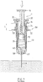
- the invention further relates to an injection device comprising, firstly, a syringe which comprises a needle, a tubular body at the distal end of which is fixed a needle, and an injection piston slidably mounted in the body, and secondly, a needle protection device as described above.
- proximal and distal are synonymous, as well as the terms “distal” and “before”.
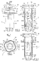
- Syringe 1 is a standard shaped glass syringe for single use. It contains a liquid to be injected, intramuscularly or subcutaneously, to a patient. It comprises for this purpose a body 4, a needle 6 secured to the distal end of the body 4 and a piston 8.
- This piston conventionally comprises a rod 10 provided at its distal end with a buffer 12 visible on the Figure 6A and a support head 14 on which is intended to rest the thumb of the practitioner's hand.
- the body 4 of the syringe has in its proximal portion a neck 16 delimiting circumferentially two diametrically opposed lugs 18, normally intended, especially in the absence of the assembly 2, to form bearing surfaces for the index and middle fingers of the practitioner during the handling of the syringe and the injection of the liquid therein.
- the support 20 comprises a main section 26, substantially cylindrical and of internal diameter substantially equal to the outer diameter of the body 4 of the syringe. This section 26 is extended at its proximal end by a secondary section 28 of larger inside and outside diameters than those of the main section 26, forming a radial shoulder 29.
- the proximal section 28 is provided with means 30 for attachment to the syringe neck 16. More specifically, these means 30 comprise diametrically opposed deformable hooks 32, also visible on the figure 1 . Each of these hooks has a substantially frustoconical ramp surface 32A flaring towards the free end of the section 28, intended to be pushed elastically by the lugs 18 of the syringe neck 16 during the fixing of the support 20 on the syringe 1.
- the hooks 32 are distant from the shoulder 29 by a distance substantially equal to the thickness of the lugs 18. The hooks 32 thus form a clipping means of the syringe neck 16.
- Each groove consists of a first rectilinear portion 38 which extends substantially along the axis XX of the support 20 on a length greater than that of the needle 6, and a second straight portion 40 which extends inclined relative to the same axis XX.
- the inclined portion 40 opens at the proximal end of the first rectilinear portion 38, forming a V whose tip is directed to the proximal side of the assembly 2.
- the main section 26 has at its distal end a first pair of diametrically opposed elastic tongues 42, each located in the extension of the grooves 36 (FIG. figure 5 ).
- These tabs 42 have an inner face 42A of substantially cylindrical shape and an outer face substantially deflectable 42B diverging rearwardly.
- the main section 26 has a pair of diametrically opposed external ramps 44 situated between the elastic tongues 42 along the circumference of the distal end of this section. They have a substantially frustoconical inclined outer surface 44A, diverging forwards, and a substantially planar distal surface 44B. The outer surfaces 44A are thus turned towards the recesses 26A.
- Longitudinal recesses 26A are formed in the main section 26 ( figure 3 ) at the proximal end of these ramps 44.
- axial slots 26B are provided from the distal end of the support, so that before insertion of the body 4 of the syringe 1 into the support 20, these tongues 42 are radially deformable, in particular towards the inside.
- the protective sleeve 22 is of length substantially equal to that of the body 4 of the syringe 1. It consists of two cylindrical sections 46 and 48, the proximal section 46 being of diameter slightly greater than that of the main section 48. These two sections are connect by forming a radial shoulder 49.
- the sleeve 22 has integrally, in its proximal part, an outer collar 50 in the form of two diametrically opposed lugs 52 ( figure 4 ).
- two diametrically opposite pins 54 are integral with the sleeve ( figure 5 ). These two nipples are received and guided in respectively the two grooves 36 of the support 20.
- the support and the sleeve are thus movable relative to each other in translation along their common axis and in limited rotation about the same axis when the pins are in the inclined portions 40.
- the inclined portions 40 then form retention pockets nipples 54, these pockets having a retention depth noted p on the Figure 3 . This depth is measured along the axis of the protector.
- the support 20 and the sleeve 22 are movable between a retracted position of the sleeve, wherein the bulk of the sleeve covers the bulk of the support and the pins 54 are located at the distal end of each of the inclined groove portions 40, as shown on the Figures 2 to 7 , and an extended position of the sleeve in which it extends axially projecting from the support and the nipples are located at the distal end of the straight groove portion 38, as shown in FIGS. Figures 11 to 13 .
- these extreme positions respectively correspond to an injection configuration in which the needle 6 of the syringe 1 is disengaged and intended to be inserted into a patient, and to a protective configuration wherein this needle is surrounded by the protective sleeve 22.
- the proximal portion of the sleeve 22 further comprises internally a pair of deformable longitudinal hooks 56 diametrically opposed. These hooks are delimited in the sleeve 22 by lateral slots. These hooks are connected to the sleeve at their distal end. Each hook has at its proximal free end an inner protuberance.
- each protuberance has a front face 56A of substantially frustoconical shape diverging towards the front of the axis of the sleeve 22. These front faces 56A are thus turned towards the front end of the protector.
- Each front face 56A is adapted to cooperate with an inclined surface 44A formed by the ramps 44 of the support.
- each inner protuberance has an inclined rear face 56B facing the rear end of the protector, and in particular towards the two ears 52.
- These surfaces 56B are generally frustoconical and diverge from each other towards the rear end of the protector.
- the support 20 comprises frustoconical ramps 57 disposed at the rear of the recesses 26A. These ramps are inclined towards the recesses 26A and are adapted to cooperate with the rear inclined faces 56B.
- each hook 56 has an inclined transverse front 56C forming a stop.
- each hook extends immediately opposite the corresponding end of the recess 26A.
- the distance d between the end face 56C of the edge of the recess is less than the depth p of the retention pocket formed of the inclined groove portion 40 in which the pin 54 is received.
- the hooks 56 In the retracted position of the sleeve, the hooks 56 extend inside the recesses 26A formed in the support 20. In the extended position of the sleeve, as shown in FIG. figure 11 , the end faces 56C of the hooks 56 are in axial abutment against the tabs 44, the hooks and tongues thereby forming a rigid locking assembly in the deployed position.
- the sleeve 22 is furthermore provided at its distal end with a ring of deformable tongues 58, the distal edges of which form a substantially circular opening 60 of diameter smaller than the inside diameter of the main section 26 of the support 20.
- the spring 24 is a spiral spring, disposed between the protective sleeve 22 and the protective support 20. More specifically, the spring is housed between the shoulder 29 of the support 20 and the shoulder 49 of the sleeve 22. In the retracted position of the sleeve, the spring 24 is in a compressed state, thus having a decompression energy related to the stiffness of the spring and the difference between the length of the spring at rest and its length, noted L on the Figures 2 to 7 in the compressed state. That is to say that the spring 24 has a threshold of additional compressive force which corresponds to the minimum force necessary to compress the spring further from its initial compressed state. Figures 2 to 7 .
- the stiffness of the spring and / or the initial compression length L are chosen such that this force threshold is greater than the thrust force necessary to move the piston 8 of the syringe 1 over its entire injection stroke. More precisely, the spring force in the locked state is greater than the sum of the injection force, that is to say discharging the liquid outside the needle 6 of the syringe 1, and stripping and sliding forces of the pusher 12 inside the body 4 of the syringe.
- the protection assembly 2 further comprises a cap 66 of generally tubular shape, represented on the figures 1 and 6A .
- the cap 66 is adapted to surround the needle 6 before use of the syringe 1.
- This cap is closed at one of its ends and its opposite end is formed by an annular ring 68 of external diameter adapted to both be conjugate of the 42A surface of the hooks 42 of the support 20 and be greater than the diameter of the opening 60 formed by the tabs 58 of the protective sleeve 22.
- the inner face of this ring 68 is intended to adhere to the glass base 69 of the syringe body 4 where is fixed the needle 6, in particular to ensure a certain tightness to bacteria.
- the end face forms a stop adapted to cooperate with the edge of the recesses 26A to prevent a recoil of the protective sleeve 22 towards the rear end of the support 20.
- the hooks 56 are then in the locking position.
- the glass syringe 1 is pre-filled with a liquid to be injected into a patient.
- This syringe is equipped with the cap 66 which encloses the base 67 of the syringe body 4.
- the syringe and the cap are inserted inside the assembly 2 to form the injection device, as shown in FIGS. Figures 6A and 6B . More specifically, the body 4 of the syringe is displaced substantially axially inside the support 20. When the body 4 of the syringe is engaged in the support 20, and as illustrated in FIG. Figure 6A , the syringe body presses on the rear inclined faces 56B, thus causing the protuberances of the hooks 56 to be effaced outwards.
- the movement of the syringe body in the protector is carried out until the syringe neck 16, indexed by the protuberances 34, engages inside the proximal section 28, deforming the hooks 32 radially outwardly.
- the ears 18 of the syringe neck 16 are then retained axially by the hooks 32, while the peripheral protrusions 34 hold the syringe neck, and therefore the syringe, in rotation relative to the support 20.
- the cap 66 protrudes outside the protective sleeve 22.
- the practitioner When the practitioner is ready to inject the liquid contained in the syringe, he removes the cap 66 by pulling it axially forward. The ring 68 then passes through the opening 60 by deforming the tongues 58. Once the cap 66 has been removed, the tongues 58 return to their initial position. The through hole 60 at the distal end of the sleeve, which is smaller in diameter than the outside diameter of the cap 68, then prevents the cap from being put back in place around the needle. The cooperation of the cap 66 and tabs 58 thus form a means of controlling the first use of the injection device.
- the practitioner then removes the needle from the patient.
- the practitioner exerts an additional pressure on the piston rod 8.
- This pressure must be greater than the predetermined force produced by the spring 24 in the locked state, so that this spring is more compressed and passes from its length L to a length The smallest, as represented on the Figures 8 to 10 .
- the protective sleeve 24 moves axially toward the proximal end of the support 20. The practitioner performs this movement by exerting a corresponding pressure by means of his index finger and his middle finger on the ears 52 of the flange 50 of the sleeve 22.
- the pressure causes, in combination with the translation movement, the rotation of the protective sleeve 22 around the syringe holder 20, the nipples 54 being guided by the inclined groove portions 40. This rotational movement continues until the nipples reach the proximal end of this groove portion 40, i.e. the proximal end of the longitudinal groove portion 38, as visible on the figure 9 .
- the device 2 is then in the unlocking position of the spring 24.
- the pins 54 move in translation within the longitudinal groove portion 38, to the distal end thereof as shown in FIG. figure 13 .
- the translational movement of the protective sleeve 22 relative to the support 20 is controllable by the practitioner, if the latter gradually releases the digital retainer that the collar 50 exerts.
- the hooks 56 borrow the longitudinal recesses 26A of the support, until they slide along the distal ramps 44 of the support, by cooperation of their complementary surfaces 56A and 44A.
- the hooks 56 are held by cooperation of the surfaces 56C and 44B, so that the protective sleeve 22 can not be brought back to its original position.
- the sleeve 22 can not be easily torn off the support 20 since the pins 54 abut against the distal bottom of the longitudinal groove portion 38 (FIG. figure 13 ), the tabs 42 forming this bottom being radially held between the body of the syringe 1 and the protective sleeve 22.
- the injection device according to the invention is thus easy to use, while allowing the practitioner to control the movement of recovery of the needle by the protective sleeve.
- the number of parts of which is constituted the protection assembly 2 represented is reduced to three.
- the device according to the invention is adaptable to different types of syringes, both in terms of shapes and volumes. This device therefore has the advantage of not calling into question the general shape of the syringes used and therefore does not involve any modification of the industrial processes for filling these syringes.
Landscapes
- Health & Medical Sciences (AREA)
- Engineering & Computer Science (AREA)
- Heart & Thoracic Surgery (AREA)
- Vascular Medicine (AREA)
- Anesthesiology (AREA)
- Biomedical Technology (AREA)
- Environmental & Geological Engineering (AREA)
- Hematology (AREA)
- Life Sciences & Earth Sciences (AREA)
- Animal Behavior & Ethology (AREA)
- General Health & Medical Sciences (AREA)
- Public Health (AREA)
- Veterinary Medicine (AREA)
- Infusion, Injection, And Reservoir Apparatuses (AREA)
Claims (7)
- Vorrichtung zum Schutz einer Nadel, aufweisend:- einen Schutz-Halter (20), der einen Tunnel zur Aufnahme eines Spritzenkörpers (4) begrenzt,
einen Nadel-Schutz (22), der bezüglich des Schutz-Halters (20) bewegbar ist zwischen einer Einrückposition und einer Ausrückposition,- eine Druckfeder (24), die zwischen dem Schutz-Halter (20) und dem Nadel-Schutz (22) eingesetzt ist,wobei die Vorrichtung gekennzeichnet ist durch:- wenigstens einen Ansatz (54) des Nadel-Schutzes (22) und wenigstens eine korrespondierende Nut (36) des Schutz-Halters (20), welche den besagten Ansatz aufnimmt und führt,wobei die wenigstens eine Nut aufweist: einen ersten geradlinigen Abschnitt (38), welcher sich im Wesentlichen entlang einer Achse des Schutz-Halters (20) erstreckt über eine Länge, die größer ist als eine Länge der zu schützenden Nadel, und einen zweiten geradlinigen Abschnitt (40), der sich in einer schrägen Weise bezüglich der besagten Achse des Schutz-Halters (20) erstreckt, wobei der erste und der zweite Abschnitt (38, 40) eine V bilden, dessen Spitze zu einem proximalen Ende der Vorrichtung hin weist,
wobei der besagte wenigstens eine Ansatz (54) und die besagte wenigstens eine Nut (36) eingerichtet sind zum anfänglichen Rückhalten des Nadel-Schutzes (22) gegen die Wirkung der komprimierten Feder (24) in der Einrückposition, in welcher der wenigstens eine Ansatz (54) in dem zweiten geradlinigen Abschnitt (40) der wenigstens einen korrespondierenden Nut (36) rückgehalten ist,
wobei der Nadel-Schutz (22) freigebbar ist durch Verlagerung des Nadel-Schutzes (22) bezüglich des Schutz-Halters (22) entlang einer Freigebe-Richtung, was zur Verlagerung des wenigstens einen Ansatzes (54) in dem besagten zweiten geradlinigen Abschnitt (40) bis zu dem ersten geradlinigen Abschnitt (38) der wenigstens einen korrespondierenden Nut (36) führt,
und- wenigstens einen Haltegreifer (56), der mit einem ersten von dem Schutz (22) und dem Halter (20) fest ausgebildet ist, wobei der oder jeder Haltegreifer verlagerbar ist zwischen einer Sperrposition in Anschlag gegen den zweiten von dem Schutz (22) und dem Halter (20) bei Abwesenheit einer Spritze in dem Schutz-Halter (20) und einer Entsperrposition im Abstand von dem zweiten von dem Schutz (22) und dem Halter (20) bei Anwesenheit einer Spritze in dem Schutz-Halter (20), wobei der oder jeder Haltegreifer (56) eine Wirkfläche (56B) hat, die mit dem Spritzenkörper (4) zusammenwirkt, wenn dieser in den Tunnel des Halters (20) eingreift, für das Passieren des Haltegreifers (56) von dessen Sperrposition in dessen Entsperrposition. - Vorrichtung zum Schutz einer Nadel gemäß Anspruch 1, dadurch gekennzeichnet, dass der oder jeder Haltegreifer (56) einen Vorsprung hat, der bei Abwesenheit des Spritzenkörpers (4) ins Innere des Tunnels des Schutz-Halters (20) vorsteht.
- Vorrichtung zum Schutz einer Nadel gemäß irgendeinem der Ansprüche 1 und 2, dadurch gekennzeichnet, dass der oder jeder Haltegreifer (56) fest mit dem Nadel-Schutz (22) ausgebildet ist.
- Vorrichtung zum Schutz einer Nadel gemäß Anspruch 3, dadurch gekennzeichnet, dass der oder jeder Haltegreifer (56) eine Mitnahmefläche (56B) hat und der Schutz-Halter (20) wenigstens eine Rampe (57) hat, die imstande ist, mit dem oder jeder Mitnahmefläche (56B) zusammenzuwirken zum Gewährleisten des Rückhaltens des oder jedes Haltegreifers (56) an der Außenseite des Schutz-Halters (20).
- Vorrichtung zum Schutz einer Nadel gemäß irgendeinem der Ansprüche 1 bis 4, dadurch gekennzeichnet, dass der Schutz-Halter (20) eine distale Fläche (44B) aufweist, die imstande ist, mit dem oder jedem Haltegreifer (56) zusammenzuwirken zum Aufrechterhalten des Schutzes (20) in Ausrückposition.
- Injektionsvorrichtung gemäß irgendeinem der vorhergehenden Ansprüche, dadurch gekennzeichnet, dass, wenn der Nadel-Schutz (22) in der Ausrückposition ist, der oder jeder Haltegreifer (56) in Zusammenwirkung mit dem Schutz-Halter (20) aufrechterhalten ist, damit der Nadel-Schutz (22) nicht in die Einrückposition rückführbar ist.
- Injektionsvorrichtung aufweisend, einerseits eine Spritze (1), die eine Nadel (6), einen rohrförmigen Körper (4), an dessen distalen Ende eine Nadel (6) befestigt ist, und einen Injektionskolben (8) aufweist, der verschiebbar in dem Körper (4) montiert ist, und andererseits eine Vorrichtung (2) zum Schutz einer Nadel gemäß irgendeinem der vorhergehenden Ansprüche.
Applications Claiming Priority (3)
| Application Number | Priority Date | Filing Date | Title |
|---|---|---|---|
| FR0303657A FR2852851B1 (fr) | 2003-03-25 | 2003-03-25 | Dispositif de protection d'aiguille destine a une seringue, et dispositif d'injection comprenant une seringue et ce dispositif de protection |
| FR0303657 | 2003-03-25 | ||
| PCT/FR2004/000755 WO2004087242A1 (fr) | 2003-03-25 | 2004-03-25 | Dispositif de protection d'aiguille destine a une seringue, et dispositif d'injection comprenant une seringue et ce dispositif de protection. |
Publications (2)
| Publication Number | Publication Date |
|---|---|
| EP1605997A1 EP1605997A1 (de) | 2005-12-21 |
| EP1605997B1 true EP1605997B1 (de) | 2017-10-25 |
Family
ID=32947158
Family Applications (1)
| Application Number | Title | Priority Date | Filing Date |
|---|---|---|---|
| EP04742360.3A Expired - Lifetime EP1605997B1 (de) | 2003-03-25 | 2004-03-25 | Nadelschutzvorrichtung für eine spritze, und injektionsvorrichtung mit einer spritze und dieser nadelschutzvorrichtung |
Country Status (5)
| Country | Link |
|---|---|
| US (2) | US20060184133A1 (de) |
| EP (1) | EP1605997B1 (de) |
| JP (1) | JP4847316B2 (de) |
| FR (1) | FR2852851B1 (de) |
| WO (1) | WO2004087242A1 (de) |
Families Citing this family (69)
| Publication number | Priority date | Publication date | Assignee | Title |
|---|---|---|---|---|
| US6547764B2 (en) * | 2000-05-31 | 2003-04-15 | Novo Nordisk A/S | Double pointed injection needle |
| FR2830765B1 (fr) * | 2001-10-15 | 2004-07-23 | Plastic Omnium Cie | Dispositif de securite pour une seringue |
| ES2257597T3 (es) * | 2001-11-30 | 2006-08-01 | Novo Nordisk A/S | Ensamblaje de aguja de seguridad. |
| US11083841B2 (en) | 2002-08-09 | 2021-08-10 | Fenwal, Inc. | Needle protector, needle assembly and fluid processing set including the same |
| FR2852851B1 (fr) | 2003-03-25 | 2006-01-06 | Sedat | Dispositif de protection d'aiguille destine a une seringue, et dispositif d'injection comprenant une seringue et ce dispositif de protection |
| FR2861310B1 (fr) | 2003-10-22 | 2006-09-22 | Plastef Investissements | Dispositif de seringue d'injection securise |
| GB2414400B (en) | 2004-05-28 | 2009-01-14 | Cilag Ag Int | Injection device |
| GB2414401B (en) | 2004-05-28 | 2009-06-17 | Cilag Ag Int | Injection device |
| GB2414406B (en) | 2004-05-28 | 2009-03-18 | Cilag Ag Int | Injection device |
| GB2414402B (en) | 2004-05-28 | 2009-04-22 | Cilag Ag Int | Injection device |
| GB2414399B (en) | 2004-05-28 | 2008-12-31 | Cilag Ag Int | Injection device |
| GB2414775B (en) | 2004-05-28 | 2008-05-21 | Cilag Ag Int | Releasable coupling and injection device |
| GB2414409B (en) | 2004-05-28 | 2009-11-18 | Cilag Ag Int | Injection device |
| GB2414403B (en) | 2004-05-28 | 2009-01-07 | Cilag Ag Int | Injection device |
| US11590286B2 (en) | 2004-11-22 | 2023-02-28 | Kaleo, Inc. | Devices, systems and methods for medicament delivery |
| AU2004325202B2 (en) | 2004-11-22 | 2009-02-19 | Kaleo, Inc. | Devices, systems, and methods for medicament delivery |
| US7648483B2 (en) * | 2004-11-22 | 2010-01-19 | Intelliject, Inc. | Devices, systems and methods for medicament delivery |
| US10737028B2 (en) | 2004-11-22 | 2020-08-11 | Kaleo, Inc. | Devices, systems and methods for medicament delivery |
| DK2058020T3 (da) | 2005-02-01 | 2013-01-07 | Intelliject Inc | Indretning til indgivelse af lægemiddel |
| GB2424838B (en) | 2005-04-06 | 2011-02-23 | Cilag Ag Int | Injection device (adaptable drive) |
| GB2424836B (en) | 2005-04-06 | 2010-09-22 | Cilag Ag Int | Injection device (bayonet cap removal) |
| GB2425062B (en) † | 2005-04-06 | 2010-07-21 | Cilag Ag Int | Injection device |
| GB2427826B (en) | 2005-04-06 | 2010-08-25 | Cilag Ag Int | Injection device comprising a locking mechanism associated with integrally formed biasing means |
| GB2424835B (en) | 2005-04-06 | 2010-06-09 | Cilag Ag Int | Injection device (modified trigger) |
| DE602005018480D1 (de) | 2005-08-30 | 2010-02-04 | Cilag Gmbh Int | Nadelvorrichtung für eine vorgefüllte Spritze |
| US20110098656A1 (en) | 2005-09-27 | 2011-04-28 | Burnell Rosie L | Auto-injection device with needle protecting cap having outer and inner sleeves |
| GB2438591B (en) | 2006-06-01 | 2011-07-13 | Cilag Gmbh Int | Injection device |
| GB2438593B (en) | 2006-06-01 | 2011-03-30 | Cilag Gmbh Int | Injection device (cap removal feature) |
| GB2438590B (en) | 2006-06-01 | 2011-02-09 | Cilag Gmbh Int | Injection device |
| BRPI0720777A2 (pt) * | 2006-12-22 | 2014-07-01 | Novo Nordisk As | Conjunto de agulha capaz de ser protegido com protetor inclinado de segurança |
| US20080228147A1 (en) * | 2007-03-15 | 2008-09-18 | Bristol-Myers Squibb Company | Injector for use with pre-filled syringes and method of assembly |
| FR2922457B1 (fr) * | 2007-10-23 | 2010-10-29 | Plastef Investissements | Dispositif de seringue a capuchon de protection. |
| FR2922455B1 (fr) | 2007-10-23 | 2010-10-29 | Plastef Investissements | Dispositif de seringue comprenant un corps de seringue et un manchon de support. |
| GB2460398A (en) * | 2008-05-20 | 2009-12-02 | Owen Mumford Ltd | Auto-injector having a magnetic injection indicator and a needle sheath retainer |
| GB2461086B (en) | 2008-06-19 | 2012-12-05 | Cilag Gmbh Int | Injection device |
| GB2461085B (en) | 2008-06-19 | 2012-08-29 | Cilag Gmbh Int | Injection device |
| GB2461084B (en) | 2008-06-19 | 2012-09-26 | Cilag Gmbh Int | Fluid transfer assembly |
| GB2461087B (en) | 2008-06-19 | 2012-09-26 | Cilag Gmbh Int | Injection device |
| GB2461089B (en) | 2008-06-19 | 2012-09-19 | Cilag Gmbh Int | Injection device |
| US9352102B1 (en) * | 2008-06-24 | 2016-05-31 | Becton, Dickinson And Company | Telescoping safety shield for needles |
| GB0815748D0 (en) * | 2008-08-29 | 2008-10-08 | Liversidge Barry P | Medical needle assembly |
| US9526846B2 (en) | 2009-08-19 | 2016-12-27 | Safety Syringes, Inc. | Patient-contact activated needle stick safety device |
| JP4746121B2 (ja) * | 2009-11-05 | 2011-08-10 | 株式会社アルテ | 容器兼用注射器 |
| US8939943B2 (en) | 2011-01-26 | 2015-01-27 | Kaleo, Inc. | Medicament delivery device for administration of opioid antagonists including formulations for naloxone |
| US9173999B2 (en) | 2011-01-26 | 2015-11-03 | Kaleo, Inc. | Devices and methods for delivering medicaments from a multi-chamber container |
| WO2012138318A1 (en) | 2011-04-04 | 2012-10-11 | West Pharmaceutical Services, Inc. | Needle safety shield |
| EP2714156B1 (de) * | 2011-06-02 | 2018-07-11 | West Pharmaceutical Services, Inc. | Nadelschutzvorrichtung für eine spritze |
| US9669170B2 (en) | 2011-09-13 | 2017-06-06 | Sanofi-Aventis Deutschland Gmbh | Safety device and injection device |
| EP2601992A1 (de) | 2011-12-08 | 2013-06-12 | Sanofi-Aventis Deutschland GmbH | Spritzenträger |
| US9050416B2 (en) | 2012-11-01 | 2015-06-09 | Tech Group Europe Limited | Needle Safety device with floating ring |
| EP2777684A1 (de) | 2013-03-14 | 2014-09-17 | Sanofi-Aventis Deutschland GmbH | Medikamentenbehälterträger und -adapter |
| GB2517896B (en) | 2013-06-11 | 2015-07-08 | Cilag Gmbh Int | Injection device |
| GB2515039B (en) | 2013-06-11 | 2015-05-27 | Cilag Gmbh Int | Injection Device |
| GB2515032A (en) | 2013-06-11 | 2014-12-17 | Cilag Gmbh Int | Guide for an injection device |
| GB2515038A (en) | 2013-06-11 | 2014-12-17 | Cilag Gmbh Int | Injection device |
| USD765838S1 (en) | 2015-03-26 | 2016-09-06 | Tech Group Europe Limited | Syringe retention clip |
| TW201700117A (zh) | 2015-06-03 | 2017-01-01 | 賽諾菲阿凡提斯德意志有限公司 | 用於自動注射器的注射筒托架和組裝方法 |
| TW201705994A (zh) | 2015-06-03 | 2017-02-16 | 賽諾菲阿凡提斯德意志有限公司 | 自動注射器及組裝方法 |
| AU2016287571C1 (en) | 2015-06-30 | 2021-12-23 | Kaleo, Inc. | Auto-injectors for administration of a medicament within a prefilled syringe |
| FR3047902B1 (fr) * | 2016-02-19 | 2021-09-24 | Nemera La Verpilliere | Dispositif d'injection d'un produit liquide a assemblage simplifie. |
| WO2018119218A1 (en) | 2016-12-23 | 2018-06-28 | Kaleo, Inc. | Medicament delivery device and methods for delivering drugs to infants and children |
| EP3902584A4 (de) | 2018-12-29 | 2022-09-07 | Kaleo, Inc. | Vorrichtungen und verfahren zur abgabe von substanzen in einer vorgefüllten spritze |
| US11167087B2 (en) | 2019-08-09 | 2021-11-09 | Kaleo, Inc. | Devices and methods for delivery of substances within a prefilled syringe |
| EP4051347B1 (de) * | 2019-11-01 | 2025-09-24 | Tech Group Europe Limited | Nadelschutzvorrichtung mit spritzenzentriermerkmalen und demontagesicherung |
| JP1691364S (de) | 2019-11-01 | 2021-08-02 | ||
| US12268847B1 (en) | 2021-02-10 | 2025-04-08 | Kaleo, Inc. | Devices and methods for delivery of substances within a medicament container |
| US20250090767A1 (en) * | 2023-09-18 | 2025-03-20 | Plasto Design Ltd | Safety Device for a Syringe |
| USD1109322S1 (en) | 2023-10-02 | 2026-01-13 | Regeneron Pharmaceuticals, Inc. | Drug-delivery device |
| USD1108627S1 (en) | 2023-10-02 | 2026-01-06 | Regeneron Pharmaceuticals, Inc. | Drug-delivery device |
Family Cites Families (111)
| Publication number | Priority date | Publication date | Assignee | Title |
|---|---|---|---|---|
| US1921034A (en) * | 1931-10-31 | 1933-08-08 | Marche Norman O La | Syringe container and ejector |
| US3880163A (en) * | 1973-10-26 | 1975-04-29 | Jack H Ritterskamp | Medicinal syringe actuating device |
| US4631057A (en) * | 1985-12-17 | 1986-12-23 | Dolores A. Smith | Shielded needle |
| US4723943A (en) * | 1986-12-31 | 1988-02-09 | Montana Deaconess Medical Center | Sheathed syringe |
| US4832696A (en) * | 1987-03-05 | 1989-05-23 | Luther Medical Products, Inc. | Assembly of needle and protector |
| US4828548A (en) * | 1987-03-16 | 1989-05-09 | Walter Gregory W | Safety catheter |
| US4747831A (en) * | 1987-04-29 | 1988-05-31 | Phase Medical, Inc. | Cannula insertion set with safety retracting needle |
| US4927416A (en) * | 1987-12-02 | 1990-05-22 | National Medical Device Corporation | User-protective hypodermic syringe holder |
| US4887998A (en) * | 1987-12-14 | 1989-12-19 | Martin Catherine L | Hypodermic needle guard |
| US4931040A (en) * | 1988-04-13 | 1990-06-05 | Habley Medical Technology | Safety syringe having a combination needle cannula and articulating hub for retracting said cannula into a medication carpule |
| US4923446A (en) * | 1988-04-14 | 1990-05-08 | Page Mary J | Shield for devices capable of penetrating skin |
| US4871355A (en) * | 1988-05-17 | 1989-10-03 | Steven Kikkawa | Injury resistant needle and blood collection tube holder |
| US5026349A (en) * | 1988-10-05 | 1991-06-25 | Autoject Systems Inc. | Liquid medicament injector system |
| US4911693A (en) * | 1988-10-17 | 1990-03-27 | Paris Frassetti R | Hypodermic syringe needle guard |
| US4929237A (en) * | 1988-11-07 | 1990-05-29 | David Medway | Hypodermic needle protection device |
| US5858000A (en) * | 1988-12-14 | 1999-01-12 | Inviro Medical Devices Ltd. | Safety syringe needle device with interchangeable and retractable needle platform |
| US4923447A (en) * | 1989-02-17 | 1990-05-08 | Morgan Michael W | Syringe assembly |
| US5141500A (en) * | 1989-03-02 | 1992-08-25 | Lawrence W. Hake | Hypodermic needle guard |
| US4966592A (en) * | 1989-05-05 | 1990-10-30 | Burns Cameron A | Protective sleeve for hypodermic needle |
| US4986819A (en) * | 1989-09-26 | 1991-01-22 | Daniel Sobel | Pressure sensitive needle guard |
| FR2653667B1 (fr) | 1989-11-02 | 1992-03-06 | Floquet Nicole | Seringue a usage unique - non reutilisable - avec protection automatique de l'aiguille en fin d'injection et verrouillage. |
| US5558651A (en) * | 1990-04-20 | 1996-09-24 | Becton Dickinson And Company | Apparatus and method for a needle tip cover |
| US5112307A (en) * | 1990-04-24 | 1992-05-12 | Habley Medical Technology Corp. | Dental syringe having a medication filled carpule and an automatically-detaching piston stem |
| US5108378A (en) * | 1990-05-09 | 1992-04-28 | Safety Syringes, Inc. | Disposable self-shielding hypodermic syringe |
| US5279581A (en) * | 1990-05-09 | 1994-01-18 | Firth John R | Disposable self-shielding hypodermic syringe |
| ES2082052T3 (es) | 1990-07-19 | 1996-03-16 | Nardino Righi | Jeringuilla de seguridad, de un solo uso. |
| US5324272A (en) * | 1990-07-27 | 1994-06-28 | Sterling Winthrop Inc. | Multiple-celled safety package, needle guard and safe disposal module for prefilled medication cartridge |
| US5360410A (en) * | 1991-01-16 | 1994-11-01 | Senetek Plc | Safety syringe for mixing two-component medicaments |
| US5306258A (en) * | 1991-04-03 | 1994-04-26 | Fuente Ricardo L De | Safety syringe and method of using same |
| US5106379A (en) * | 1991-04-09 | 1992-04-21 | Leap E Jack | Syringe shielding assembly |
| US5201708A (en) * | 1992-02-03 | 1993-04-13 | Timothy A. Kershenstine | Self-locking safety syringe |
| US5261880A (en) * | 1992-03-10 | 1993-11-16 | Injectimed, Inc. | Single use syringes with second use lockout |
| US5201720A (en) * | 1992-04-21 | 1993-04-13 | Joseph Borgia | Syringe holding and ejecting assembly |
| GB9212742D0 (en) * | 1992-06-16 | 1992-07-29 | Sterimatic Holdings Ltd | Syringe or blood collection system |
| US5267972A (en) * | 1992-07-20 | 1993-12-07 | Anderson Wayne W | Hypodermic syringe with needle guard |
| US5411487A (en) * | 1992-12-07 | 1995-05-02 | Castagna; John F. | Hypodermic syringe with automatic needle cover |
| US5346480A (en) * | 1992-12-14 | 1994-09-13 | Q-Med, Inc. | Syringe with retractable needle |
| DE9321547U1 (de) | 1993-05-06 | 1999-07-15 | Becton Dickinson And Co., Franklin Lakes, N.J. | Spritze für medzinische Zwecke |
| US5803918A (en) * | 1993-05-06 | 1998-09-08 | Becton Dickinson And Company | Syringe for medicinal purposes |
| US5338311A (en) * | 1993-08-23 | 1994-08-16 | Mahurkar Sakharam D | Hypodermic needle assembly |
| GB9323447D0 (en) * | 1993-11-13 | 1994-01-05 | Seldoren Ltd | Syringes |
| FR2733687B1 (fr) * | 1995-05-04 | 1997-10-03 | Brunel Marc | Procede de fabrication d'un dispositif d'injection du type pre-rempli renfermant une dose de liquide a injecter, et dispositif d'injection realise |
| ZA964503B (en) * | 1995-06-02 | 1996-12-09 | Louis Hubert Jacobs | Medical apparatus |
| US5591138A (en) * | 1995-08-10 | 1997-01-07 | Vaillancourt; Vincent L. | Protected needle assembly |
| US5817064A (en) * | 1995-10-23 | 1998-10-06 | American Home Products Corporation | Syringe needle guard |
| US5997513A (en) * | 1995-11-22 | 1999-12-07 | Smith; Jerry A. | Syringe cover cooperating with needle cover |
| US5913846A (en) * | 1996-06-13 | 1999-06-22 | Becton, Dickinson And Company | Shielded needle assembly |
| FR2757067B1 (fr) * | 1996-12-17 | 1999-07-16 | Sedat | Seringue d'injection a protecteur d'aiguille deplacable |
| US5891104A (en) * | 1997-01-10 | 1999-04-06 | Univec, Inc. | Hypodermic syringe having retractable needle |
| US6319234B1 (en) * | 1997-02-12 | 2001-11-20 | Sergio Restelli | Disposable safety syringe |
| US6159184A (en) | 1997-03-10 | 2000-12-12 | Safety Syringes, Inc. | Disposable self-shielding unit dose syringe guard |
| FR2762790B1 (fr) | 1997-05-05 | 1999-08-13 | Stephane Dreystadt | Systeme d'injection a longueur d'aiguille variable |
| US6569115B1 (en) * | 1997-08-28 | 2003-05-27 | Mdc Investment Holdings, Inc. | Pre-filled retractable needle injection device |
| US5951526A (en) | 1997-09-24 | 1999-09-14 | Korisch; Marina | Syringe holder with integral dose divider |
| IT1304761B1 (it) * | 1998-01-20 | 2001-03-29 | Nardino Righi | Siringa monouso di sicurezza. |
| US6319233B1 (en) * | 1998-04-17 | 2001-11-20 | Becton, Dickinson And Company | Safety shield system for prefilled syringes |
| US6616639B2 (en) * | 1998-04-17 | 2003-09-09 | Becton, Dickinson And Company | Safety shield system for syringes |
| US6679864B2 (en) * | 1998-04-17 | 2004-01-20 | Becton Dickinson And Company | Safety shield system for prefilled syringes |
| US7455661B2 (en) * | 1998-04-17 | 2008-11-25 | Becton, Dickinson And Company | Safety shield system for prefilled syringe |
| US6719730B2 (en) * | 1998-04-17 | 2004-04-13 | Becton, Dickinson And Company | Safety shield system for prefilled syringes |
| FR2778853B1 (fr) * | 1998-05-19 | 2000-12-22 | Sedat | Seringue d'injection a protecteur d'aiguille charge par un ressort |
| FR2794650B1 (fr) * | 1999-06-10 | 2001-09-14 | Marc Brunel | Dispositif d'injection a usage unique |
| US20010031949A1 (en) * | 1999-06-18 | 2001-10-18 | Asbaghi Hooman A. | Protective device for a prefilled injection syringe |
| US6379336B1 (en) | 1999-06-18 | 2002-04-30 | Hooman A. Asbaghi | Protective device for injection or aspiration needle |
| DE19929325A1 (de) * | 1999-06-26 | 2001-01-18 | Vetter & Co Apotheker | Spritze für medizinische Zwecke |
| FR2799376B1 (fr) | 1999-10-07 | 2002-01-18 | Marc Brunel | Dispositif d'injection a usage unique |
| FR2799976B1 (fr) * | 1999-10-26 | 2002-06-21 | Plastic Omnium Cie | Dispositif de securite pour seringue d'injection |
| US7029461B2 (en) * | 1999-11-04 | 2006-04-18 | Tyco Healthcare Group Lp | Safety shield for medical needles |
| US7198618B2 (en) * | 1999-11-04 | 2007-04-03 | Tyco Healthcare Group Lp | Safety shield for medical needles |
| US6945960B2 (en) * | 1999-11-29 | 2005-09-20 | Mdc Investment Holdings, Inc. | Combination safety needle assembly and medical apparatus |
| FR2801795B1 (fr) | 1999-12-07 | 2002-07-05 | Plastef Investissements | Dispositif de support de securite pour une seringue et ensemble d'un tel dispositif et d'une seringue |
| JP2003523804A (ja) * | 2000-01-27 | 2003-08-12 | アフラ デザイン ピーティーワイ.リミティッド | 一回使用の注射器 |
| GB0003790D0 (en) * | 2000-02-18 | 2000-04-05 | Astrazeneca Uk Ltd | Medical device |
| US6171284B1 (en) * | 2000-03-15 | 2001-01-09 | Wang-Hsiang Kao | Syringe needle cover structure |
| US6475194B2 (en) * | 2000-04-05 | 2002-11-05 | Gem Plastics, Inc. | Safety syringe |
| DE10018827A1 (de) | 2000-04-15 | 2001-10-25 | Vetter & Co Apotheker | Spritze für medizinische Zwecke |
| US6613022B1 (en) * | 2000-05-05 | 2003-09-02 | Safety Syringes, Inc. | Passive needle guard for syringes |
| US6623459B1 (en) * | 2000-05-05 | 2003-09-23 | Safety Syringes, Inc. | Passive needle guard for syringes |
| US6416323B1 (en) * | 2000-05-11 | 2002-07-09 | Safety Syringes, Inc. | Aspirating dental syringe with needle shield |
| AU2001261790B2 (en) * | 2000-05-18 | 2007-01-04 | Dentsply International Inc. | Fluid material dispensing syringe |
| US6547764B2 (en) * | 2000-05-31 | 2003-04-15 | Novo Nordisk A/S | Double pointed injection needle |
| US6752798B2 (en) * | 2000-07-28 | 2004-06-22 | Mdc Investment Holdings, Inc. | Retractable needle medical device for injecting fluid from a pre-filled cartridge |
| US7144389B2 (en) * | 2001-03-14 | 2006-12-05 | Tyco Healthcare Group, Lp | Safety shield for medical needles |
| AUPR373001A0 (en) | 2001-03-14 | 2001-04-12 | Glenord Pty Ltd | Improved non-reusable syringe |
| GB0110443D0 (en) * | 2001-04-28 | 2001-06-20 | Owen Mumford Ltd | Improvements relating to syringe holders |
| FR2830765B1 (fr) | 2001-10-15 | 2004-07-23 | Plastic Omnium Cie | Dispositif de securite pour une seringue |
| FR2830764B1 (fr) * | 2001-10-15 | 2004-07-23 | Plastic Omnium Cie | Dispositif de securite pour une seringue |
| FR2835753B1 (fr) | 2002-02-11 | 2004-10-29 | Plastef Investissements | Dispositif de support de securite pour une seringue et ensemble d'un tel dispositif et d'une seringue |
| FR2837107B1 (fr) | 2002-03-18 | 2005-02-25 | Sedat | Dispositif de protection d'aiguille destine a une seringue, et dispositif d'injection comprenant une seringue et ce dispositif de protection |
| US20030187401A1 (en) * | 2002-03-27 | 2003-10-02 | Safety Syringes, Inc. | Syringe with integral safety system |
| US6976976B2 (en) * | 2002-03-27 | 2005-12-20 | Safety Syringes, Inc. | Syringe with needle guard injection device |
| US7004929B2 (en) * | 2002-03-29 | 2006-02-28 | Mdc Investment Holdings, Inc. | Safety pre-filled cartridge injector |
| DE60227115D1 (de) | 2002-11-06 | 2008-07-24 | Becton Dickinson Co | Passive nadelschutzvorrichtung für injektionsvorrichtungen |
| CA2506465A1 (en) * | 2002-11-18 | 2004-06-03 | Sergio Restelli | Guard mechanism attachable to standard syringe to transform it into a safety syringe |
| US7300421B1 (en) * | 2002-11-26 | 2007-11-27 | Suzanne L. Lowry | Safety syringe and safety syringe adapter |
| US7544180B2 (en) * | 2003-02-27 | 2009-06-09 | B. Braun Melsungen Ag | Safety syringes |
| FR2852851B1 (fr) * | 2003-03-25 | 2006-01-06 | Sedat | Dispositif de protection d'aiguille destine a une seringue, et dispositif d'injection comprenant une seringue et ce dispositif de protection |
| CN1226059C (zh) * | 2003-05-21 | 2005-11-09 | 江西洪达医疗器械集团有限公司 | 自毁式安全注射器 |
| FR2860162B1 (fr) | 2003-09-26 | 2006-06-02 | Becton Dickinson France | Dispositif de protection d'un appareil d'injection |
| FR2861310B1 (fr) | 2003-10-22 | 2006-09-22 | Plastef Investissements | Dispositif de seringue d'injection securise |
| FR2861598B1 (fr) * | 2003-10-29 | 2006-06-16 | Plastef Investissements | Dispositif d'injection securise pour une seringue |
| US7635348B2 (en) * | 2003-11-04 | 2009-12-22 | Meridian Medical Technologies, Inc. | Container for medicament automatic injector and automatic injector adapted therefor |
| FR2862542B1 (fr) * | 2003-11-24 | 2006-11-17 | Sedat | Dispositif de protection d'aiguille destine a une carpule, et dispositif d'injection comprenant une carpule et ce dispositif de protection |
| FR2874505B1 (fr) * | 2004-08-27 | 2007-06-08 | Sedat Sa | Dispositif d'injection comprenant une seringue |
| US7699814B2 (en) * | 2005-05-17 | 2010-04-20 | Ralph Lande | Syringe sheath |
| MX2008011864A (es) * | 2006-03-21 | 2008-10-02 | Tyco Healthcare | Proteccion pasiva de seguridad de anillo de enganche para dispositivo de inyeccion. |
| GB0704351D0 (en) * | 2007-03-07 | 2007-04-11 | Medical House Plc The | Improved autoinjector |
| FR2922455B1 (fr) * | 2007-10-23 | 2010-10-29 | Plastef Investissements | Dispositif de seringue comprenant un corps de seringue et un manchon de support. |
| FR2922457B1 (fr) * | 2007-10-23 | 2010-10-29 | Plastef Investissements | Dispositif de seringue a capuchon de protection. |
| FR2922456B1 (fr) * | 2007-10-23 | 2009-12-11 | Plastef Investissements | Dispositif de securite pour une seringue. |
| GB0907534D0 (en) * | 2009-05-01 | 2009-06-10 | Owen Mumford Ltd | Injection devices |
-
2003
- 2003-03-25 FR FR0303657A patent/FR2852851B1/fr not_active Expired - Lifetime
-
2004
- 2004-03-25 JP JP2006505752A patent/JP4847316B2/ja not_active Expired - Lifetime
- 2004-03-25 US US10/550,524 patent/US20060184133A1/en not_active Abandoned
- 2004-03-25 WO PCT/FR2004/000755 patent/WO2004087242A1/fr not_active Ceased
- 2004-03-25 EP EP04742360.3A patent/EP1605997B1/de not_active Expired - Lifetime
-
2007
- 2007-09-26 US US11/861,567 patent/US8845595B2/en not_active Expired - Lifetime
Non-Patent Citations (1)
| Title |
|---|
| None * |
Also Published As
| Publication number | Publication date |
|---|---|
| US20080021409A1 (en) | 2008-01-24 |
| US8845595B2 (en) | 2014-09-30 |
| JP4847316B2 (ja) | 2011-12-28 |
| WO2004087242A1 (fr) | 2004-10-14 |
| US20060184133A1 (en) | 2006-08-17 |
| FR2852851B1 (fr) | 2006-01-06 |
| JP2006521141A (ja) | 2006-09-21 |
| FR2852851A1 (fr) | 2004-10-01 |
| EP1605997A1 (de) | 2005-12-21 |
Similar Documents
| Publication | Publication Date | Title |
|---|---|---|
| EP1485153B1 (de) | Nadelschutzvorrichtung für eine spritze sowie injektionsvorrichtung bestehend aus einer spritze und dieser schutzvorrichtung | |
| EP1781359B1 (de) | Schutzvorrichtung für spritzennadel und injektionsvorrichtung damit | |
| EP1605997A1 (de) | Vorrichtung zum schutz der nadel für eine spritze und eine spritze und diese schutzvorrichtung enthaltende injektionsvorrichtung | |
| EP1532997B1 (de) | Nadelschutzvorrichtung für eine Karpulle | |
| EP1682207B1 (de) | Geschützte injektionsspritzenvorrichtung | |
| EP1436026B1 (de) | Sicherheitsvorrichtung für eine spritze | |
| EP2047879B1 (de) | Sicherheitseinrichtung für eine Spritzvorrichtung | |
| EP1330279B1 (de) | Injektionsspritze mit einem verschiebbaren nadelschutz | |
| EP1079877A1 (de) | Injektionsspritze mit einem federbeaufschlagten nadelschutz | |
| EP1235603A2 (de) | Sicherheitsvorrichtung für eine spritze | |
| EP1436027B1 (de) | Sicherheitsvorrichtung für eine spritze | |
| EP2200680A2 (de) | Sicherheitsgerät für eine spritze | |
| EP3325050A1 (de) | Vorrichtung zum automatischen injizieren eines flüssigen produkts mit einer injektionsfeder | |
| EP1224001A1 (de) | Hypodermatische wegwerfspritze mit arretierbarer schutzhülse | |
| EP1356839B1 (de) | Anordnung einer Flüssigkeitsinjektionsspritze und Hülse für diese Anordnung | |
| WO2017140962A1 (fr) | Dispositif d'injection d'un produit liquide à assemblage simplifié | |
| FR2881053A1 (fr) | Dispositif de protection d'aiguille destine a une seringue, et ensemble d'injection associe | |
| FR3039068A1 (fr) | Dispositif d'injection automatique de produit liquide comportant une tige de piston | |
| FR3039071A1 (fr) | Dispositif d'injection automatique de produit liquide comportant un manchon d'extremite. |
Legal Events
| Date | Code | Title | Description |
|---|---|---|---|
| PUAI | Public reference made under article 153(3) epc to a published international application that has entered the european phase |
Free format text: ORIGINAL CODE: 0009012 |
|
| 17P | Request for examination filed |
Effective date: 20050921 |
|
| AK | Designated contracting states |
Kind code of ref document: A1 Designated state(s): AT BE BG CH CY CZ DE DK EE ES FI FR GB GR HU IE IT LI LU MC NL PL PT RO SE SI SK TR |
|
| AX | Request for extension of the european patent |
Extension state: AL LT LV MK |
|
| DAX | Request for extension of the european patent (deleted) | ||
| RAP1 | Party data changed (applicant data changed or rights of an application transferred) |
Owner name: TECH GROUP EUROPE LIMITED |
|
| 17Q | First examination report despatched |
Effective date: 20160824 |
|
| GRAP | Despatch of communication of intention to grant a patent |
Free format text: ORIGINAL CODE: EPIDOSNIGR1 |
|
| INTG | Intention to grant announced |
Effective date: 20170522 |
|
| GRAS | Grant fee paid |
Free format text: ORIGINAL CODE: EPIDOSNIGR3 |
|
| GRAA | (expected) grant |
Free format text: ORIGINAL CODE: 0009210 |
|
| AK | Designated contracting states |
Kind code of ref document: B1 Designated state(s): AT BE BG CH CY CZ DE DK EE ES FI FR GB GR HU IE IT LI LU MC NL PL PT RO SE SI SK TR |
|
| REG | Reference to a national code |
Ref country code: GB Ref legal event code: FG4D Free format text: NOT ENGLISH |
|
| REG | Reference to a national code |
Ref country code: CH Ref legal event code: EP |
|
| REG | Reference to a national code |
Ref country code: AT Ref legal event code: REF Ref document number: 939338 Country of ref document: AT Kind code of ref document: T Effective date: 20171115 |
|
| REG | Reference to a national code |
Ref country code: IE Ref legal event code: FG4D Free format text: LANGUAGE OF EP DOCUMENT: FRENCH |
|
| REG | Reference to a national code |
Ref country code: DE Ref legal event code: R096 Ref document number: 602004051951 Country of ref document: DE |
|
| REG | Reference to a national code |
Ref country code: NL Ref legal event code: MP Effective date: 20171025 |
|
| REG | Reference to a national code |
Ref country code: AT Ref legal event code: MK05 Ref document number: 939338 Country of ref document: AT Kind code of ref document: T Effective date: 20171025 |
|
| REG | Reference to a national code |
Ref country code: FR Ref legal event code: PLFP Year of fee payment: 15 |
|
| PG25 | Lapsed in a contracting state [announced via postgrant information from national office to epo] |
Ref country code: NL Free format text: LAPSE BECAUSE OF FAILURE TO SUBMIT A TRANSLATION OF THE DESCRIPTION OR TO PAY THE FEE WITHIN THE PRESCRIBED TIME-LIMIT Effective date: 20171025 |
|
| PG25 | Lapsed in a contracting state [announced via postgrant information from national office to epo] |
Ref country code: FI Free format text: LAPSE BECAUSE OF FAILURE TO SUBMIT A TRANSLATION OF THE DESCRIPTION OR TO PAY THE FEE WITHIN THE PRESCRIBED TIME-LIMIT Effective date: 20171025 Ref country code: SE Free format text: LAPSE BECAUSE OF FAILURE TO SUBMIT A TRANSLATION OF THE DESCRIPTION OR TO PAY THE FEE WITHIN THE PRESCRIBED TIME-LIMIT Effective date: 20171025 Ref country code: ES Free format text: LAPSE BECAUSE OF FAILURE TO SUBMIT A TRANSLATION OF THE DESCRIPTION OR TO PAY THE FEE WITHIN THE PRESCRIBED TIME-LIMIT Effective date: 20171025 |
|
| PG25 | Lapsed in a contracting state [announced via postgrant information from national office to epo] |
Ref country code: BG Free format text: LAPSE BECAUSE OF FAILURE TO SUBMIT A TRANSLATION OF THE DESCRIPTION OR TO PAY THE FEE WITHIN THE PRESCRIBED TIME-LIMIT Effective date: 20180125 Ref country code: AT Free format text: LAPSE BECAUSE OF FAILURE TO SUBMIT A TRANSLATION OF THE DESCRIPTION OR TO PAY THE FEE WITHIN THE PRESCRIBED TIME-LIMIT Effective date: 20171025 Ref country code: GR Free format text: LAPSE BECAUSE OF FAILURE TO SUBMIT A TRANSLATION OF THE DESCRIPTION OR TO PAY THE FEE WITHIN THE PRESCRIBED TIME-LIMIT Effective date: 20180126 |
|
| REG | Reference to a national code |
Ref country code: DE Ref legal event code: R097 Ref document number: 602004051951 Country of ref document: DE |
|
| PG25 | Lapsed in a contracting state [announced via postgrant information from national office to epo] |
Ref country code: SK Free format text: LAPSE BECAUSE OF FAILURE TO SUBMIT A TRANSLATION OF THE DESCRIPTION OR TO PAY THE FEE WITHIN THE PRESCRIBED TIME-LIMIT Effective date: 20171025 Ref country code: CZ Free format text: LAPSE BECAUSE OF FAILURE TO SUBMIT A TRANSLATION OF THE DESCRIPTION OR TO PAY THE FEE WITHIN THE PRESCRIBED TIME-LIMIT Effective date: 20171025 Ref country code: EE Free format text: LAPSE BECAUSE OF FAILURE TO SUBMIT A TRANSLATION OF THE DESCRIPTION OR TO PAY THE FEE WITHIN THE PRESCRIBED TIME-LIMIT Effective date: 20171025 Ref country code: CY Free format text: LAPSE BECAUSE OF FAILURE TO SUBMIT A TRANSLATION OF THE DESCRIPTION OR TO PAY THE FEE WITHIN THE PRESCRIBED TIME-LIMIT Effective date: 20171025 Ref country code: DK Free format text: LAPSE BECAUSE OF FAILURE TO SUBMIT A TRANSLATION OF THE DESCRIPTION OR TO PAY THE FEE WITHIN THE PRESCRIBED TIME-LIMIT Effective date: 20171025 |
|
| PG25 | Lapsed in a contracting state [announced via postgrant information from national office to epo] |
Ref country code: IT Free format text: LAPSE BECAUSE OF FAILURE TO SUBMIT A TRANSLATION OF THE DESCRIPTION OR TO PAY THE FEE WITHIN THE PRESCRIBED TIME-LIMIT Effective date: 20171025 Ref country code: RO Free format text: LAPSE BECAUSE OF FAILURE TO SUBMIT A TRANSLATION OF THE DESCRIPTION OR TO PAY THE FEE WITHIN THE PRESCRIBED TIME-LIMIT Effective date: 20171025 Ref country code: PL Free format text: LAPSE BECAUSE OF FAILURE TO SUBMIT A TRANSLATION OF THE DESCRIPTION OR TO PAY THE FEE WITHIN THE PRESCRIBED TIME-LIMIT Effective date: 20171025 |
|
| PLBE | No opposition filed within time limit |
Free format text: ORIGINAL CODE: 0009261 |
|
| STAA | Information on the status of an ep patent application or granted ep patent |
Free format text: STATUS: NO OPPOSITION FILED WITHIN TIME LIMIT |
|
| 26N | No opposition filed |
Effective date: 20180726 |
|
| REG | Reference to a national code |
Ref country code: CH Ref legal event code: PL |
|
| PG25 | Lapsed in a contracting state [announced via postgrant information from national office to epo] |
Ref country code: MC Free format text: LAPSE BECAUSE OF FAILURE TO SUBMIT A TRANSLATION OF THE DESCRIPTION OR TO PAY THE FEE WITHIN THE PRESCRIBED TIME-LIMIT Effective date: 20171025 Ref country code: SI Free format text: LAPSE BECAUSE OF FAILURE TO SUBMIT A TRANSLATION OF THE DESCRIPTION OR TO PAY THE FEE WITHIN THE PRESCRIBED TIME-LIMIT Effective date: 20171025 |
|
| REG | Reference to a national code |
Ref country code: BE Ref legal event code: MM Effective date: 20180331 |
|
| PG25 | Lapsed in a contracting state [announced via postgrant information from national office to epo] |
Ref country code: LU Free format text: LAPSE BECAUSE OF NON-PAYMENT OF DUE FEES Effective date: 20180325 |
|
| PG25 | Lapsed in a contracting state [announced via postgrant information from national office to epo] |
Ref country code: LI Free format text: LAPSE BECAUSE OF NON-PAYMENT OF DUE FEES Effective date: 20180331 Ref country code: BE Free format text: LAPSE BECAUSE OF NON-PAYMENT OF DUE FEES Effective date: 20180331 Ref country code: CH Free format text: LAPSE BECAUSE OF NON-PAYMENT OF DUE FEES Effective date: 20180331 |
|
| PG25 | Lapsed in a contracting state [announced via postgrant information from national office to epo] |
Ref country code: TR Free format text: LAPSE BECAUSE OF FAILURE TO SUBMIT A TRANSLATION OF THE DESCRIPTION OR TO PAY THE FEE WITHIN THE PRESCRIBED TIME-LIMIT Effective date: 20171025 |
|
| PG25 | Lapsed in a contracting state [announced via postgrant information from national office to epo] |
Ref country code: PT Free format text: LAPSE BECAUSE OF FAILURE TO SUBMIT A TRANSLATION OF THE DESCRIPTION OR TO PAY THE FEE WITHIN THE PRESCRIBED TIME-LIMIT Effective date: 20171025 Ref country code: HU Free format text: LAPSE BECAUSE OF FAILURE TO SUBMIT A TRANSLATION OF THE DESCRIPTION OR TO PAY THE FEE WITHIN THE PRESCRIBED TIME-LIMIT; INVALID AB INITIO Effective date: 20040325 |
|
| PGFP | Annual fee paid to national office [announced via postgrant information from national office to epo] |
Ref country code: IE Payment date: 20230327 Year of fee payment: 20 Ref country code: FR Payment date: 20230327 Year of fee payment: 20 |
|
| PGFP | Annual fee paid to national office [announced via postgrant information from national office to epo] |
Ref country code: GB Payment date: 20230327 Year of fee payment: 20 Ref country code: DE Payment date: 20230329 Year of fee payment: 20 |
|
| P01 | Opt-out of the competence of the unified patent court (upc) registered |
Effective date: 20230529 |
|
| REG | Reference to a national code |
Ref country code: DE Ref legal event code: R071 Ref document number: 602004051951 Country of ref document: DE |
|
| REG | Reference to a national code |
Ref country code: GB Ref legal event code: PE20 Expiry date: 20240324 |
|
| REG | Reference to a national code |
Ref country code: IE Ref legal event code: MK9A |
|
| PG25 | Lapsed in a contracting state [announced via postgrant information from national office to epo] |
Ref country code: GB Free format text: LAPSE BECAUSE OF EXPIRATION OF PROTECTION Effective date: 20240324 |
|
| PG25 | Lapsed in a contracting state [announced via postgrant information from national office to epo] |
Ref country code: IE Free format text: LAPSE BECAUSE OF EXPIRATION OF PROTECTION Effective date: 20240325 |
|
| PG25 | Lapsed in a contracting state [announced via postgrant information from national office to epo] |
Ref country code: IE Free format text: LAPSE BECAUSE OF EXPIRATION OF PROTECTION Effective date: 20240325 |