EP1436026B1 - Sicherheitsvorrichtung für eine spritze - Google Patents
Sicherheitsvorrichtung für eine spritze Download PDFInfo
- Publication number
- EP1436026B1 EP1436026B1 EP02790515A EP02790515A EP1436026B1 EP 1436026 B1 EP1436026 B1 EP 1436026B1 EP 02790515 A EP02790515 A EP 02790515A EP 02790515 A EP02790515 A EP 02790515A EP 1436026 B1 EP1436026 B1 EP 1436026B1
- Authority
- EP
- European Patent Office
- Prior art keywords
- syringe
- sheath
- sleeve
- opening
- assembly
- Prior art date
- Legal status (The legal status is an assumption and is not a legal conclusion. Google has not performed a legal analysis and makes no representation as to the accuracy of the status listed.)
- Expired - Lifetime
Links
Images





Classifications
-
- A—HUMAN NECESSITIES
- A61—MEDICAL OR VETERINARY SCIENCE; HYGIENE
- A61M—DEVICES FOR INTRODUCING MEDIA INTO, OR ONTO, THE BODY; DEVICES FOR TRANSDUCING BODY MEDIA OR FOR TAKING MEDIA FROM THE BODY; DEVICES FOR PRODUCING OR ENDING SLEEP OR STUPOR
- A61M5/00—Devices for bringing media into the body in a subcutaneous, intra-vascular or intramuscular way; Accessories therefor, e.g. filling or cleaning devices, arm-rests
- A61M5/178—Syringes
- A61M5/31—Details
- A61M5/32—Needles; Details of needles pertaining to their connection with syringe or hub; Accessories for bringing the needle into, or holding the needle on, the body; Devices for protection of needles
- A61M5/3205—Apparatus for removing or disposing of used needles or syringes, e.g. containers; Means for protection against accidental injuries from used needles
- A61M5/321—Means for protection against accidental injuries by used needles
- A61M5/3243—Means for protection against accidental injuries by used needles being axially-extensible, e.g. protective sleeves coaxially slidable on the syringe barrel
- A61M5/326—Fully automatic sleeve extension, i.e. in which triggering of the sleeve does not require a deliberate action by the user
-
- A—HUMAN NECESSITIES
- A61—MEDICAL OR VETERINARY SCIENCE; HYGIENE
- A61M—DEVICES FOR INTRODUCING MEDIA INTO, OR ONTO, THE BODY; DEVICES FOR TRANSDUCING BODY MEDIA OR FOR TAKING MEDIA FROM THE BODY; DEVICES FOR PRODUCING OR ENDING SLEEP OR STUPOR
- A61M5/00—Devices for bringing media into the body in a subcutaneous, intra-vascular or intramuscular way; Accessories therefor, e.g. filling or cleaning devices, arm-rests
- A61M5/178—Syringes
- A61M5/31—Details
- A61M5/32—Needles; Details of needles pertaining to their connection with syringe or hub; Accessories for bringing the needle into, or holding the needle on, the body; Devices for protection of needles
- A61M5/3205—Apparatus for removing or disposing of used needles or syringes, e.g. containers; Means for protection against accidental injuries from used needles
- A61M5/321—Means for protection against accidental injuries by used needles
- A61M5/3243—Means for protection against accidental injuries by used needles being axially-extensible, e.g. protective sleeves coaxially slidable on the syringe barrel
- A61M5/3245—Constructional features thereof, e.g. to improve manipulation or functioning
- A61M2005/3253—Constructional features thereof, e.g. to improve manipulation or functioning disconnecting the needle hub from the syringe barrel during removal of the sleeve from the syringe barrel
-
- A—HUMAN NECESSITIES
- A61—MEDICAL OR VETERINARY SCIENCE; HYGIENE
- A61M—DEVICES FOR INTRODUCING MEDIA INTO, OR ONTO, THE BODY; DEVICES FOR TRANSDUCING BODY MEDIA OR FOR TAKING MEDIA FROM THE BODY; DEVICES FOR PRODUCING OR ENDING SLEEP OR STUPOR
- A61M5/00—Devices for bringing media into the body in a subcutaneous, intra-vascular or intramuscular way; Accessories therefor, e.g. filling or cleaning devices, arm-rests
- A61M5/178—Syringes
- A61M5/31—Details
- A61M5/32—Needles; Details of needles pertaining to their connection with syringe or hub; Accessories for bringing the needle into, or holding the needle on, the body; Devices for protection of needles
- A61M5/3205—Apparatus for removing or disposing of used needles or syringes, e.g. containers; Means for protection against accidental injuries from used needles
- A61M5/321—Means for protection against accidental injuries by used needles
- A61M5/3243—Means for protection against accidental injuries by used needles being axially-extensible, e.g. protective sleeves coaxially slidable on the syringe barrel
- A61M5/326—Fully automatic sleeve extension, i.e. in which triggering of the sleeve does not require a deliberate action by the user
- A61M2005/3261—Fully automatic sleeve extension, i.e. in which triggering of the sleeve does not require a deliberate action by the user triggered by radial deflection of the anchoring parts between sleeve and syringe barrel, e.g. spreading of sleeve retaining hooks having slanted surfaces by engagement with conically shaped collet of the piston rod during the last portion of the injection stroke of the plunger
Definitions
- the present invention relates to a safety device for a syringe, in particular for a pre-filled syringe, for protecting the needle after the injection.
- This system has a number of disadvantages.
- the user to cause the expulsion of the liner, the user must exert a relatively strong pressure on the piston head of the syringe to cause the crossing of an abutment of the sleeve by a stop of the liner. In other words, the user must perform an additional gesture following the gesture producing the injection.
- the shirt hits the skin of the latter and can injure him.
- the needle In the case where the user first removes the syringe before causing the expulsion of the shirt, the needle remains unprotected during the movement of removal, which presents a risk of accidental contamination and / or injury .
- This device has a relatively large axial size.
- the present invention aims to provide a safety device for a syringe that can be actuated at the end of injection, in a simple manner, without additional action.
- the present invention also aims to provide a safety device which is adapted to at least two types of syringes, which allows a convenient and convenient use of syringes, and which is also convenient and economical.
- the present invention may relate to a safety device for a syringe, in particular a pre-filled syringe, the syringe comprising a body with at its proximal end a head, a needle holder located at the distal end of this body and provided with a needle, a piston movable in the body and a piston rod adapted to push the piston, characterized in that the device comprises a sleeve adapted to receive the syringe body, the sleeve having at its proximal portion means for maintaining the syringe head, adapted to hold syringes of at least two different types, and in that the device further comprises a protective sheath in which the assembly consisting of the syringe and the sleeve can slide between a first position allowing injection and a second position in which the needle of the syringe is recessed within the protective sheath, and an elastic member acting between the edit sleeve and said assembly for passing, at
- the safety device according to the invention intended for a single use, is adapted to standard syringes on the market which are manufactured in large quantities at a relatively low cost.
- the safety device because of its syringe head holding means, is adapted to several types of syringes, thus allowing a user to have only one type of safety device to equip several types.
- syringes including 0.5 ml syringes and 1 ml syringes.
- the elastic element causes the syringe and the sleeve to move backwards inside the protective sheath, which is particularly advantageous insofar as the protective sheath is not likely to strike the patient's skin and to injure him. , unlike the system described in the European patent 0 966 983 in which the protective liner is expelled forwardly.
- the aforementioned holding means are advantageously made at the proximal end of the sleeve, which reduces the axial size of the device.
- the holding means may comprise at least two elastically deformable holding tabs connected to a collar of the sleeve, the syringe head being held against this collar by the two tabs.
- the holding means comprise a flange connected by a plurality of material bridges to an upper ring, the syringe head being retained between the flange and the upper ring.
- the upper ring may define an opening of generally frustoconical axial section diverging upwards, thus facilitating the engagement of the syringe head in this ring.
- the protective sheath may comprise, in particular at its proximal end, elastically deformable retaining lugs adapted to retain the assembly consisting of the syringe and the sleeve in the first position and to be deformed so as to release said assembly, enabling it to slide axially relative to the sheath and move to the second position.
- the retaining tabs can be spread in a relatively simple manner, without requiring the user to exert a major effort, it does not have to perform any additional gesture other than that of an injection conventional for operating the safety device.
- the retaining tabs may serve as a stop for the sleeve so that the syringe secured to the sleeve is immobilized in translation relative to the protective sheath when the user makes the needle penetrate under the skin of the patient.
- the piston rod of the syringe may comprise a pusher arranged to act directly on the retaining tabs.
- the device comprises an unlocking element, distinct from the syringe, axially movable relative to the sheath and adapted to act on the retaining tabs.
- the aforementioned holding tabs may each comprise a surface on which bears a retaining tab.
- the retaining tabs bear against the flange of the sleeve.
- the retaining tabs are preferably arranged to be spaced apart when actuated.
- the aforementioned unlocking element may comprise a button, separate from the sleeve, attached to the sleeve.
- the button is made in one piece with the sleeve, the button then having a wall connecting to the rest of the sleeve via a plurality of resilient arms.
- the sheath advantageously comprises a flange serving as a bearing surface for the fingers of a user.
- the sheath may comprise an inner wall which may be continuous or, preferably, discontinuous, against which the elastic element bears.
- the sleeve may comprise, in its distal portion, lugs adapted to abut against the aforementioned scope, when the device passes into the second protective position at the end of injection.
- the sleeve comprises a cylindrical tube with a solid wall.
- This tube may be rigid and preferably comprise, at its distal end, a plurality, preferably two, aforementioned pins.
- the protective sheath may comprise a plurality, preferably four, longitudinal guiding ribs. These are arranged in pairs and the ribs of each pair are spaced a predetermined distance allowing a lug of the sleeve to engage with each other.
- the ribs are continuous and one of the ribs of each pair can be interrupted before the other rib so as to define a lower passage for introducing a lug of the sleeve between the two ribs by a rotational movement of the sleeve relative to the sheath.
- One of the ribs may for example be shorter than the other.
- one of the ribs of each pair is discontinuous and has a passage for engaging a lug of the sleeve and position it between the two ribs of the pair and the sleeve may comprise at least a relief made on its inner wall on which abuts a lug during the insertion movement of the sleeve into the sheath and for positioning the lug opposite the aforementioned passage.
- the introduction of the lug in the passage is obtained by a rotation of the sleeve relative to the sleeve of a predetermined angle, for example about a quarter of a turn when the sheath has two pairs of ribs.
- the sleeve has in its distal portion longitudinal slots defining resiliently deformable tabs on which are formed the aforementioned lugs.
- the device advantageously comprises anti-return means opposing, when the sleeve and the syringe are in the second position, to a sliding of this assembly out of the sleeve, these means possibly comprising elastically deformable locking tabs made on the sleeve of protection, these locking tabs being adapted to be crossed by the aforementioned lugs of the sleeve when it moves from the first to the second position and serving as a stop for these lugs after crossing.
- the sheath, and respectively the sleeve may consist of a piece made in one piece.
- the elastic element a coil spring for example, can be supported on a surface of the sleeve.
- the protective sheath can be made of a transparent or semi-transparent material.
- the subject of the invention is a safety device for a needle syringe of the type described in US-A-5 176 656 or US-A-5,492,536 , which comprises a protective sheath in which the syringe can slide, said sheath having at an elastically radially deformable distal portion an aperture adapted to allow the needle of the syringe to protrude from the sheath, characterized in that the sheath is, at its distal portion, radially elastically deformable, between a rest configuration where its opening has a minimum diameter, and a deformed configuration allowing the passage, through the opening, of a body having a diameter greater than the minimum diameter of the opening.
- This body is for example a cap for protecting the needle of the syringe.
- the sheath makes it possible to ensure a firm hold of the cap before the use of the syringe, which avoids any accident and protects the needle from contamination prior to injection.
- the sheath can be made by molding, the body referred to above can also be a moving part of a mold used for the realization of the sheath.
- the radial elasticity of the sheath allows the easy removal of the mobile part of the mold during demolding.
- the sheath has, at its distal portion, a frustoconical shape.
- the distal portion of the sheath can be split in order to promote the radial elasticity of the sheath.
- the distal portion of the sleeve has a plurality of longitudinal slots defining convergent elastic tongues.
- the safety device may further comprise means for allowing the syringe to slide in the sheath between a first position for injection and a second position in which the needle of the syringe is recessed inside the sheath.
- the safety device comprises a sleeve adapted to receive the body of the syringe, the sleeve having at its proximal portion means for holding the head of the syringe able to hold syringes of at least two types different, the assembly consisting of the syringe and the sleeve being slidable between the first and the second position.
- the holding means are preferably arranged to maintain a flange forming the head of the syringe.
- the invention also relates to an assembly comprising a syringe and a safety device as described above, equipping said syringe.
- This assembly may also include a cap protecting the needle of the syringe.
- This cap is for example mounted so that it protrudes from the sheath through the distal opening thereof.
- the sheath and the cap are preferably arranged so as to prevent, after removal of the cap, the reintroduction of the latter through the opening of the sheath.
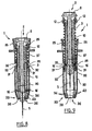
- the syringe 2 has a capacity of 0.5 ml. This comprises a body 3 of X axis and provided at its distal end with a needle holder 4 on which is mounted a needle 5.
- the syringe body 3 has at its proximal end a head or collar 6. The latter has two parallel straight edges 6a, as can be seen on the figure 7 .
- a piston 9 movable inside the syringe body serves to inject the product contained therein, the piston 9 being actuated by a piston rod 7 terminated by a pusher 8 on which the user exerts a thrust to inject the product.
- the needle 5 is initially protected by a cap 19 that the user removes at the time of injection.
- the safety device 1 comprises a sleeve 10 in which the syringe body 3 is engaged.
- the sleeve 10 shown separately on the figure 6 , is constituted, over a major part of its length, of a cylindrical tube of revolution of axis X, with solid wall.
- the sleeve 10 has at its proximal end a flange 11 and two elastically deformable holding tabs 12, diametrically opposed and connected to the flange 11 substantially at the periphery thereof.
- Each leg 12 has, at its upper part, an inclined flank 13 allowing the syringe head 6 to easily cross the tabs 12 and snap into it.
- notch 15 At the rear of each of the flanks 13, is made a notch 15 whose role is explained below.
- the sleeve 10 has at its distal end and on its outer wall two lugs 16 diametrically opposed.
- the diameter of the sleeve 10 and the dimensions of the tabs 12 are chosen so that the sleeve can receive two types of syringes, for example 0.5 ml syringes and 1 ml syringes, the device 1 equipped with a syringe. 1 ml syringe being shown on the figure 10 .
- the sleeve 10 is intended to be introduced into a protective sleeve 20 shown in isolation on the figure 3 .
- This protective sheath 20 comprises, at its proximal portion, a collar 21 on which is connected a generally tubular upper wall 22.
- the collar 21 serves as a bearing surface for the fingers of a user performing the injection.
- the tubular wall 22 comprises two windows 23 each having an upper edge to which is connected a retaining tab 25.
- the latter is adapted to be spaced radially by elastic deformation.
- the lower portion of the windows 23, not occupied by the retaining tabs 25, provides a passage for the retaining tabs 12 of the sleeve 10.
- the retaining tabs 25 each bear on a notch 15 of the retaining tabs 12, thus allowing the sleeve 10 to be retained in the sheath 20.
- the pusher 8 has a sufficient diameter so as to come into contact with the retaining tabs 25 and discard them at the end of the injection.
- the protective sheath 20 comprises, formed on its inner wall, four longitudinal guide ribs arranged in pairs, the ribs 26 and 27 of the same pair forming between them a space allowing the lugs 16 of the sleeve 10 to engage.
- the rib 27 is interrupted so as to form a passage 29. To the right of this rib 27 is formed a stop 30 positioned relative to the passage 29 so that when a lug bears on this stop 30, it is found facing the passage 29 and can engage therein following a rotation of the sleeve 10 relative to the sheath 20.
- the sheath 20 also comprises two elastically deformable locking lugs 31 made in its wall.
- the bent ends 32 are located above the stops 30 so that, during the mounting of the sleeve 10 in the sleeve 20, the lugs 16 do not have to cross the locking tabs 31.
- the protective sheath 20 has, at its distal portion 33, a generally frustoconical shape converging downwards. This part has four slots 34 giving it a certain radial elasticity and thus allowing it to receive the cap 19 or, as we will see hereinafter, another body, of greater diameter than that of the distal opening 36 of the sheath 20.
- the sleeve 20 is, at its distal portion, radially deformable, between a rest configuration, illustrated on the figure 9 , where its opening 36 has a minimum diameter, and a deformed configuration, illustrated in particular on the figure 1 allowing the passage, through the opening 36, of a body having a diameter greater than the minimum diameter of the opening 36.
- this body may be the cap 19 protecting the needle 5 of the syringe 2, as shown in FIG. figure 1 where it can be seen that, before the injection, the cap 19 is mounted in such a way that it protrudes from the sheath 20 through the opening 36.
- the sleeve 20 thus encloses the cap 19, and exerts on it a force which opposes its withdrawal, sufficient to ensure that the cap 19 will not be separated inadvertently from the syringe 2.
- the sleeve 20 and the cap 19 are arranged to prevent, after removal of the cap 19, reintroduction thereof into the sleeve 20 through its opening 36.
- the distal portion of the sheath 20 tightens in such a way that the opening 36 has a diameter smaller than the outside diameter of the cap 19. In this case, the distal portion of the sheath encloses the syringe body 3.
- the opening 36 has a rounded edge 38
- the cap 19 has, at its opening side, a straight edge 39 which abuts against the rounded edge 38 of the opening 36.
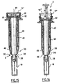
- FIGS. figures 10 and 11 Another body that can be received in the sheath 20 through the opening may be constituted by the syringe body 3, as shown in FIGS. figures 10 and 11 where, as will be seen below, is represented a syringe 2 of greater size (in diameter and length) to the syringe 2 shown on the Figures 1 and 2 .
- the syringe body 3 has a length such that, in the configuration preceding the injection and during the injection, it protrudes from the sheath 20 through the opening 36.
- the sleeve 20 encloses the syringe body 3 which here has a diameter greater than the minimum diameter of the opening 36. This results in a firm hold of the syringe body 3 near the door needle 4
- This maintenance combined with the maintenance of the syringe head 6 provided by the sleeve 10, ensures a rigid holding of the syringe 2 within the sleeve 20, to the benefit of the safety and precision of the injection operations.
- the sleeve 20 may be manufactured by molding.
- the mold employed (not shown) comprises for example a fixed, hollow outer part, within which slides a substantially cylindrical movable part, the mold cavity being formed between the fixed part and the movable part.
- another body that can be received in the sleeve 20 through the opening 36 may be constituted by the movable part of the mold, which, during demolding, is removed from the sleeve 20 in the axial direction, on the side of the opening 36. This removal is facilitated by the radial elasticity of the distal portion 33 of the sheath 20.
- the distal portion 33 of the sheath 20 is pierced with a plurality of slots 34, here four in number, although a different number (at least two, and by example six) can be considered.
- These slots 34 which extend longitudinally and open on the opening 36, define tabs 43 resiliently flexible converging downwards and give the sheath 20 its radial elasticity.
- the sheath 20 further comprises two inner transverse shoulders 35 extending between the guide ribs 26 and 27 of a pair and situated above the curved ends 32 of the locking tabs 31.
- the device 1 comprises a helical spring 37 placed around the sleeve 10 and bearing at one end, against the shoulders 35 and, at the other end, against the collar 11.
- the sleeve 10 is mounted in the sheath 20 in the following manner.
- the sleeve 10 is oriented relative to the sheath 20 so that the two retaining tabs 12 are positioned between the two retaining tabs 25 of the sheath 20.
- the sleeve 10 is introduced into the sleeve 20 while respecting this orientation, this first insertion movement continuing until the lugs 16 of the sleeve 10 bear against the abutments 30 of the sleeve 20.
- the lug 16 is housed between the ribs 26 and 27 and a second insertion movement of the sleeve 10 into the sheath 20 is performed.
- the lugs 16 engaged between the ribs 26 and 27 then ensure the guiding of the sleeve 10 relative to the sheath 20. This movement continues until the retaining lugs 12 snap under the retaining tabs 25.
- the pre-filled syringe 2 is introduced into the sleeve 10, by orienting the syringe head 6 so that the right sides 6a are opposite the retaining tabs 12, as can be seen in FIG. see him on the figure 7 .
- the head 6 snaps onto the retaining tabs 12 so as to be retained on the flange 11.
- one of the ribs is interrupted.
- all the ribs may be continuous and one of the ribs 26 'may be interrupted before the other rib 27', the rib 26 'being shorter than the other.
- a lower passage 29 ' is thus formed below the rib 26', for introducing a lug 16 of the sleeve 10 between the two ribs 26 'and 27' by a rotational movement of a quarter of a turn, according to the arrow F ', of the sleeve 10 with respect to the sheath 10.
- the operation of the safety device 1 is carried out as follows.
- the pusher 8 causes the spacing of the retaining lugs 25 so as to release the sleeve 10 and the spring 37 causes the assembly constituted by the sleeve 10 and syringe 2 to the back, as can be seen on the figure 8 .
- the lugs 16 abut against the shoulders 35 and the needle 5 is set back in the sheath 20.
- the lugs 16 which are engaged above the curved ends 32 of the lugs 31 prevent movement towards the distal end of the sleeve 10 with respect to the sheath 20.
- This safety device 40 is arranged to receive a standard syringe 41. of capacity of 0.5 ml or 1 ml, substantially similar to the syringe 2 described above.
- the safety device 40 comprises a sleeve 42 in which the syringe body 3 is engaged.
- the sleeve 42 has at its proximal end means for holding the flange or head 6 of the syringe body.
- These holding means comprise a flange 45 connected by a plurality of material bridges 47, for example four material bridges 47, to an upper ring 46, the syringe head 6 being retained between the flange 45 and this ring 46.
- the ring 46 defines an upper opening having in axial section a generally frustoconical shape diverging upwardly for guiding the syringe head 6 through this opening during assembly of the syringe in the sleeve 42.
- the sleeve 42 further includes a shoulder 48 defining a sectional enlargement in its proximal portion.
- the sleeve 42 comprises at its distal end a plurality of elastically deformable tabs 51 of reduced thickness, at the end of each of which is formed a lug 50.
- the syringe 2 and the sleeve 42 are immobilized relative to each other.
- the sleeve 42 is intended to be engaged in a protective sheath 60 having in its proximal portion a flange 61 whose lower surface serves as a bearing surface for the fingers of a user during the injection.
- the sleeve 60 has at its proximal end, above the flange 61, a plurality of resiliently deformable retaining tabs 62 folded, at rest, inwardly.
- the retaining tabs 62 in the folded state, bear against the flange 45 of the sleeve 42, thus limiting the upward axial displacement of the assembly constituted by the sleeve 42 and the syringe 2.
- the protective sheath 60 also comprises, substantially at mid-length in the example described, a discontinuous inner surface 65.
- the edge of the surface 65 is generally frustoconical diverging upwards, allowing, when the sleeve 10 is inserted into the the sheath 60, to guide the lugs 50 through this span 65.
- the device 40 comprises non-return or locking means defined by locking tabs 66, substantially similar to the locking tabs 31 previously described and made in the wall of the sleeve 60.
- These locking tabs 66 can be crossed by the lugs 50.
- a helical spring 70 is disposed in the sheath 60, around the sleeve 42, respectively bearing on the bearing surface 65 and the shoulder 48.
- the safety device 40 also comprises a button 71 comprising a cylindrical wall 72 with at its distal end hooks 73 capable of engaging in the aforementioned openings 63 of the sheath 60, located between the tabs 62.
- the cylindrical wall 72 has at its proximal end a flange diverging upwards, on which a user comes to apply his thumb to push the pusher 71.
- the distal edge of the button 71 is intended to come into contact with the tabs 62 and discard them.
- the operation of the security device 40 is carried out as follows.
- the user introduces the needle 5 under the skin of the patient, the syringe being immobilized in translation relative to the sheath 60.
- the user exercises, by means of the index and middle fingers that come resting on the flange 61 and by means of its thumb resting on the head 8, sufficient thrust to inject the product.
- the user At the end of the stroke of the piston rod 7 in the body 3, the user, by means of his thumb which bears on the piston head 8, pushes the button 71 without making any additional gesture other than that producing the piston. injection, so as to spread the tabs 62 and release the sleeve 42.
- the assembly consisting of the syringe 2 and the sleeve 42 can then be driven upwards by the action of the spring 70.
- the needle 5 is then recessed inside the protective sheath 60, thus no longer presenting any danger of contamination and / or injury after injection.
- the lugs 50 engaged above the tabs 66 prevent the syringe from being pushed out of the protective sheath 60, thereby locking the safety device 1 after use.
- the button 71 is constituted by an attached element fixed on the protective sheath 60.
- the safety device comprises a button 71 'made in one piece with the head 8 of the piston rod 7.
- This pusher 71' has at its upper part a concave surface 80 allowing a user to apply his thumb .
- the button 71 has a skirt 81 extending under the surface 80 and allowing, when the piston rod 7 is substantially at the end of the injection stroke, to move the retaining tabs 62 and to release the assembly consisting of the syringe 2 and the sleeve 42.
- the safety device comprises a button 71 "which has a cylindrical wall 72" which is connected to the sleeve 42 by means of elastically deformable arms 83.
- the cylindrical wall 72 ", the elastic arms 83 and the sleeve 42 are made in one piece.
- the pusher 71 "is depressed and the wall 72" causes the spacing of the tabs 62 to release the sleeve 42.
- This feature allows easier introduction of the sleeve 10 during assembly of the device 1.
- This embodiment feature also allows a simplified manufacture of the sheath 20, since it is not necessary to provide an outer mold in two parts whose joint plane would extend between the shoulders 35 and the parts 32 of the lugs 31.
- the molding of the sleeve 20 can be achieved by means of two mold parts, one of which, external, fixed, is in one piece, and the other, inner, movable in translation in the outer part, can be withdrawn towards the proximal portion of the sheath 20 by spreading in its passage the tabs 31.
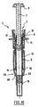
- the tabs 31 may be attached to an upper portion of the sheath 20, situated on the side of its proximal portion ( figure 17 ), as at a lower part of the sheath 20, located on the side of its distal portion 33 ( Figures 18 and 19 ).
Landscapes
- Health & Medical Sciences (AREA)
- Engineering & Computer Science (AREA)
- Heart & Thoracic Surgery (AREA)
- Vascular Medicine (AREA)
- Anesthesiology (AREA)
- Biomedical Technology (AREA)
- Environmental & Geological Engineering (AREA)
- Hematology (AREA)
- Life Sciences & Earth Sciences (AREA)
- Animal Behavior & Ethology (AREA)
- General Health & Medical Sciences (AREA)
- Public Health (AREA)
- Veterinary Medicine (AREA)
- Infusion, Injection, And Reservoir Apparatuses (AREA)
Claims (14)
- Sicherheitsvorrichtung (1) für eine Spritze (2) mit Nadel (5), die eine Hülse (10) zum Aufnehmen des Körpers (3) der Spritze (2) aufweist und eine Schutzhülle (20), in der die Spritze (2) gleiten kann, und Mittel, um die Spritze (2) und die Hülse in der Hülle (20) gleiten zu lassen zwischen einer ersten Position, die die Injektion ermöglicht, und einer zweiten Position, in der die Nadel (5) der Spritze (2) ins Innere der Hülle (20) zurückgezogen ist, wobei die Hülle (20) an einem distalen Teil (33), der in radialer Richtung elastisch verformbar ist, eine Öffnung (36) aufweist, um zu ermöglichen, dass die Nadel (5) der Spritze (2) aus der Hülle (20) herausragt, dadurch gekennzeichnet, dass die Hülle (20), an ihrem distalen Teil (33), in radialer Richtung elastisch verformbar ist, zwischen einer Ruhestellung, in der ihre Öffnung (36) einen minimalen Durchmesser aufweist, und einer verformten Stellung, die, durch die Öffnung (36) hindurch, einen Körper (3, 19) mit einem Durchmesser passieren lässt, der größer ist als der minimale Durchmesser der Öffnung (36).
- Vorrichtung nach Anspruch 1, dadurch gekennzeichnet, dass der Körper (19) eine Kappe ist, dazu bestimmt, die Nadel (5) der Spritze (2) zu schützen.
- Vorrichtung nach Anspruch 1, dadurch gekennzeichnet, dass der Körper (3) der Körper der Spritze (2) ist.
- Vorrichtung nach Anspruch 1, dadurch gekennzeichnet, dass der Körper, wobei die Hülle durch Formung ausgebildet ist, ein beweglicher Teil einer Form ist.
- Vorrichtung nach einem der Ansprüche 1 bis 4, dadurch gekennzeichnet, dass die Hülle (20), an ihrem distalen Teil (33), kegelstumpfförmig ist.
- Vorrichtung nach einem der Ansprüche 1 bis 5, dadurch gekennzeichnet, dass der distale Teil (33) der Hülle (20) gespalten ist.
- Vorrichtung nach Anspruch 6, dadurch gekennzeichnet, dass der distale Teil (33) der Hülle (20) mehrere Längsspalte (34) aufweist, welche konvergente elastische Zungen (43) festlegen.
- Vorrichtung nach einem der vorstehenden Ansprüche, dadurch gekennzeichnet, dass die Hülse (10) an ihrem proximalen Teil Mittel zum Halten des Kopfteils (6) der Spritze (2) aufweist, die sich eignen, um Spritzen zumindest zweier verschiedener Typen zu halten.
- Vorrichtung nach Anspruch 8, dadurch gekennzeichnet, dass die Haltemittel angeordnet sind, um den Halt eines das Kopfteil der Spritze (2) bildenden Kragens (6) zu gewährleisten.
- Vorrichtung nach einem der vorstehenden Ansprüche, dadurch gekennzeichnet, dass sie ein elastisches Element (37) aufweist, das zwischen der Hülle (20) und der aus der Hülse (10) und der Spritze (2) bestehenden Anordnung wirkt, und das es ermöglicht, die Anordnung, am Ende der Injektion, von der ersten Position in die zweite zu überführen durch eine relative Zurückbewegung dieser Anordnung in Bezug auf die Hülle (20).
- Anordnung, die eine Spritze (2) und eine die Spritze (2) ausstattende Sicherheitsvorrichtung (1) aufweist, dadurch gekennzeichnet, dass die Sicherheitsvorrichtung (1) einem der Ansprüche 1 bis 10 entspricht.
- Anordnung nach Anspruch 11, dadurch gekennzeichnet, dass sie weiterhin eine Kappe (19) aufweist, die die Nadel (5) der Spritze (2) schützt.
- Anordnung nach Anspruch 12, dadurch gekennzeichnet, dass die Kappe (19) so angebracht ist, dass sie aus der Hülle (20) durch die distale Öffnung (36) derselben herausragt.
- Anordnung nach Anspruch 13, dadurch gekennzeichnet, dass die Hülle (20) und die Kappe (19) so angeordnet sind, dass sie, nach Herausziehen der Kappe (19), die erneute Einführung derselben durch die Öffnung (36) der Hülle (20) verhindern.
Applications Claiming Priority (3)
| Application Number | Priority Date | Filing Date | Title |
|---|---|---|---|
| FR0113256 | 2001-10-15 | ||
| FR0113256A FR2830765B1 (fr) | 2001-10-15 | 2001-10-15 | Dispositif de securite pour une seringue |
| PCT/FR2002/003529 WO2003033059A1 (fr) | 2001-10-15 | 2002-10-15 | Dispositif de securite pour une seringue |
Publications (2)
| Publication Number | Publication Date |
|---|---|
| EP1436026A1 EP1436026A1 (de) | 2004-07-14 |
| EP1436026B1 true EP1436026B1 (de) | 2010-12-15 |
Family
ID=8868291
Family Applications (1)
| Application Number | Title | Priority Date | Filing Date |
|---|---|---|---|
| EP02790515A Expired - Lifetime EP1436026B1 (de) | 2001-10-15 | 2002-10-15 | Sicherheitsvorrichtung für eine spritze |
Country Status (6)
| Country | Link |
|---|---|
| US (1) | US8337467B2 (de) |
| EP (1) | EP1436026B1 (de) |
| AT (1) | ATE491487T1 (de) |
| DE (1) | DE60238629D1 (de) |
| FR (1) | FR2830765B1 (de) |
| WO (1) | WO2003033059A1 (de) |
Families Citing this family (103)
| Publication number | Priority date | Publication date | Assignee | Title |
|---|---|---|---|---|
| US6776777B2 (en) | 2002-05-10 | 2004-08-17 | Becton, Dickinson And Company | Passive safety shield system for injection devices |
| DE10261575A1 (de) * | 2002-12-23 | 2004-07-08 | Nova Lung Gmbh | Vorrichtung zur Kanülierung eines Blut führenden Gefäßes und deren Verwendung zur Kanülierung von Blut führenden Gefäßen |
| FR2852851B1 (fr) | 2003-03-25 | 2006-01-06 | Sedat | Dispositif de protection d'aiguille destine a une seringue, et dispositif d'injection comprenant une seringue et ce dispositif de protection |
| FR2860162B1 (fr) * | 2003-09-26 | 2006-06-02 | Becton Dickinson France | Dispositif de protection d'un appareil d'injection |
| FR2861310B1 (fr) | 2003-10-22 | 2006-09-22 | Plastef Investissements | Dispositif de seringue d'injection securise |
| FR2861598B1 (fr) * | 2003-10-29 | 2006-06-16 | Plastef Investissements | Dispositif d'injection securise pour une seringue |
| US7497847B2 (en) | 2003-11-03 | 2009-03-03 | Becton, Dickinson And Company | Safety shield system for a syringe |
| US7468054B2 (en) | 2003-11-03 | 2008-12-23 | Becton, Dickinson And Company | Safety shield system for a syringe |
| US7101351B2 (en) | 2003-11-03 | 2006-09-05 | Becton, Dickinson And Company | Safety device for a syringe |
| US7604613B2 (en) | 2004-01-20 | 2009-10-20 | Beckton, Dickinson And Company | Syringe having a retractable needle |
| US7344517B2 (en) | 2004-01-20 | 2008-03-18 | Becton, Dickinson And Company | Syringe having a retractable needle |
| WO2005089831A1 (en) * | 2004-03-16 | 2005-09-29 | Glenord Pty Ltd | Single use retractable syringe |
| GB2414406B (en) * | 2004-05-28 | 2009-03-18 | Cilag Ag Int | Injection device |
| GB2414402B (en) | 2004-05-28 | 2009-04-22 | Cilag Ag Int | Injection device |
| GB2414409B (en) * | 2004-05-28 | 2009-11-18 | Cilag Ag Int | Injection device |
| GB2414399B (en) * | 2004-05-28 | 2008-12-31 | Cilag Ag Int | Injection device |
| GB2414403B (en) | 2004-05-28 | 2009-01-07 | Cilag Ag Int | Injection device |
| GB2414401B (en) | 2004-05-28 | 2009-06-17 | Cilag Ag Int | Injection device |
| GB2414775B (en) | 2004-05-28 | 2008-05-21 | Cilag Ag Int | Releasable coupling and injection device |
| GB2414400B (en) | 2004-05-28 | 2009-01-14 | Cilag Ag Int | Injection device |
| FR2871705B1 (fr) * | 2004-06-18 | 2006-09-15 | Mb Innovation Sarl | Dispositif a usage unique d'injection d'un fluide medicamenteux |
| GB0414054D0 (en) | 2004-06-23 | 2004-07-28 | Owen Mumford Ltd | Improvements relating to automatic injection devices |
| ITMI20041471A1 (it) * | 2004-07-21 | 2004-10-21 | Sergio Restelli | Kit di sicurezza per siringa standard relativa a siringa monouso di sicurezza |
| US8062252B2 (en) | 2005-02-18 | 2011-11-22 | Becton, Dickinson And Company | Safety shield system for a syringe |
| GB2427826B (en) | 2005-04-06 | 2010-08-25 | Cilag Ag Int | Injection device comprising a locking mechanism associated with integrally formed biasing means |
| GB2425062B (en) * | 2005-04-06 | 2010-07-21 | Cilag Ag Int | Injection device |
| GB2424836B (en) | 2005-04-06 | 2010-09-22 | Cilag Ag Int | Injection device (bayonet cap removal) |
| GB2424835B (en) * | 2005-04-06 | 2010-06-09 | Cilag Ag Int | Injection device (modified trigger) |
| GB2424837B (en) * | 2005-04-06 | 2010-10-06 | Cilag Ag Int | Injection device |
| GB2424838B (en) * | 2005-04-06 | 2011-02-23 | Cilag Ag Int | Injection device (adaptable drive) |
| DE602005018480D1 (de) | 2005-08-30 | 2010-02-04 | Cilag Gmbh Int | Nadelvorrichtung für eine vorgefüllte Spritze |
| US20110098656A1 (en) | 2005-09-27 | 2011-04-28 | Burnell Rosie L | Auto-injection device with needle protecting cap having outer and inner sleeves |
| GB2438593B (en) | 2006-06-01 | 2011-03-30 | Cilag Gmbh Int | Injection device (cap removal feature) |
| GB2438591B (en) | 2006-06-01 | 2011-07-13 | Cilag Gmbh Int | Injection device |
| GB2438590B (en) | 2006-06-01 | 2011-02-09 | Cilag Gmbh Int | Injection device |
| TWI498137B (zh) | 2006-06-30 | 2015-09-01 | Abbvie Biotechnology Ltd | 自動注射裝置 |
| US10420880B2 (en) * | 2007-10-02 | 2019-09-24 | West Pharma. Services IL, Ltd. | Key for securing components of a drug delivery system during assembly and/or transport and methods of using same |
| US9656019B2 (en) | 2007-10-02 | 2017-05-23 | Medimop Medical Projects Ltd. | Apparatuses for securing components of a drug delivery system during transport and methods of using same |
| US9173997B2 (en) | 2007-10-02 | 2015-11-03 | Medimop Medical Projects Ltd. | External drug pump |
| FR2922112B1 (fr) | 2007-10-11 | 2009-12-04 | Rexam Pharma La Verpilliere | Dispositif de securite pour une seringue d'injection de liquide et ensemble a seringue comprenant ce dispositif |
| FR2922455B1 (fr) | 2007-10-23 | 2010-10-29 | Plastef Investissements | Dispositif de seringue comprenant un corps de seringue et un manchon de support. |
| GB0724944D0 (en) * | 2007-12-20 | 2008-01-30 | Ucb Pharma Sa | Auto injector |
| FR2932096B1 (fr) | 2008-06-06 | 2012-03-16 | Rexam Pharma La Verpilliere | Dispositif de securite pour un dispositif d'injection |
| GB2461086B (en) | 2008-06-19 | 2012-12-05 | Cilag Gmbh Int | Injection device |
| GB2461089B (en) | 2008-06-19 | 2012-09-19 | Cilag Gmbh Int | Injection device |
| GB2461087B (en) | 2008-06-19 | 2012-09-26 | Cilag Gmbh Int | Injection device |
| GB2461088B (en) * | 2008-06-19 | 2012-09-26 | Cilag Gmbh Int | Injection device |
| GB2461084B (en) | 2008-06-19 | 2012-09-26 | Cilag Gmbh Int | Fluid transfer assembly |
| GB2461085B (en) | 2008-06-19 | 2012-08-29 | Cilag Gmbh Int | Injection device |
| GB0815748D0 (en) * | 2008-08-29 | 2008-10-08 | Liversidge Barry P | Medical needle assembly |
| MX2011011541A (es) | 2009-04-29 | 2012-02-28 | Abbott Biotech Ltd | Dispositivo de inyeccion automatico. |
| TWI519330B (zh) * | 2009-06-02 | 2016-02-01 | 賽諾菲阿凡提斯德意志有限公司 | 使用者可選擇式之醫療模組 |
| US8758301B2 (en) * | 2009-12-15 | 2014-06-24 | Abbvie Biotechnology Ltd | Firing button for automatic injection device |
| GB2478349A (en) * | 2010-03-05 | 2011-09-07 | Owen Mumford Ltd | Injection device having projections reducing the diameter of the syringe passage |
| KR101850687B1 (ko) | 2010-04-21 | 2018-04-20 | 애브비 바이오테크놀로지 리미티드 | 치료제의 제어된 전달을 위한 착용형 자동 주사 디바이스 |
| FR2959419B1 (fr) | 2010-04-28 | 2013-06-28 | Rexam Healthcare La Verpillier | Dispositif de securite pour seringue d'injection pre-remplie |
| FR2961403B1 (fr) | 2010-06-17 | 2013-06-14 | Rexam Healthcare La Verpillier | Ensemble d'une seringue et d'un dispositif de securite |
| MX2013000070A (es) * | 2010-07-02 | 2013-02-15 | Sanofi Aventis Deutschland | Proyector de aguja para un dispositivo de seguridad, dispositivo de seguridad y dispositivo de inyeccion. |
| MX388000B (es) | 2011-01-24 | 2025-03-19 | Abbvie Biotechnology Ltd | Separación de protectores de aguja de jeringas y dispositivos de inyección automáticos. |
| RU2602039C2 (ru) | 2011-01-24 | 2016-11-10 | Эббви Байотекнолоджи Лтд. | Автоматические инъекционные устройства, имеющие наформованные поверхности захвата |
| MX336571B (es) | 2011-01-24 | 2016-01-25 | Elcam Medical Agricultural Cooperative Ass Ltd | Inyector. |
| FR2971424B1 (fr) * | 2011-02-14 | 2013-11-29 | Marc Brunel | Seringue de securite |
| WO2012138318A1 (en) | 2011-04-04 | 2012-10-11 | West Pharmaceutical Services, Inc. | Needle safety shield |
| EP2601992A1 (de) | 2011-12-08 | 2013-06-12 | Sanofi-Aventis Deutschland GmbH | Spritzenträger |
| US9867940B2 (en) * | 2011-12-15 | 2018-01-16 | Shl Group Ab | Auto-injection device |
| EP2623145A1 (de) * | 2012-02-03 | 2013-08-07 | Q Stat Pty Ltd | Einfahrbare Nadelvorrichtung und -verfahren |
| US9248242B2 (en) * | 2012-04-20 | 2016-02-02 | Safety Syringes, Inc. | Anti-needle stick safety device for injection device |
| US9050416B2 (en) | 2012-11-01 | 2015-06-09 | Tech Group Europe Limited | Needle Safety device with floating ring |
| EP2752211A1 (de) * | 2013-01-07 | 2014-07-09 | F. Hoffmann-La Roche Ltd. | Sicherheitsvorrichtung für eine Injektionsspritze |
| EP2777684A1 (de) | 2013-03-14 | 2014-09-17 | Sanofi-Aventis Deutschland GmbH | Medikamentenbehälterträger und -adapter |
| GB2517896B (en) | 2013-06-11 | 2015-07-08 | Cilag Gmbh Int | Injection device |
| GB2515039B (en) | 2013-06-11 | 2015-05-27 | Cilag Gmbh Int | Injection Device |
| GB2515032A (en) | 2013-06-11 | 2014-12-17 | Cilag Gmbh Int | Guide for an injection device |
| GB2515038A (en) | 2013-06-11 | 2014-12-17 | Cilag Gmbh Int | Injection device |
| FR3011186B1 (fr) | 2013-09-30 | 2017-12-08 | Rexam Healthcare La Verpillier | Dispositif de reception pour une seringue d'injection comprenant un capuchon de protection de l'aiguille |
| SE539276C2 (sv) * | 2013-10-30 | 2017-06-13 | Danderyds Snickeri Ab | Förfarande och anordning för att öka säkerheten vid borttagande av en kanyl från en spruta |
| FR3025724B1 (fr) * | 2014-09-17 | 2016-11-04 | Nemera La Verpilliere | Dispositif de securite pour une seringue d'injection comprenant des moyens de retrecissement de l'ouverture du fourreau perfectionnes |
| USD765838S1 (en) | 2015-03-26 | 2016-09-06 | Tech Group Europe Limited | Syringe retention clip |
| US10149943B2 (en) | 2015-05-29 | 2018-12-11 | West Pharma. Services IL, Ltd. | Linear rotation stabilizer for a telescoping syringe stopper driverdriving assembly |
| TW201705994A (zh) | 2015-06-03 | 2017-02-16 | 賽諾菲阿凡提斯德意志有限公司 | 自動注射器及組裝方法 |
| TW201700117A (zh) | 2015-06-03 | 2017-01-01 | 賽諾菲阿凡提斯德意志有限公司 | 用於自動注射器的注射筒托架和組裝方法 |
| US9987432B2 (en) | 2015-09-22 | 2018-06-05 | West Pharma. Services IL, Ltd. | Rotation resistant friction adapter for plunger driver of drug delivery device |
| US10576207B2 (en) | 2015-10-09 | 2020-03-03 | West Pharma. Services IL, Ltd. | Angled syringe patch injector |
| JP7017512B2 (ja) | 2015-10-09 | 2022-02-08 | ウェスト ファーマ サービシーズ イスラエル リミテッド | 充填済流体容器の屈曲流体路型付属物 |
| US11311674B2 (en) | 2016-01-21 | 2022-04-26 | West Pharma. Services IL, Ltd. | Medicament delivery device comprising a visual indicator |
| EP3711793B1 (de) | 2016-01-21 | 2021-12-01 | West Pharma Services IL, Ltd. | Verfahren zur verbindung einer patrone mit einem automatischen injektor |
| JP6542481B2 (ja) | 2016-01-21 | 2019-07-10 | ウェスト ファーマ サービシーズ イスラエル リミテッド | システム |
| US11389597B2 (en) | 2016-03-16 | 2022-07-19 | West Pharma. Services IL, Ltd. | Staged telescopic screw assembly having different visual indicators |
| KR101707884B1 (ko) * | 2016-05-10 | 2017-02-17 | (주)에프에이 | 주사기용 주사액 이물질 여과장치 |
| EP3978047B1 (de) | 2016-08-01 | 2023-08-23 | West Pharma Services IL, Ltd | Feder zur verhinderung von teilweisem türverschluss |
| EP3490643B1 (de) | 2016-08-01 | 2021-10-27 | West Pharma. Services Il, Ltd. | Verdrehsicherungsstift |
| GB201706697D0 (en) | 2017-04-27 | 2017-06-14 | Ucb Biopharma Sprl | Cap for an injector |
| WO2018206488A1 (en) * | 2017-05-09 | 2018-11-15 | Novo Nordisk A/S | Injection device incorporating a needle safety arrangement |
| GB2563027B (en) | 2017-05-30 | 2022-04-06 | Janssen Pharmaceuticals Inc | Grip accessory for a manual injection device |
| EP3630226B1 (de) | 2017-05-30 | 2025-10-22 | West Pharma. Services Il, Ltd. | Modularer antriebsstrang für am körper tragbaren injektor |
| GB2563029B (en) | 2017-05-30 | 2022-06-08 | Janssen Pharmaceuticals Inc | Grip accessory for a manual injection device |
| JP1691364S (de) | 2019-11-01 | 2021-08-02 | ||
| US11850410B2 (en) * | 2020-03-05 | 2023-12-26 | Dali Medical Devices Ltd | Automatically retracting safety needle assembly |
| US12005244B2 (en) | 2020-03-27 | 2024-06-11 | Medivena Sp. Z O.O. | Needle-based device based on direct wing-based coupling of a needle shield to a barrel thereof and safety mechanism implemented therein |
| FR3136175B1 (fr) | 2022-06-06 | 2025-11-14 | Nemera La Verpilliere | Dispositif médical, système d’administration de médicament et procédé de fabrication associés |
| USD1108627S1 (en) | 2023-10-02 | 2026-01-06 | Regeneron Pharmaceuticals, Inc. | Drug-delivery device |
| USD1109322S1 (en) | 2023-10-02 | 2026-01-13 | Regeneron Pharmaceuticals, Inc. | Drug-delivery device |
| CN117771475B (zh) * | 2024-02-27 | 2024-05-10 | 山东永聚医药科技股份有限公司 | 固体制剂用植入式预灌封注射器及其制备方法 |
Family Cites Families (31)
| Publication number | Priority date | Publication date | Assignee | Title |
|---|---|---|---|---|
| US3667465A (en) * | 1969-12-08 | 1972-06-06 | Kimberly Clark Co | Applicator tubes for suppositories and the like |
| US4220151A (en) * | 1978-09-20 | 1980-09-02 | Sherwood Medical Industries Inc. | Disposable Luer lock syringe |
| US4927416A (en) * | 1987-12-02 | 1990-05-22 | National Medical Device Corporation | User-protective hypodermic syringe holder |
| US4863434A (en) * | 1988-01-29 | 1989-09-05 | Bayless William B | Automatic needle sheath for disposable syringe |
| US4850977A (en) * | 1988-01-29 | 1989-07-25 | Bayless William B | Button activated automatic needle sheath for disposable syringe |
| US5437647A (en) * | 1990-05-09 | 1995-08-01 | Safety Syringes, Inc. | Disposable self-shielding aspirating syringe |
| ES2082052T3 (es) * | 1990-07-19 | 1996-03-16 | Nardino Righi | Jeringuilla de seguridad, de un solo uso. |
| IT1253104B (it) * | 1991-07-02 | 1995-07-10 | Paolo Romagnoli | Siringa monouso |
| US5197953A (en) * | 1991-07-08 | 1993-03-30 | John Colonna | Cap assembly |
| US5167640A (en) * | 1991-07-31 | 1992-12-01 | Balding James G | Syringe needle shield |
| US5176656A (en) * | 1991-08-12 | 1993-01-05 | Bayless William B | Automatically positioned needle sheath for a disposable hypodermic syringe |
| US5492536A (en) * | 1992-01-21 | 1996-02-20 | Mascia; Michael F. | Safely disposable syringe |
| EP0768902B1 (de) * | 1992-11-19 | 1998-07-15 | Tebro S.A. | Automatische injektionsvorrichtung für vorgefüllte spritzen |
| US5342320A (en) * | 1993-01-15 | 1994-08-30 | Cameron Robert W | Hypodermic syringe having shielding to prevent accidental injury following use |
| US5478316A (en) * | 1994-02-02 | 1995-12-26 | Becton, Dickinson And Company | Automatic self-injection device |
| EP0680767A1 (de) * | 1994-05-06 | 1995-11-08 | Nardino Righi | Einwegspritze |
| FR2733687B1 (fr) * | 1995-05-04 | 1997-10-03 | Brunel Marc | Procede de fabrication d'un dispositif d'injection du type pre-rempli renfermant une dose de liquide a injecter, et dispositif d'injection realise |
| US5562626A (en) * | 1995-09-11 | 1996-10-08 | Sanpietro; Joseph A. | Safety syringe |
| IT1304761B1 (it) * | 1998-01-20 | 2001-03-29 | Nardino Righi | Siringa monouso di sicurezza. |
| US6319233B1 (en) | 1998-04-17 | 2001-11-20 | Becton, Dickinson And Company | Safety shield system for prefilled syringes |
| US6361525B2 (en) * | 1998-07-29 | 2002-03-26 | Becton Dickinson And Company | Single-use syringe |
| FR2787335B1 (fr) | 1998-12-08 | 2001-02-16 | Roger Denis | Securite pour seringues pre-remplies |
| FR2788986B3 (fr) | 1999-01-28 | 2001-01-19 | Dit De Callac Jean Marie Colin | Dispositif de securite automatique autobloquant, universel, en une piece pour seringue verre pre-remplies |
| FR2799376B1 (fr) | 1999-10-07 | 2002-01-18 | Marc Brunel | Dispositif d'injection a usage unique |
| FR2801795B1 (fr) * | 1999-12-07 | 2002-07-05 | Plastef Investissements | Dispositif de support de securite pour une seringue et ensemble d'un tel dispositif et d'une seringue |
| GB0003790D0 (en) * | 2000-02-18 | 2000-04-05 | Astrazeneca Uk Ltd | Medical device |
| US6391004B1 (en) * | 2000-07-21 | 2002-05-21 | Retrax Safety Systems, Inc. | Fluid collector assembly |
| TW475449U (en) * | 2001-05-22 | 2002-02-01 | Chiou Jiu Chuen | Rotation sleeve control type pull-back safe injector |
| FR2837107B1 (fr) * | 2002-03-18 | 2005-02-25 | Sedat | Dispositif de protection d'aiguille destine a une seringue, et dispositif d'injection comprenant une seringue et ce dispositif de protection |
| US20060189931A1 (en) * | 2003-03-24 | 2006-08-24 | John Riemelmoser | Syringe with retractable needle |
| FR2852851B1 (fr) * | 2003-03-25 | 2006-01-06 | Sedat | Dispositif de protection d'aiguille destine a une seringue, et dispositif d'injection comprenant une seringue et ce dispositif de protection |
-
2001
- 2001-10-15 FR FR0113256A patent/FR2830765B1/fr not_active Expired - Lifetime
-
2002
- 2002-10-15 WO PCT/FR2002/003529 patent/WO2003033059A1/fr not_active Ceased
- 2002-10-15 US US10/492,625 patent/US8337467B2/en not_active Expired - Fee Related
- 2002-10-15 EP EP02790515A patent/EP1436026B1/de not_active Expired - Lifetime
- 2002-10-15 DE DE60238629T patent/DE60238629D1/de not_active Expired - Lifetime
- 2002-10-15 AT AT02790515T patent/ATE491487T1/de not_active IP Right Cessation
Also Published As
| Publication number | Publication date |
|---|---|
| FR2830765A1 (fr) | 2003-04-18 |
| FR2830765B1 (fr) | 2004-07-23 |
| EP1436026A1 (de) | 2004-07-14 |
| US20060036216A1 (en) | 2006-02-16 |
| WO2003033059A1 (fr) | 2003-04-24 |
| US8337467B2 (en) | 2012-12-25 |
| ATE491487T1 (de) | 2011-01-15 |
| DE60238629D1 (de) | 2011-01-27 |
Similar Documents
| Publication | Publication Date | Title |
|---|---|---|
| FR2830765A1 (fr) | Dispositif de securite pour une seringue | |
| EP1485153B1 (de) | Nadelschutzvorrichtung für eine spritze sowie injektionsvorrichtung bestehend aus einer spritze und dieser schutzvorrichtung | |
| EP1224000B1 (de) | Sicherheitsvorrichtung für injektionsspritzen | |
| EP1827565B1 (de) | Implantierbare rückinjektionsvorrichtung | |
| EP1682207B1 (de) | Geschützte injektionsspritzenvorrichtung | |
| EP1079877B1 (de) | Injektionsspritze mit einem federbeaufschlagten nadelschutz | |
| EP1605997B1 (de) | Nadelschutzvorrichtung für eine spritze, und injektionsvorrichtung mit einer spritze und dieser nadelschutzvorrichtung | |
| EP1330279B1 (de) | Injektionsspritze mit einem verschiebbaren nadelschutz | |
| FR2884721A1 (fr) | Ensemble d'injection et dispositif d'assistance a l'injection | |
| EP1532997B1 (de) | Nadelschutzvorrichtung für eine Karpulle | |
| EP1436027B1 (de) | Sicherheitsvorrichtung für eine spritze | |
| WO2015044561A1 (fr) | Dispositif de réception pour une seringue d'injection comprenant un capuchon de protection de l'aiguille | |
| FR2774294A1 (fr) | Dispositif d'injection automatique d'une dose de produit medicamenteux | |
| EP1235603A2 (de) | Sicherheitsvorrichtung für eine spritze | |
| CA2361100A1 (fr) | Ensemble de securite pour une seringue pre-remplie d'injection de liquide, notamment d'un medicament | |
| FR2930161A1 (fr) | Ensemble de protection d'aiguille comportant un element de verrouillage mobile radialement. | |
| EP1224001B1 (de) | Hypodermatische wegwerfspritze mit arretierbarer schutzhülse | |
| BE654563A (de) | ||
| CH333737A (fr) | Seringue hypodermique | |
| WO2010012876A2 (fr) | Dispositif sécurisé d'injection à usage unique | |
| EP1368081B1 (de) | Spritze | |
| FR2846244A1 (fr) | Dispositif de protection de l'aiguille d'un catheter |
Legal Events
| Date | Code | Title | Description |
|---|---|---|---|
| PUAI | Public reference made under article 153(3) epc to a published international application that has entered the european phase |
Free format text: ORIGINAL CODE: 0009012 |
|
| 17P | Request for examination filed |
Effective date: 20040414 |
|
| AK | Designated contracting states |
Kind code of ref document: A1 Designated state(s): AT BE BG CH CY CZ DE DK EE ES FI FR GB GR IE IT LI LU MC NL PT SE SK TR |
|
| AX | Request for extension of the european patent |
Extension state: AL LT LV MK RO SI |
|
| RAP1 | Party data changed (applicant data changed or rights of an application transferred) |
Owner name: REXAM PHARMA LA VERPILLIERE |
|
| 17Q | First examination report despatched |
Effective date: 20050726 |
|
| GRAP | Despatch of communication of intention to grant a patent |
Free format text: ORIGINAL CODE: EPIDOSNIGR1 |
|
| RAP1 | Party data changed (applicant data changed or rights of an application transferred) |
Owner name: REXAM HEALTHCARE LA VERPILLIERE |
|
| GRAS | Grant fee paid |
Free format text: ORIGINAL CODE: EPIDOSNIGR3 |
|
| GRAA | (expected) grant |
Free format text: ORIGINAL CODE: 0009210 |
|
| AK | Designated contracting states |
Kind code of ref document: B1 Designated state(s): AT BE BG CH CY CZ DE DK EE ES FI FR GB GR IE IT LI LU MC NL PT SE SK TR |
|
| REG | Reference to a national code |
Ref country code: CH Ref legal event code: EP Ref country code: GB Ref legal event code: FG4D Free format text: NOT ENGLISH |
|
| REG | Reference to a national code |
Ref country code: IE Ref legal event code: FG4D |
|
| REF | Corresponds to: |
Ref document number: 60238629 Country of ref document: DE Date of ref document: 20110127 Kind code of ref document: P |
|
| REG | Reference to a national code |
Ref country code: NL Ref legal event code: VDEP Effective date: 20101215 |
|
| PG25 | Lapsed in a contracting state [announced via postgrant information from national office to epo] |
Ref country code: FI Free format text: LAPSE BECAUSE OF FAILURE TO SUBMIT A TRANSLATION OF THE DESCRIPTION OR TO PAY THE FEE WITHIN THE PRESCRIBED TIME-LIMIT Effective date: 20101215 Ref country code: NL Free format text: LAPSE BECAUSE OF FAILURE TO SUBMIT A TRANSLATION OF THE DESCRIPTION OR TO PAY THE FEE WITHIN THE PRESCRIBED TIME-LIMIT Effective date: 20101215 Ref country code: BG Free format text: LAPSE BECAUSE OF FAILURE TO SUBMIT A TRANSLATION OF THE DESCRIPTION OR TO PAY THE FEE WITHIN THE PRESCRIBED TIME-LIMIT Effective date: 20110315 Ref country code: CY Free format text: LAPSE BECAUSE OF FAILURE TO SUBMIT A TRANSLATION OF THE DESCRIPTION OR TO PAY THE FEE WITHIN THE PRESCRIBED TIME-LIMIT Effective date: 20101215 Ref country code: AT Free format text: LAPSE BECAUSE OF FAILURE TO SUBMIT A TRANSLATION OF THE DESCRIPTION OR TO PAY THE FEE WITHIN THE PRESCRIBED TIME-LIMIT Effective date: 20101215 Ref country code: SE Free format text: LAPSE BECAUSE OF FAILURE TO SUBMIT A TRANSLATION OF THE DESCRIPTION OR TO PAY THE FEE WITHIN THE PRESCRIBED TIME-LIMIT Effective date: 20101215 |
|
| REG | Reference to a national code |
Ref country code: IE Ref legal event code: FD4D |
|
| PG25 | Lapsed in a contracting state [announced via postgrant information from national office to epo] |
Ref country code: GR Free format text: LAPSE BECAUSE OF FAILURE TO SUBMIT A TRANSLATION OF THE DESCRIPTION OR TO PAY THE FEE WITHIN THE PRESCRIBED TIME-LIMIT Effective date: 20110316 Ref country code: ES Free format text: LAPSE BECAUSE OF FAILURE TO SUBMIT A TRANSLATION OF THE DESCRIPTION OR TO PAY THE FEE WITHIN THE PRESCRIBED TIME-LIMIT Effective date: 20110326 Ref country code: PT Free format text: LAPSE BECAUSE OF FAILURE TO SUBMIT A TRANSLATION OF THE DESCRIPTION OR TO PAY THE FEE WITHIN THE PRESCRIBED TIME-LIMIT Effective date: 20110415 Ref country code: EE Free format text: LAPSE BECAUSE OF FAILURE TO SUBMIT A TRANSLATION OF THE DESCRIPTION OR TO PAY THE FEE WITHIN THE PRESCRIBED TIME-LIMIT Effective date: 20101215 Ref country code: CZ Free format text: LAPSE BECAUSE OF FAILURE TO SUBMIT A TRANSLATION OF THE DESCRIPTION OR TO PAY THE FEE WITHIN THE PRESCRIBED TIME-LIMIT Effective date: 20101215 Ref country code: IE Free format text: LAPSE BECAUSE OF FAILURE TO SUBMIT A TRANSLATION OF THE DESCRIPTION OR TO PAY THE FEE WITHIN THE PRESCRIBED TIME-LIMIT Effective date: 20101215 |
|
| PG25 | Lapsed in a contracting state [announced via postgrant information from national office to epo] |
Ref country code: SK Free format text: LAPSE BECAUSE OF FAILURE TO SUBMIT A TRANSLATION OF THE DESCRIPTION OR TO PAY THE FEE WITHIN THE PRESCRIBED TIME-LIMIT Effective date: 20101215 |
|
| PLBE | No opposition filed within time limit |
Free format text: ORIGINAL CODE: 0009261 |
|
| STAA | Information on the status of an ep patent application or granted ep patent |
Free format text: STATUS: NO OPPOSITION FILED WITHIN TIME LIMIT |
|
| PG25 | Lapsed in a contracting state [announced via postgrant information from national office to epo] |
Ref country code: DK Free format text: LAPSE BECAUSE OF FAILURE TO SUBMIT A TRANSLATION OF THE DESCRIPTION OR TO PAY THE FEE WITHIN THE PRESCRIBED TIME-LIMIT Effective date: 20101215 |
|
| 26N | No opposition filed |
Effective date: 20110916 |
|
| PG25 | Lapsed in a contracting state [announced via postgrant information from national office to epo] |
Ref country code: IT Free format text: LAPSE BECAUSE OF FAILURE TO SUBMIT A TRANSLATION OF THE DESCRIPTION OR TO PAY THE FEE WITHIN THE PRESCRIBED TIME-LIMIT Effective date: 20101215 |
|
| REG | Reference to a national code |
Ref country code: DE Ref legal event code: R097 Ref document number: 60238629 Country of ref document: DE Effective date: 20110916 |
|
| BERE | Be: lapsed |
Owner name: REXAM HEALTHCARE LA VERPILLIERE Effective date: 20111031 |
|
| PG25 | Lapsed in a contracting state [announced via postgrant information from national office to epo] |
Ref country code: MC Free format text: LAPSE BECAUSE OF NON-PAYMENT OF DUE FEES Effective date: 20111031 |
|
| REG | Reference to a national code |
Ref country code: CH Ref legal event code: PL |
|
| PG25 | Lapsed in a contracting state [announced via postgrant information from national office to epo] |
Ref country code: LI Free format text: LAPSE BECAUSE OF NON-PAYMENT OF DUE FEES Effective date: 20111031 Ref country code: CH Free format text: LAPSE BECAUSE OF NON-PAYMENT OF DUE FEES Effective date: 20111031 Ref country code: BE Free format text: LAPSE BECAUSE OF NON-PAYMENT OF DUE FEES Effective date: 20111031 |
|
| PG25 | Lapsed in a contracting state [announced via postgrant information from national office to epo] |
Ref country code: LU Free format text: LAPSE BECAUSE OF NON-PAYMENT OF DUE FEES Effective date: 20111015 |
|
| PG25 | Lapsed in a contracting state [announced via postgrant information from national office to epo] |
Ref country code: TR Free format text: LAPSE BECAUSE OF FAILURE TO SUBMIT A TRANSLATION OF THE DESCRIPTION OR TO PAY THE FEE WITHIN THE PRESCRIBED TIME-LIMIT Effective date: 20101215 |
|
| REG | Reference to a national code |
Ref country code: FR Ref legal event code: CD Owner name: NEMERA LA VERPILLERIE, FR Effective date: 20140731 |
|
| REG | Reference to a national code |
Ref country code: FR Ref legal event code: PLFP Year of fee payment: 14 |
|
| REG | Reference to a national code |
Ref country code: FR Ref legal event code: PLFP Year of fee payment: 15 |
|
| REG | Reference to a national code |
Ref country code: DE Ref legal event code: R082 Ref document number: 60238629 Country of ref document: DE Representative=s name: MAIWALD PATENTANWALTS- UND RECHTSANWALTSGESELL, DE Ref country code: DE Ref legal event code: R082 Ref document number: 60238629 Country of ref document: DE Representative=s name: GRUENECKER PATENT- UND RECHTSANWAELTE PARTG MB, DE |
|
| REG | Reference to a national code |
Ref country code: FR Ref legal event code: PLFP Year of fee payment: 16 |
|
| REG | Reference to a national code |
Ref country code: FR Ref legal event code: RM Effective date: 20170927 |
|
| REG | Reference to a national code |
Ref country code: FR Ref legal event code: PLFP Year of fee payment: 17 |
|
| REG | Reference to a national code |
Ref country code: DE Ref legal event code: R082 Ref document number: 60238629 Country of ref document: DE Representative=s name: MAIWALD PATENTANWALTS- UND RECHTSANWALTSGESELL, DE Ref country code: DE Ref legal event code: R081 Ref document number: 60238629 Country of ref document: DE Owner name: NEMERA LA VERPILLIERE, FR Free format text: FORMER OWNER: REXAM HEALTHCARE LA VERPILLIERE, LA VERPILLIERE, FR |
|
| PGFP | Annual fee paid to national office [announced via postgrant information from national office to epo] |
Ref country code: GB Payment date: 20211022 Year of fee payment: 20 Ref country code: DE Payment date: 20211020 Year of fee payment: 20 |
|
| PGFP | Annual fee paid to national office [announced via postgrant information from national office to epo] |
Ref country code: FR Payment date: 20211028 Year of fee payment: 20 |
|
| REG | Reference to a national code |
Ref country code: DE Ref legal event code: R071 Ref document number: 60238629 Country of ref document: DE |
|
| REG | Reference to a national code |
Ref country code: GB Ref legal event code: PE20 Expiry date: 20221014 |
|
| PG25 | Lapsed in a contracting state [announced via postgrant information from national office to epo] |
Ref country code: GB Free format text: LAPSE BECAUSE OF EXPIRATION OF PROTECTION Effective date: 20221014 |