EP1607139A2 - Vorrichtung und Verfahren für das Beschichten von Tabletten mittels einer rotierenden Trommel - Google Patents
Vorrichtung und Verfahren für das Beschichten von Tabletten mittels einer rotierenden Trommel Download PDFInfo
- Publication number
- EP1607139A2 EP1607139A2 EP04102777A EP04102777A EP1607139A2 EP 1607139 A2 EP1607139 A2 EP 1607139A2 EP 04102777 A EP04102777 A EP 04102777A EP 04102777 A EP04102777 A EP 04102777A EP 1607139 A2 EP1607139 A2 EP 1607139A2
- Authority
- EP
- European Patent Office
- Prior art keywords
- drum
- air
- suspension
- supply
- tablets
- Prior art date
- Legal status (The legal status is an assumption and is not a legal conclusion. Google has not performed a legal analysis and makes no representation as to the accuracy of the status listed.)
- Granted
Links
Images

Classifications
-
- B—PERFORMING OPERATIONS; TRANSPORTING
- B05—SPRAYING OR ATOMISING IN GENERAL; APPLYING FLUENT MATERIALS TO SURFACES, IN GENERAL
- B05B—SPRAYING APPARATUS; ATOMISING APPARATUS; NOZZLES
- B05B13/00—Machines or plants for applying liquids or other fluent materials to surfaces of objects or other work by spraying, not covered by groups B05B1/00 - B05B11/00
- B05B13/02—Means for supporting work; Arrangement or mounting of spray heads; Adaptation or arrangement of means for feeding work
- B05B13/0221—Means for supporting work; Arrangement or mounting of spray heads; Adaptation or arrangement of means for feeding work characterised by the means for moving or conveying the objects or other work, e.g. conveyor belts
- B05B13/025—Means for supporting work; Arrangement or mounting of spray heads; Adaptation or arrangement of means for feeding work characterised by the means for moving or conveying the objects or other work, e.g. conveyor belts the objects or work being present in bulk
- B05B13/0257—Means for supporting work; Arrangement or mounting of spray heads; Adaptation or arrangement of means for feeding work characterised by the means for moving or conveying the objects or other work, e.g. conveyor belts the objects or work being present in bulk in a moving container, e.g. a rotatable foraminous drum
-
- B—PERFORMING OPERATIONS; TRANSPORTING
- B01—PHYSICAL OR CHEMICAL PROCESSES OR APPARATUS IN GENERAL
- B01J—CHEMICAL OR PHYSICAL PROCESSES, e.g. CATALYSIS OR COLLOID CHEMISTRY; THEIR RELEVANT APPARATUS
- B01J2/00—Processes or devices for granulating materials, e.g. fertilisers in general; Rendering particulate materials free flowing in general, e.g. making them hydrophobic
- B01J2/006—Coating of the granules without description of the process or the device by which the granules are obtained
-
- B—PERFORMING OPERATIONS; TRANSPORTING
- B01—PHYSICAL OR CHEMICAL PROCESSES OR APPARATUS IN GENERAL
- B01J—CHEMICAL OR PHYSICAL PROCESSES, e.g. CATALYSIS OR COLLOID CHEMISTRY; THEIR RELEVANT APPARATUS
- B01J2/00—Processes or devices for granulating materials, e.g. fertilisers in general; Rendering particulate materials free flowing in general, e.g. making them hydrophobic
- B01J2/12—Processes or devices for granulating materials, e.g. fertilisers in general; Rendering particulate materials free flowing in general, e.g. making them hydrophobic in rotating drums
Definitions
- the invention relates to a device and a method for coating of tablets.
- a device for coating tablets can be purchased The drum is perforated Segments on, The drum is stored horizontally, This can be around a horizontal axis are rotated, the drum has a discharge opening and a door open, through the door, the tablets in the Put the drum into it, in the drum the tablets are coated. Through the discharge opening, the coated tablets emptied
- the door is attached laterally or on one end of the drum. These This page is referred to as the front side, the discharge opening may be located in the circumference of the drum, is the discharge opening below, so can through this opening due to gravity the coated tablets are removed.
- Seen from the front is about a first feeder to coating material, which is to be coated, introduced into the drum.
- Air is supplied to the interior of the drum via a second supply fed.
- Aqueous or organic solvent suspensions or paints are placed over the first supply line in the interior of the Brought mixing vessel.
- the suspension occurs over at least a nozzle out, the nozzle is designed so that the suspension inside the drum is fogged.
- the suspension gets so misty on the tablets, while the mixing vessel is slowly around the horizontal Axis rotated, Typically, the drum rotates with up to 25 Revolutions per minute,
- the air flow occurs through the perforation of the drift ice segments out.
- the perforation is in the prior art in one embodiment distributed over the circumference of the drum, It is equal to four big segments.
- the nozzle is directed downwards.
- the suspension occurs immediately in the direction of the mix from the first supply line, the air flow occurs in the same direction, the perforated plate is so according to this Purpose,
- the object of the invention is to simplify the coating of tablets
- the suspension in contrast to the prescribed state of Technology now fed the suspension laterally over a first side of the drum and the air laterally on the opposite side.
- the suspension thus, for example, on the front and the air over the Fed back. This ensures that on the side of the from the operation is done by the user, more space exists, This place is for the user of the machine in the production of special Interest. Production processes can be simplified in this way improve and / or cheapen. Also, the design effort is lower. So u, a. Cost advantages in the production.
- the suspension is fed from the front.
- the feeder as well as the nozzle, over which suspension is supplied, must from time to Time to be cleaned, It is therefore beneficial to this feed of the Front, so provide from the operator side. This is the result Cleaning effort less.
- the air supply falls namely a corresponding Cleaning effort not or in a much lower Scope. Therefore, the air supply preferably takes place from the comparatively hard to reach back.
- the suspension supplied below or at the level of the axis of rotation of the drum the air is supplied wholly or predominantly above the axis of rotation of the drum, It can be directed so the air coming from above in the direction of bulk material while keeping the aerosolized suspension in the direction of Mix or transport the tablets.
- Air and suspension then occur in the same direction from the respective supply means, the exit direction of air and suspension then close with the vertical an angle greater than 0 ° and less than 90 °, regular this angle is between 10 ° and 60 °, in particular at 25 to 50 ° usual revolutions of up to 25 revolutions per minute.
- the air was through an annular recess fed to the front of the drum.
- the inventive Drum has at the front still advantageous this annular Recess out.
- one circular plate provided, which is rotatable with the remaining part of Drum is connected.
- the rotatable connection is preferably sealing designed.
- the drum rotates and not the circular plate.
- the air is over a corresponding line passed, the technical area, so For example, electronic controls, motors, etc., the overall device is then placed behind the back of the drum.
- This technical area is separated from the production area, what for The trouble-free operation is beneficial, therefore, in the rear area advantageously not also an annular opening as in the front provided so as to provide the desired shielding of the production area from the technical field.
- the sealing connection in rotatable mounting is generally from an elastomer or an elastomeric blend, it is advantageous food safe and usually depending on the application suitable for pharmaceutical purposes, silicone is a typical material, which is well suited for the aforementioned purposes,
- a drum in which only individual segments of the circumference are perforated (partially perforated drum). It is further provided a drum, the perforated over the entire circumference of the drum (fully perforated drum), The side walls of the two drums are for shielding purposes excluded from the perforation, Both drums are like that adapted to the rest of the device that, depending on Need the respective drum to be used in the overall device can, with one and the same periphery so different Drums are used, this is beneficial to different To be able to produce medicines in a case with the partial perforated drum and in the other case with the fully perforated Drum have been validated.
- a fully perforated drum also from the inside provided with an air supply or, an air supply shoe has been successful, it succeeds in comparison to the prior art, the required Clearly reduce air volume, compared to the state of the art with the fully perforated drums, this results in cost advantages in the Coating of tablets.
- a typical diameter of a drum according to the invention is 25 cm to 1.70 m, The width or depth of the drum is typically 30 cm to 1.50 m.
- the useful volume of the drum is typically included 1 to 1000 l.
- a useful volume is the volume required for recording the tablets is suitable. This useful volume is sufficient, for example, in the case the drum with an annular opening up to this opening.
- the air supply at the border has the function of a barrier for the To form suspension. It can so no sucked suspension in the Enter interior of the device, this reduces cleaning costs because the interior is correspondingly less polluted.
- the drum is in an airtight sealed Box, This box is designed to protect the environment escaping dust caused by dried suspensions and tablet dust has been formed,
- Ring On the front there is an encircling in one embodiment Ring, The encircling ring runs on rollers while the drum is rotated In this way, the drum is stored at the front, The ring is sealed to the outside via a seal. The final one Part is hermetically sealed to the outside, so as to production to shield to the outside.
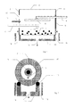
- FIG. 1 shows schematically a device according to the invention for the Coating Tablets 1,
- the device includes one with perforations 2 provided drum having a front 3 and a back 4 having.
- the drum is shown in section in FIG. 1,
- a first feed 5 for suspension takes place via the front side 3 of FIG Drum.
- a second supply 6 for air via the back 4 of Drum The supply of suspension is at the bottom inside the Drum provided with at least one nozzle 7. Through the nozzle 7 enters the Suspension in the direction of the in-drum tablets 1 nebulized out.
- the supply of air at the end points inside the drum a perforated plate 8 through which the supplied air exits, Flow of air is due to the perforated plate 8, which consists of a Sheet metal may consist (perforated plate), as well as a suitably selected flow rate rectified, the nozzle 7 for the supply of Suspension and the end with the perforated plate 8 for the supply of air is inside the drum down, that is equal to the nozzle directed to the product bed, so that the escaping suspension as possible completely passed to the tablets 1.
- the supply of air into the interior of the drum is effected by a rotatably mounted circular plate 9, the part of the back 4 of the Drum is,
- the circular plate is provided with a hole over which enters the supply or, line 6 in the interior of the drum.
- Rotatable with this circular plate 9 is the remaining rear area 4 of the drum connected, neither this remaining back area 4 nor the circular plate 9 are perforated to the back and To shield also the product-side space, the drum becomes with the exception of the circular ring during the coating of the Turned tablets 1.
- Devices of the device such as means for heating air, blower for transporting air and / or suspension, Drive means for rotating the drum, electric and electronic Control devices for the control of the device and / or electrical Closing and other actuating means are wholly or at least mostly seen from the inside of the drum behind the back 4 placed. On the one hand, this area is due to the closed Shielded back.
- the facilities are so well protected and can also be easily shielded electrically, also remains the in front of the back 4 lying area, which serves the production, then free or at least largely free of facilities that would otherwise be the Handling of the device by a human operator disadvantageous would disturb.
- the front side has a circular opening 10 through which the feeder 5 for the suspension reaches the inside of the drum,
- the entire circumference of the drum can be perforated without leaving known in the prior art disadvantages in terms of increased air supply to have to accept.
- a suction device 12 is provided below the drum.
- the suction device comprises a housing which is rotatably mounted with two Rolls 13 is provided, as shown in Figure 2, On the rollers 13, the drum is stored or placed, the rollers 13 serve at the same time as a seal.
- the rollers be turned motorized.
- the motorized rotation of the drum can made so easy, since then omitted any other storage In this case it is possible to connect the supply lines 5 or 6 along the Rotary axis to lead into the interior of the drum. So can in the case of air supply the circular plate accounts for what the manufacturing cost can lower. Otherwise, the annular opening 10 can be omitted, what reduces the design effort and increases the useful volume.
- the sealing of the suction device protects the production room Impurities due to dried out of the drum Suspension,
- the sealing can be done by taking appropriate measures Sealing lips, sealing strips or sealing rolls take place,
- the suction device 1 2 has at its border air supply 14th These limits preferably to the front 3 and to the back 4 the drum. It forms so air curtain adjacent to the front 3 and on the back 4, The air curtain shield the production room in front of dried suspension, so from dust down through the perforation out of the drum.
- the embodiment according to FIG. 2 does not yet take into account that suspension and air supply advantageously directed obliquely downwards are to be taken into account so that during operation the Tablets are located centrally next to the lowest point in the drum namely laterally in the direction of rotation of the drum,
- the suction device in the air and suspension at an angle towards the product bed flow, is preferred accordingly arranged obliquely, as the figure 3 can be seen, then serve the Rollers 13 only for support.
- a seal can contribute to these roles this embodiment in principle not to cause, since then in usually at least one roller 13 is located outside the suction device, The rollers under the drum are then only for support, but not the seal,
- the seal of the suction device can be easily with a sealing lip 15 sealed.
- the sealing lip 15 then seals towards the inner side from, as shown in the figure 1, there is then a free air outlet to the drum outside,
- a simple seal can Also, two sealing lips adjacent to the drum, as indicated in Figure 3 becomes,
- the perforated plate 8, the nozzle, the normal of the product bed surface 1 7 and the outlet channel of the suction 16 are preferably located on a common, obliquely extending axis (indicated in Fig. 3).
Landscapes
- Chemical & Material Sciences (AREA)
- Organic Chemistry (AREA)
- Chemical Kinetics & Catalysis (AREA)
- Medical Preparation Storing Or Oral Administration Devices (AREA)
- Medicinal Preparation (AREA)
- Spray Control Apparatus (AREA)
- Formation And Processing Of Food Products (AREA)
Abstract
Description
Claims (15)
- Vorrichtung für das Beschichten von Tabletten (1) mit einer mit Perforierungen (2) versehenen Trommel, die eine Vorderseite (3) und eine Rückseite (4) aufweist, dadurch gekennzeichnet, dass eine erste Zuführung (5) für Suspension oder Luft über die Vorderseite (3) vorgesehen ist und eine zweite Zuführung (6) für Luft oder Suspension durch die Rückseite (4) vorgesehen ist.
- Vorrichtung nach Anspruch 1 , bei der die Zuführung (5) für die Suspension über die Vorderseite (3) erfolgt.
- Vorrichtung nach Anspruch 1 oder 2, bei der die Zuführung von Suspension am Ende im Inneren der Trommel mit mindestens einer Düse (7) versehen ist.
- Vorrichtung nach einem der vorhergehenden Ansprüche, bei der die Zuführung für Luft am Ende im Inneren der Trommel mit einem Lochblech oder einer gelochten Platte (8) versehen ist.
- Vorrichtung nach einem der vorhergehenden Ansprüche, bei der das Ende (7) der Zuführung von Suspension und/ oder das Ende (8) der Zuführung von Luft im Inneren der Trommel nach unten und zwar insbesondere schräg nach unten gerichtet ist, so dass die Strömungsrichtung der Luft und der Suspension mit der Vertikalen einen Winkel zwischen 0° und 45° einschließen und dabei Luft und Suspension in gleicher Richtung strömen,
- Vorrichtung nach einem der vorhergehenden Ansprüche, bei der das Ende (8) der Zuführung von Luft im Inneren der Trommel ganz oder überwiegend oberhalb des Endes (7) der Zuführung von Suspension angeordnet ist.
- Vorrichtung nach einem der vorhergehenden Ansprüche, bei der die Zuführung (6) von Luft in das Innere der Trommel durch eine drehfest angebrachte kreisförmige Platte (9) erfolgt, die bevorzugt Teil der Rückseite (4) der Trommel ist.
- Vorrichtung nach einem der vorhergehenden Ansprüche, bei der elektrische Einrichtungen der Vorrichtung von der Trommel aus gesehen hinter der Rückseite (4) platziert sind,
- Vorrichtung nach einem der vorhergehenden Ansprüche, bei der der gesamte Umfang der Trommel perforiert ist.
- Vorrichtung nach einem der vorhergehenden Ansprüche, bei der unterhalb der Trommel eine Absaugeinrichtung (12) vorgesehen ist,
- Vorrichtung nach dem vorhergehenden Anspruch, bei der die Absaugvorrichtung mit drehbar gelagerten Rollen (13) versehen ist, auf denen die Trommel abgelegt ist.
- Vorrichtung nach einem der beiden vorhergehenden Ansprüche, bei der die Absaugeinrichtung bei ihrer Umrandung eine Luftzuführung (14) aufweist und zwar insbesondere angrenzend an die Vorderseite (3) der Trommel und an die Rückseite (4) der Trommel,
- Trommel für eine Vorrichtung nach einem der vorhergehenden Ansprüche mit einer ring- oder kreisförmigen Öffnung (10) an einer Seite und einer drehbar mit der übrigen Trommel verbundenen kreisförmigen Scheibe (9) an der gegenüberliegenden Seite, wobei die kreisförmige Scheibe (9) mit einer Bohrung versehen ist.
- Absaugeinrichtung (1 2) mit einem der Absaugung dienendem Gehäuse für eine Vorrichtung nach einem der vorhergehenden Ansprüche, die seitlich neben dem der Absaugung dienendem Gehäuse Luftzuführungen aufweist,
- Verfahren für das Beschichten von Tabletten mit den Schritten:Befüllen einer Trommel mit Tabletten,Zuführung von Suspension in das Innere der Trommel über eine Leitung, die durch die eine Seite der Trommel geführt ist;Vernebelung der Suspension im Inneren der Trommel;Erwärmung und Zuführung von Luft in das Innere der Trommel über eine andere Leitung, die durch die andere Seite der Trommel geführt ist;Drehen der Trommel während der Zuführung von Luft und Suspension;Entnahme der dadurch beschichteten Tabletten aus der Trommel.
Priority Applications (9)
| Application Number | Priority Date | Filing Date | Title |
|---|---|---|---|
| DE502004008912T DE502004008912D1 (de) | 2004-06-17 | 2004-06-17 | Vorrichtung und Verfahren für das Beschichten von Tabletten mittels einer rotierenden Trommel |
| EP04102777A EP1607139B1 (de) | 2004-06-17 | 2004-06-17 | Vorrichtung und Verfahren für das Beschichten von Tabletten mittels einer rotierenden Trommel |
| ES04102777T ES2321294T3 (es) | 2004-06-17 | 2004-06-17 | Dispositivo y procedimiento para el recubrimiento de tabletas. |
| AT04102777T ATE421386T1 (de) | 2004-06-17 | 2004-06-17 | Vorrichtung und verfahren für das beschichten von tabletten mittels einer rotierenden trommel |
| CNA2005800193643A CN1968760A (zh) | 2004-06-17 | 2005-03-02 | 采用一个旋转滚筒对药片进行包覆的装置和方法 |
| US11/628,785 US20080050518A1 (en) | 2004-06-17 | 2005-03-02 | Device and Method for Coating Tablets by Means of One Rotatable Drum |
| RU2006143569/11A RU2359895C2 (ru) | 2004-06-17 | 2005-03-02 | Устройство и способ нанесения покрытий на таблетки с помощью вращающегося барабана |
| PCT/EP2005/050915 WO2005123267A1 (de) | 2004-06-17 | 2005-03-02 | Vorrichtung und verfahren für das beschichten von tabletten mittels einer rotierenden trommel |
| JP2007515910A JP2008502466A (ja) | 2004-06-17 | 2005-03-02 | 回転ドラムによる錠剤のコーティング装置および方法 |
Applications Claiming Priority (1)
| Application Number | Priority Date | Filing Date | Title |
|---|---|---|---|
| EP04102777A EP1607139B1 (de) | 2004-06-17 | 2004-06-17 | Vorrichtung und Verfahren für das Beschichten von Tabletten mittels einer rotierenden Trommel |
Publications (3)
| Publication Number | Publication Date |
|---|---|
| EP1607139A2 true EP1607139A2 (de) | 2005-12-21 |
| EP1607139A3 EP1607139A3 (de) | 2006-10-04 |
| EP1607139B1 EP1607139B1 (de) | 2009-01-21 |
Family
ID=34929211
Family Applications (1)
| Application Number | Title | Priority Date | Filing Date |
|---|---|---|---|
| EP04102777A Expired - Lifetime EP1607139B1 (de) | 2004-06-17 | 2004-06-17 | Vorrichtung und Verfahren für das Beschichten von Tabletten mittels einer rotierenden Trommel |
Country Status (9)
| Country | Link |
|---|---|
| US (1) | US20080050518A1 (de) |
| EP (1) | EP1607139B1 (de) |
| JP (1) | JP2008502466A (de) |
| CN (1) | CN1968760A (de) |
| AT (1) | ATE421386T1 (de) |
| DE (1) | DE502004008912D1 (de) |
| ES (1) | ES2321294T3 (de) |
| RU (1) | RU2359895C2 (de) |
| WO (1) | WO2005123267A1 (de) |
Cited By (1)
| Publication number | Priority date | Publication date | Assignee | Title |
|---|---|---|---|---|
| CN110652455A (zh) * | 2019-10-23 | 2020-01-07 | 安徽金牛药械股份有限公司 | 一种熬制及制备膏药的装置 |
Families Citing this family (2)
| Publication number | Priority date | Publication date | Assignee | Title |
|---|---|---|---|---|
| DE102005010005A1 (de) * | 2005-03-04 | 2006-12-28 | Nunner, Dieter | Vorrichtung und Verfahren zur Beschichtung von Kleinteilen |
| DE102008001104A1 (de) | 2008-04-10 | 2009-10-15 | Gebrüder Lödige Maschinenbau GmbH | Geschlossen vollperforierte Coating Trommel |
Family Cites Families (16)
| Publication number | Priority date | Publication date | Assignee | Title |
|---|---|---|---|---|
| SU367900A1 (ru) * | 1971-04-13 | 1973-01-26 | Устройство для нанесения защитных покрытий | |
| SU738682A1 (ru) * | 1978-01-06 | 1980-06-05 | Ленинградский технологический институт холодильной промышленности | Устройство дл непрерывного нанесени покрытий на гранулированные продукты |
| DE3130166C1 (de) * | 1981-07-30 | 1982-11-11 | Herbert 7853 Steinen Hüttlin | Dragiertrommel |
| CH656077A5 (de) * | 1982-01-29 | 1986-06-13 | Glatt Maschinen & Apparatebau | Verfahren zum ueberziehen von teilchen, insbesondere arzneimittel-teilchen, und vorrichtung zur durchfuehrung des verfahrens. |
| JPH0763608B2 (ja) * | 1986-09-02 | 1995-07-12 | フロイント産業株式会社 | 粉粒体処理装置 |
| DE4036668C2 (de) * | 1990-11-17 | 1997-09-11 | Driam Metallprodukt Gmbh & Co | Beschichtungsmaschie mit Gegenstrom- und Gleichstrom-Luftführung |
| DE4138997A1 (de) * | 1991-11-27 | 1993-06-03 | Lorenz B Dipl Ing Bohle | Vorrichtung zum dragieren von stueckigen produkten, insbesondere pillen und tabletten |
| JP3327476B2 (ja) * | 1992-08-12 | 2002-09-24 | 株式会社パウレック | 造粒コーティング装置 |
| JP3349580B2 (ja) * | 1994-03-03 | 2002-11-25 | フロイント産業株式会社 | パンコーティング装置 |
| DE4446468A1 (de) * | 1994-12-23 | 1996-06-27 | Basf Ag | Verfahren zur Herstellung von umhüllten Tabletten |
| FR2769524B1 (fr) * | 1998-01-06 | 1999-12-31 | Ethypharm Lab Prod Ethiques | Dispositif d'enrobage pour granules a absorber par voie orale |
| JP2000140709A (ja) * | 1998-09-08 | 2000-05-23 | Freunt Ind Co Ltd | コーティング装置 |
| JP4037974B2 (ja) * | 1998-12-22 | 2008-01-23 | フロイント産業株式会社 | コーティング装置およびコーティング方法 |
| JP2002066298A (ja) * | 2000-09-01 | 2002-03-05 | Freunt Ind Co Ltd | 回転ドラム型造粒コーティング装置および回転ドラム型造粒コーティング方法 |
| AU2002253882A1 (en) * | 2001-01-30 | 2002-08-28 | The Procter And Gamble Company | Coating compositions for modifying surfaces |
| JP4009464B2 (ja) * | 2002-01-31 | 2007-11-14 | 株式会社パウレック | コーティング装置 |
-
2004
- 2004-06-17 AT AT04102777T patent/ATE421386T1/de not_active IP Right Cessation
- 2004-06-17 DE DE502004008912T patent/DE502004008912D1/de not_active Expired - Lifetime
- 2004-06-17 ES ES04102777T patent/ES2321294T3/es not_active Expired - Lifetime
- 2004-06-17 EP EP04102777A patent/EP1607139B1/de not_active Expired - Lifetime
-
2005
- 2005-03-02 JP JP2007515910A patent/JP2008502466A/ja active Pending
- 2005-03-02 CN CNA2005800193643A patent/CN1968760A/zh active Pending
- 2005-03-02 US US11/628,785 patent/US20080050518A1/en not_active Abandoned
- 2005-03-02 WO PCT/EP2005/050915 patent/WO2005123267A1/de not_active Ceased
- 2005-03-02 RU RU2006143569/11A patent/RU2359895C2/ru not_active IP Right Cessation
Cited By (1)
| Publication number | Priority date | Publication date | Assignee | Title |
|---|---|---|---|---|
| CN110652455A (zh) * | 2019-10-23 | 2020-01-07 | 安徽金牛药械股份有限公司 | 一种熬制及制备膏药的装置 |
Also Published As
| Publication number | Publication date |
|---|---|
| CN1968760A (zh) | 2007-05-23 |
| EP1607139A3 (de) | 2006-10-04 |
| ES2321294T3 (es) | 2009-06-04 |
| RU2006143569A (ru) | 2008-07-27 |
| EP1607139B1 (de) | 2009-01-21 |
| RU2359895C2 (ru) | 2009-06-27 |
| DE502004008912D1 (de) | 2009-03-12 |
| US20080050518A1 (en) | 2008-02-28 |
| JP2008502466A (ja) | 2008-01-31 |
| WO2005123267A1 (de) | 2005-12-29 |
| ATE421386T1 (de) | 2009-02-15 |
Similar Documents
| Publication | Publication Date | Title |
|---|---|---|
| DE3328820C2 (de) | ||
| EP0085650B1 (de) | Vorrichtung zum Überziehen von Teilchen, insbesondere Arzneimittel-Teilchen | |
| DE102007005250B3 (de) | Verfahren zum kontinuierlichen Trockenmahlbetrieb einer Turmreibmühle und Turmreibmühle | |
| DE69609012T2 (de) | Vertikale Getreide-Poliermaschine | |
| WO2018210657A1 (de) | Siebkugelmühle zur aufbereitung von metallhaltigem grobmaterial | |
| DE2506005C3 (de) | Austragvorrichtung für einen Schüttgutbunker | |
| DE1268784B (de) | Verfahren und Vorrichtung zum Aufbringen einer UEberzugsschicht auf insbesondere pharmazeutische Tabletten | |
| DE4440875A1 (de) | Vorrichtung zur Herstellung von Pastillen | |
| DE3030017C2 (de) | Millvorrichtung für Leder | |
| DE10008742C2 (de) | Aufsatz für Aktenvernichter zur Aufnahme und Zuführung von Schriftgut | |
| EP0101701B1 (de) | Vorrichtung zum überziehen eines dragiergutes | |
| DE2259450A1 (de) | Vorrichtung zum ablegen von koernigem saatgut im erdreich, vorzugsweise in verbindung mit einzelkornsaemaschinen | |
| DE19948727A1 (de) | Kreislaufmahleinrichtung mit Hochdruck-Walzenmühle und Sichter | |
| DE3140624A1 (en) | Dried material pulverizing and discharging device for multistage continuous vacuum drying apparatus | |
| EP1607139B1 (de) | Vorrichtung und Verfahren für das Beschichten von Tabletten mittels einer rotierenden Trommel | |
| DE2363921A1 (de) | Tablettenpresse, insbesondere rundlauf-tablettenpresse | |
| EP2613893B1 (de) | Behälterreinigungssystem und behälterreinigungsverfahren | |
| DE3626903C2 (de) | Vorrichtung zur Herstellung von Kompost | |
| DE60005972T2 (de) | Verfahren und vorrichtung zum verdichten von pulverförmigem material | |
| EP2608685A1 (de) | Vorrichtung zum behandeln von tabak | |
| DE602005001429T2 (de) | Schleuderradanlage | |
| DE4120456A1 (de) | Verfahren sowohl zum zerkleinern als auch zum trennen von materialien | |
| DE102008001104A1 (de) | Geschlossen vollperforierte Coating Trommel | |
| DE2846313A1 (de) | Tierfuetterungsvorrichtung | |
| EP4323119B1 (de) | Verdichte- und zerkleinerungseinrichtung |
Legal Events
| Date | Code | Title | Description |
|---|---|---|---|
| PUAI | Public reference made under article 153(3) epc to a published international application that has entered the european phase |
Free format text: ORIGINAL CODE: 0009012 |
|
| AK | Designated contracting states |
Kind code of ref document: A2 Designated state(s): AT BE BG CH CY CZ DE DK EE ES FI FR GB GR HU IE IT LI LU MC NL PL PT RO SE SI SK TR |
|
| AX | Request for extension of the european patent |
Extension state: AL HR LT LV MK |
|
| PUAL | Search report despatched |
Free format text: ORIGINAL CODE: 0009013 |
|
| AK | Designated contracting states |
Kind code of ref document: A3 Designated state(s): AT BE BG CH CY CZ DE DK EE ES FI FR GB GR HU IE IT LI LU MC NL PL PT RO SE SI SK TR |
|
| AX | Request for extension of the european patent |
Extension state: AL HR LT LV MK |
|
| 17P | Request for examination filed |
Effective date: 20060918 |
|
| AKX | Designation fees paid |
Designated state(s): AT BE BG CH CY CZ DE DK EE ES FI FR GB GR HU IE IT LI LU MC NL PL PT RO SE SI SK TR |
|
| 17Q | First examination report despatched |
Effective date: 20080407 |
|
| GRAP | Despatch of communication of intention to grant a patent |
Free format text: ORIGINAL CODE: EPIDOSNIGR1 |
|
| GRAS | Grant fee paid |
Free format text: ORIGINAL CODE: EPIDOSNIGR3 |
|
| GRAA | (expected) grant |
Free format text: ORIGINAL CODE: 0009210 |
|
| AK | Designated contracting states |
Kind code of ref document: B1 Designated state(s): AT BE BG CH CY CZ DE DK EE ES FI FR GB GR HU IE IT LI LU MC NL PL PT RO SE SI SK TR |
|
| REG | Reference to a national code |
Ref country code: GB Ref legal event code: FG4D Free format text: NOT ENGLISH |
|
| REG | Reference to a national code |
Ref country code: CH Ref legal event code: NV Representative=s name: BOVARD AG PATENTANWAELTE Ref country code: CH Ref legal event code: EP |
|
| REG | Reference to a national code |
Ref country code: IE Ref legal event code: FG4D Free format text: LANGUAGE OF EP DOCUMENT: GERMAN |
|
| REF | Corresponds to: |
Ref document number: 502004008912 Country of ref document: DE Date of ref document: 20090312 Kind code of ref document: P |
|
| REG | Reference to a national code |
Ref country code: ES Ref legal event code: FG2A Ref document number: 2321294 Country of ref document: ES Kind code of ref document: T3 |
|
| PG25 | Lapsed in a contracting state [announced via postgrant information from national office to epo] |
Ref country code: FI Free format text: LAPSE BECAUSE OF FAILURE TO SUBMIT A TRANSLATION OF THE DESCRIPTION OR TO PAY THE FEE WITHIN THE PRESCRIBED TIME-LIMIT Effective date: 20090121 Ref country code: SI Free format text: LAPSE BECAUSE OF FAILURE TO SUBMIT A TRANSLATION OF THE DESCRIPTION OR TO PAY THE FEE WITHIN THE PRESCRIBED TIME-LIMIT Effective date: 20090121 |
|
| REG | Reference to a national code |
Ref country code: IE Ref legal event code: FD4D |
|
| PG25 | Lapsed in a contracting state [announced via postgrant information from national office to epo] |
Ref country code: SE Free format text: LAPSE BECAUSE OF FAILURE TO SUBMIT A TRANSLATION OF THE DESCRIPTION OR TO PAY THE FEE WITHIN THE PRESCRIBED TIME-LIMIT Effective date: 20090421 Ref country code: PT Free format text: LAPSE BECAUSE OF FAILURE TO SUBMIT A TRANSLATION OF THE DESCRIPTION OR TO PAY THE FEE WITHIN THE PRESCRIBED TIME-LIMIT Effective date: 20090622 Ref country code: PL Free format text: LAPSE BECAUSE OF FAILURE TO SUBMIT A TRANSLATION OF THE DESCRIPTION OR TO PAY THE FEE WITHIN THE PRESCRIBED TIME-LIMIT Effective date: 20090121 |
|
| PG25 | Lapsed in a contracting state [announced via postgrant information from national office to epo] |
Ref country code: IE Free format text: LAPSE BECAUSE OF FAILURE TO SUBMIT A TRANSLATION OF THE DESCRIPTION OR TO PAY THE FEE WITHIN THE PRESCRIBED TIME-LIMIT Effective date: 20090121 Ref country code: EE Free format text: LAPSE BECAUSE OF FAILURE TO SUBMIT A TRANSLATION OF THE DESCRIPTION OR TO PAY THE FEE WITHIN THE PRESCRIBED TIME-LIMIT Effective date: 20090121 Ref country code: DK Free format text: LAPSE BECAUSE OF FAILURE TO SUBMIT A TRANSLATION OF THE DESCRIPTION OR TO PAY THE FEE WITHIN THE PRESCRIBED TIME-LIMIT Effective date: 20090121 Ref country code: CZ Free format text: LAPSE BECAUSE OF FAILURE TO SUBMIT A TRANSLATION OF THE DESCRIPTION OR TO PAY THE FEE WITHIN THE PRESCRIBED TIME-LIMIT Effective date: 20090121 |
|
| PLBE | No opposition filed within time limit |
Free format text: ORIGINAL CODE: 0009261 |
|
| STAA | Information on the status of an ep patent application or granted ep patent |
Free format text: STATUS: NO OPPOSITION FILED WITHIN TIME LIMIT |
|
| PG25 | Lapsed in a contracting state [announced via postgrant information from national office to epo] |
Ref country code: SK Free format text: LAPSE BECAUSE OF FAILURE TO SUBMIT A TRANSLATION OF THE DESCRIPTION OR TO PAY THE FEE WITHIN THE PRESCRIBED TIME-LIMIT Effective date: 20090121 Ref country code: RO Free format text: LAPSE BECAUSE OF FAILURE TO SUBMIT A TRANSLATION OF THE DESCRIPTION OR TO PAY THE FEE WITHIN THE PRESCRIBED TIME-LIMIT Effective date: 20090121 |
|
| 26N | No opposition filed |
Effective date: 20091022 |
|
| PG25 | Lapsed in a contracting state [announced via postgrant information from national office to epo] |
Ref country code: BG Free format text: LAPSE BECAUSE OF FAILURE TO SUBMIT A TRANSLATION OF THE DESCRIPTION OR TO PAY THE FEE WITHIN THE PRESCRIBED TIME-LIMIT Effective date: 20090421 Ref country code: MC Free format text: LAPSE BECAUSE OF NON-PAYMENT OF DUE FEES Effective date: 20090630 |
|
| PG25 | Lapsed in a contracting state [announced via postgrant information from national office to epo] |
Ref country code: AT Free format text: LAPSE BECAUSE OF NON-PAYMENT OF DUE FEES Effective date: 20090617 |
|
| PG25 | Lapsed in a contracting state [announced via postgrant information from national office to epo] |
Ref country code: GR Free format text: LAPSE BECAUSE OF FAILURE TO SUBMIT A TRANSLATION OF THE DESCRIPTION OR TO PAY THE FEE WITHIN THE PRESCRIBED TIME-LIMIT Effective date: 20090422 |
|
| REG | Reference to a national code |
Ref country code: CH Ref legal event code: PFA Owner name: GEBR. LOEDIGE MASCHINENBAU GESELLSCHAFT MBH Free format text: GEBR. LOEDIGE MASCHINENBAU GESELLSCHAFT MBH#ELSENER STRASSE 7-9#33102 PADERBORN (DE) -TRANSFER TO- GEBR. LOEDIGE MASCHINENBAU GESELLSCHAFT MBH#ELSENER STRASSE 7-9#33102 PADERBORN (DE) |
|
| PG25 | Lapsed in a contracting state [announced via postgrant information from national office to epo] |
Ref country code: LU Free format text: LAPSE BECAUSE OF NON-PAYMENT OF DUE FEES Effective date: 20090617 |
|
| PG25 | Lapsed in a contracting state [announced via postgrant information from national office to epo] |
Ref country code: HU Free format text: LAPSE BECAUSE OF FAILURE TO SUBMIT A TRANSLATION OF THE DESCRIPTION OR TO PAY THE FEE WITHIN THE PRESCRIBED TIME-LIMIT Effective date: 20090722 |
|
| PGFP | Annual fee paid to national office [announced via postgrant information from national office to epo] |
Ref country code: ES Payment date: 20110620 Year of fee payment: 8 Ref country code: FR Payment date: 20110624 Year of fee payment: 8 Ref country code: CH Payment date: 20110614 Year of fee payment: 8 |
|
| PG25 | Lapsed in a contracting state [announced via postgrant information from national office to epo] |
Ref country code: TR Free format text: LAPSE BECAUSE OF FAILURE TO SUBMIT A TRANSLATION OF THE DESCRIPTION OR TO PAY THE FEE WITHIN THE PRESCRIBED TIME-LIMIT Effective date: 20090121 |
|
| PGFP | Annual fee paid to national office [announced via postgrant information from national office to epo] |
Ref country code: GB Payment date: 20110620 Year of fee payment: 8 Ref country code: NL Payment date: 20110620 Year of fee payment: 8 |
|
| PG25 | Lapsed in a contracting state [announced via postgrant information from national office to epo] |
Ref country code: CY Free format text: LAPSE BECAUSE OF FAILURE TO SUBMIT A TRANSLATION OF THE DESCRIPTION OR TO PAY THE FEE WITHIN THE PRESCRIBED TIME-LIMIT Effective date: 20090121 |
|
| PGFP | Annual fee paid to national office [announced via postgrant information from national office to epo] |
Ref country code: BE Payment date: 20110610 Year of fee payment: 8 |
|
| PGFP | Annual fee paid to national office [announced via postgrant information from national office to epo] |
Ref country code: DE Payment date: 20110824 Year of fee payment: 8 |
|
| PGFP | Annual fee paid to national office [announced via postgrant information from national office to epo] |
Ref country code: IT Payment date: 20110623 Year of fee payment: 8 |
|
| BERE | Be: lapsed |
Owner name: GEBR. LODIGE MASCHINENBAU G.- MBH Effective date: 20120630 |
|
| REG | Reference to a national code |
Ref country code: NL Ref legal event code: V1 Effective date: 20130101 |
|
| REG | Reference to a national code |
Ref country code: CH Ref legal event code: PL |
|
| REG | Reference to a national code |
Ref country code: CH Ref legal event code: PL |
|
| GBPC | Gb: european patent ceased through non-payment of renewal fee |
Effective date: 20120617 |
|
| PG25 | Lapsed in a contracting state [announced via postgrant information from national office to epo] |
Ref country code: IT Free format text: LAPSE BECAUSE OF NON-PAYMENT OF DUE FEES Effective date: 20120617 |
|
| REG | Reference to a national code |
Ref country code: FR Ref legal event code: ST Effective date: 20130228 |
|
| REG | Reference to a national code |
Ref country code: DE Ref legal event code: R119 Ref document number: 502004008912 Country of ref document: DE Effective date: 20130101 |
|
| PG25 | Lapsed in a contracting state [announced via postgrant information from national office to epo] |
Ref country code: CH Free format text: LAPSE BECAUSE OF NON-PAYMENT OF DUE FEES Effective date: 20120630 Ref country code: BE Free format text: LAPSE BECAUSE OF NON-PAYMENT OF DUE FEES Effective date: 20120630 Ref country code: LI Free format text: LAPSE BECAUSE OF NON-PAYMENT OF DUE FEES Effective date: 20120630 Ref country code: FR Free format text: LAPSE BECAUSE OF NON-PAYMENT OF DUE FEES Effective date: 20120702 Ref country code: NL Free format text: LAPSE BECAUSE OF NON-PAYMENT OF DUE FEES Effective date: 20130101 Ref country code: GB Free format text: LAPSE BECAUSE OF NON-PAYMENT OF DUE FEES Effective date: 20120617 Ref country code: DE Free format text: LAPSE BECAUSE OF NON-PAYMENT OF DUE FEES Effective date: 20130101 |
|
| REG | Reference to a national code |
Ref country code: ES Ref legal event code: FD2A Effective date: 20131018 |
|
| PG25 | Lapsed in a contracting state [announced via postgrant information from national office to epo] |
Ref country code: ES Free format text: LAPSE BECAUSE OF NON-PAYMENT OF DUE FEES Effective date: 20120618 |