EP1607172A2 - Vis verins pour tendeur à vis verins multiples - Google Patents
Vis verins pour tendeur à vis verins multiples Download PDFInfo
- Publication number
- EP1607172A2 EP1607172A2 EP05018078A EP05018078A EP1607172A2 EP 1607172 A2 EP1607172 A2 EP 1607172A2 EP 05018078 A EP05018078 A EP 05018078A EP 05018078 A EP05018078 A EP 05018078A EP 1607172 A2 EP1607172 A2 EP 1607172A2
- Authority
- EP
- European Patent Office
- Prior art keywords
- jackbolt
- threads
- thread
- torque
- metal
- Prior art date
- Legal status (The legal status is an assumption and is not a legal conclusion. Google has not performed a legal analysis and makes no representation as to the accuracy of the status listed.)
- Granted
Links
Images



Classifications
-
- F—MECHANICAL ENGINEERING; LIGHTING; HEATING; WEAPONS; BLASTING
- F16—ENGINEERING ELEMENTS AND UNITS; GENERAL MEASURES FOR PRODUCING AND MAINTAINING EFFECTIVE FUNCTIONING OF MACHINES OR INSTALLATIONS; THERMAL INSULATION IN GENERAL
- F16B—DEVICES FOR FASTENING OR SECURING CONSTRUCTIONAL ELEMENTS OR MACHINE PARTS TOGETHER, e.g. NAILS, BOLTS, CIRCLIPS, CLAMPS, CLIPS OR WEDGES; JOINTS OR JOINTING
- F16B33/00—Features common to bolt and nut
- F16B33/02—Shape of thread; Special thread-forms
-
- B—PERFORMING OPERATIONS; TRANSPORTING
- B23—MACHINE TOOLS; METAL-WORKING NOT OTHERWISE PROVIDED FOR
- B23P—METAL-WORKING NOT OTHERWISE PROVIDED FOR; COMBINED OPERATIONS; UNIVERSAL MACHINE TOOLS
- B23P19/00—Machines for simply fitting together or separating metal parts or objects, or metal and non-metal parts, whether or not involving some deformation; Tools or devices therefor so far as not provided for in other classes
- B23P19/04—Machines for simply fitting together or separating metal parts or objects, or metal and non-metal parts, whether or not involving some deformation; Tools or devices therefor so far as not provided for in other classes for assembling or disassembling parts
- B23P19/06—Screw or nut setting or loosening machines
- B23P19/067—Bolt tensioners
-
- B—PERFORMING OPERATIONS; TRANSPORTING
- B25—HAND TOOLS; PORTABLE POWER-DRIVEN TOOLS; MANIPULATORS
- B25B—TOOLS OR BENCH DEVICES NOT OTHERWISE PROVIDED FOR, FOR FASTENING, CONNECTING, DISENGAGING, OR HOLDING
- B25B29/00—Accessories
- B25B29/02—Bolt tensioners
-
- F—MECHANICAL ENGINEERING; LIGHTING; HEATING; WEAPONS; BLASTING
- F16—ENGINEERING ELEMENTS AND UNITS; GENERAL MEASURES FOR PRODUCING AND MAINTAINING EFFECTIVE FUNCTIONING OF MACHINES OR INSTALLATIONS; THERMAL INSULATION IN GENERAL
- F16B—DEVICES FOR FASTENING OR SECURING CONSTRUCTIONAL ELEMENTS OR MACHINE PARTS TOGETHER, e.g. NAILS, BOLTS, CIRCLIPS, CLAMPS, CLIPS OR WEDGES; JOINTS OR JOINTING
- F16B31/00—Screwed connections specially modified in view of tensile load; Break-bolts
- F16B31/04—Screwed connections specially modified in view of tensile load; Break-bolts for maintaining a tensile load
-
- Y—GENERAL TAGGING OF NEW TECHNOLOGICAL DEVELOPMENTS; GENERAL TAGGING OF CROSS-SECTIONAL TECHNOLOGIES SPANNING OVER SEVERAL SECTIONS OF THE IPC; TECHNICAL SUBJECTS COVERED BY FORMER USPC CROSS-REFERENCE ART COLLECTIONS [XRACs] AND DIGESTS
- Y10—TECHNICAL SUBJECTS COVERED BY FORMER USPC
- Y10S—TECHNICAL SUBJECTS COVERED BY FORMER USPC CROSS-REFERENCE ART COLLECTIONS [XRACs] AND DIGESTS
- Y10S411/00—Expanded, threaded, driven, headed, tool-deformed, or locked-threaded fastener
- Y10S411/916—Bolt having tension feature
-
- Y—GENERAL TAGGING OF NEW TECHNOLOGICAL DEVELOPMENTS; GENERAL TAGGING OF CROSS-SECTIONAL TECHNOLOGIES SPANNING OVER SEVERAL SECTIONS OF THE IPC; TECHNICAL SUBJECTS COVERED BY FORMER USPC CROSS-REFERENCE ART COLLECTIONS [XRACs] AND DIGESTS
- Y10—TECHNICAL SUBJECTS COVERED BY FORMER USPC
- Y10S—TECHNICAL SUBJECTS COVERED BY FORMER USPC CROSS-REFERENCE ART COLLECTIONS [XRACs] AND DIGESTS
- Y10S411/00—Expanded, threaded, driven, headed, tool-deformed, or locked-threaded fastener
- Y10S411/917—Nut having tension feature
-
- Y—GENERAL TAGGING OF NEW TECHNOLOGICAL DEVELOPMENTS; GENERAL TAGGING OF CROSS-SECTIONAL TECHNOLOGIES SPANNING OVER SEVERAL SECTIONS OF THE IPC; TECHNICAL SUBJECTS COVERED BY FORMER USPC CROSS-REFERENCE ART COLLECTIONS [XRACs] AND DIGESTS
- Y10—TECHNICAL SUBJECTS COVERED BY FORMER USPC
- Y10T—TECHNICAL SUBJECTS COVERED BY FORMER US CLASSIFICATION
- Y10T29/00—Metal working
- Y10T29/49—Method of mechanical manufacture
- Y10T29/49826—Assembling or joining
- Y10T29/49863—Assembling or joining with prestressing of part
- Y10T29/49874—Prestressing rod, filament or strand
Definitions
- the present invention relates to multi jackbolt tensioners and a method for producing such tensioners to improve the performance under very high compressed stresses and, more particularly to the construction of jackbolt used in such tensioners including an improved thread configuration for the jackbolts and mating threads for a stress generator component.
- the present invention relates to improvements to the fastener disclosed in RE33,490 which is illustrated in Figure 1 for use to clamp flanges 1 and 2 under a compressor force indicated by arrows 3 which is maintained by stress indicated by arrow 4 of a shank portion 5 adjoined with a fastener head 6 at one end and a tensioner body 7 threadedly engaged with the shank portion opposite the fastener head 6.
- the jackbolts are subject to very high compressive stresses. Compressive stresses in excess of 200,000 psi are routinely permitted for some materials.
- a graphite lubrication compound can be re-established by introducing a penetrating oil to penetrate along the jackbolt threads and across the compressively stressed ends of the jackbolts. Applying oil at an elevated temperature reduces the viscosity of the oil and facilitates penetration along the mating threads.
- Figure 2 illustrates a multi jackbolt tensioner where the known thread design for the mating threads of the jackbolts and the tensioner body are configured according to standard thread specifications.
- the jackbolts are illustrated in the state before preloading and the mating threads are in continuous contact along the length of mating engagement.
- the end of the jackbolt contacting the washer 9 is provided with a flat face.
- the jackbolt threads deform and upset the metal of the thread in the tensioner body 7.
- the thread deformation while dependent on the relative strength of the materials of the jackbolt and the tensioner body 7 have been found to generally extend sufficient convolutions identified by reference numeral 10 to a point identified by reference numeral 11 where succeeding convolutions function to transfer stress without deformation.
- the thread deformation causes a significant increase to the torque that must be supplied to the jackbolts in order to attain the desired clamping force which the fastener is to produce.
- the thread deformation also strips the deformed lower threads of lubricant which also contributes to a requirement for greater torque.
- a multi jackbolt tensioner including a jackbolt body having a plurality of holes spaced uniformly from a longitudinal central axis at spaced apart locations about an outer periphery thereof, the holes having sidewalls formed with body threads and jackbolts each including a torque receiving end adjacent a jackbolt body having jackbolt threads to threadedly engage the body threads in one of the holes in the jackbolt body, the jackbolt threads and the body threads being constructed to form a helical gap commencing at a place of metal to metal threaded contact proximate the torque receiving end and terminating remotely thereto along the length of the jackbolt, the helical gap being defined by an ever increasing transverse volume to elastically produce metal to metal thread contact in a load transferring relation along the length of the threads with ever increasing thread stress in response to torque applied to the torque receiving end of the jackbolt.
- a method for establishing a clamping force between bolted parts including the steps of selecting an elongated fastener having a stress generator and a connector at opposite ends of a shank portion; selecting jackbolts having threaded shanks between torque receiving ends and opposite compressively stressable ends, the compressively stressable ends each having a protruding central area along a longitudinal axis of each jackbolt for reducing bearing friction and preventing fretting under compressive stress, the jackbolt end having a preselected elastic characteristics to allow elastic flattening of the protruding central area at the stress receiving end; and torquing the jackbolts in threaded openings spaced about an outer peripheral part of the stress generator sufficient to produce elastic flattening of the compressively stressable ends and stress the shank portion for establishing a clamping force between such bolted parts.
- a jackbolt 20 having a torque receiving end 22 with flatted surfaces arranged to form a hexagon configuration per se well known in the art.
- a jackbolt body 24 having a threaded portion 26 terminating at an end portion 28 having an end face 30 formed with a protruding central area along a longitudinal central axis 32 of the jackbolt.
- End face 30 is brought into contact with a washer 34 by rotating the jackbolt to advance the shank portion along internal threads 36 formed in a opening extending through an outer peripheral part of a jackbolt body 38.
- the jackbolt body has a central threaded opening 40 for mating engagement of threads on an end portion on a bolt or stud in a manner per se known in the art and as shown in Figure 1. It is to be understood that the embodiment of Figure 4 illustrated one jackbolt of a plurality of such jackbolts that are identically constructed and threadedly engaged with the threads of opening spaced about the outer peripheral part of the jackbolt body in a manner which is typically depicted in Figure 1.
- each jackbolt is constructed with tapered threads which diminish in diameter with a maximum diameter located adjacent torque receiving end of the jackbolt and a minimum diameter located where the threads of the threaded portion terminate.
- the tapered nature of the threads can be seen in Figure 4 by comparing construction line 42 with a construction line 44 joining the root of each thread convolution comprising internal threads 36 in the jackbolt body.
- the present invention in the preferred form further provides dissimilar thread pitches between threaded portions 26 and internal threads 36.
- the threads comprising the threaded portion 26 have a thread pitch 26A which is greater than the thread pitch 36A than the thread pitch of threads 36.
- the preferred embodiment of the present invention provides a thread construction characterized by a flank angle between the radially extending flank of threads forming threaded portion 26 and the radially extending flank of the threads forming internal threads 36.
- the different flank angles shown in Figure 4 is identified by ⁇ .
- the flank angle relationship provides that the crest portion of the threads comprising internal threads 36 will contact the flank portion of the threads comprising threaded portion 26 at a point on a diameter that is less than the pitch diameter of the jackbolt threaded portions. This relationship produces the advantageous effect of reducing the moment arm for torque applied to the torque receiving end 22 and thereby reducing the torque requirement for stressing the multi jackbolt tensioner.
- the construction and relation between the threads comprising threaded portion 26 and internal threads 36 forms a helical gap commencing at a point 46 of metal to metal contact between mating threads which is adjacent the torque receiving end 22 and increasing in volume transversely of the jackbolt threads.
- the helical configuration with the ever increasing transverse volume is attributed collectively and individually to the tapering threads of the jackbolt threaded portion, the differential to the thread pitches of between threaded portion 26 and internal threads 36 and the different flank angle ⁇ .
- the relationship of the jackbolt 20 to the jackbolt body is illustrated in Figure 5.
- the loading of the jackbolt serves to establish metal to metal contact and a mating relation between threads of threaded portion 26 and internal threads 36 thus eliminating the helical gap with the ever increasing volume.
- the relationship between the mating threads advantageously brings all threads to bear evenly on a small friction diameter which serves to reduce the magnitude of torque required to stress the tensioner to its desired level.
- Torquing of the jackbolt for stressing of the tensioner flattens the protruding portions of end face 30 within the elastic limits of the jackbolt material as well as the elastic shortening of the threads which produce the metal to metal contact.
- the compressibly stressable end 30 of the jackbolt is spherical and as shown in Figures 5 and 6 is defined by a spherical radius R of between 6 and 20 times the diameter D of the jackbolt preferably of the order of 10 times the jackbolt diameter.
- the size of the radius R can vary in a fashion dependent on the elastic characteristics of the jackbolts which include the elastic properties and the design so as to assure that the elastic region of the central area occurs to increase the load transfer area but without incurring fretting. depending on the hardness of the jackbolt and the hardness of the opposing hardened washer, as well as the size of the load.
- a sphere can be readily produced and the spherical surface traversed by the longitudinal axis it axis will touch only under a no-load condition and, after loading, the spherical surface elastically deforms to substantially planar.
- a small dimple may elastically form in the hardened washer as the sphere elastically.
- the shape of the jackbolt end can also be parabolic as shown in Fig. 7 or the shape can take the form of a shallow cone as shown in Figure 8.
- a shallow cone can be readily produced and after loading, the point of the cone will yield resulting in a near spherical shape.
- Other configurations to the end face of the jackbolts can be utilized based on a calculated elastic flatten to produce the required compressibly stressable end to the jackbolt.
- a further alternative to the shape of the compression end face of the jackbolt is the form of two truncated concentric conical surfaces merging at a common diameter spaced by a radial distance from the longitudinal axis of the jackbolt.
- the jackbolt compression end face is made up of an outer truncated conical surface 48 commencing at the outer periphery of the jackbolt end portion 50 and angling outwardly forming a protrusion extending to a juncture circle 52.
- An inner truncated conical surface 54 commences at the juncture circle 52 and angles inwardly forming a cavity in the end face of the jackbolt.
- the juncture circle 52 forms an annular ridge which may undergo a slight elastic flatting but not to such an extend so as to eliminate or drastically reduce the volume of a lubricant reservoir 56 defined and bounded by the inner truncated conical surface 54 and a load transfer face surface of a hardened washer when the annular ridge at the juncture circle 52 is in the force transmitting relation with the hardened washer.
- a lubricant will be entrapped in the lubricant reservoir 56 when the jackbolt is torqued and remains useful and available as a lubricant for removal of the jackbolt at a later time.
- the angling of the truncated conical surfaces 48 and 54 relative to a perpendicular plane to the central longitudinal axis of the jackbolt are at shallow angles of between 1 and 10 .
- the chosen angles may differ one from the other.
- the selected angles are to be chosen to control elastic flattening based on the material properties of the bolt metal, torque requirements and operating temperatures.
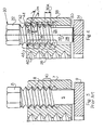
- the threaded portion 26 of the jackbolts are tapered as shown in Figure 9.
- the tapered configuration produces a metal to metal contact at point 46 under a no load condition and proceeding along the threaded portion there is an ever increasing helical volume between the confronting thread flanks until this volume is eliminated by stressing of the jackbolt.
- loading of the jackbolts proceeds from an initial load transfer site at point 46 and then proceeds by a progressive closing of the helical volume as additional thread contact is made and provides the needed increase to the capacity for load transfer.
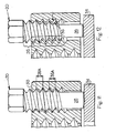
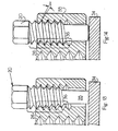
- the differential thread pitches 26A and 36A as described hereinbefore, and as shown in Figure 10 also create a helical gap of ever increasing volume commencing at point 46 and extending toward the compressible stressable end. Loading of the jackbolts proceed from an initial load transfer site at point 46 and then proceeds by a progressive closing of the helical volume as additional thread contact is made and provides the needed increase to the capacity for load transfer.
- the combination of tapering threads and differential thread pitches is depicted by Figure 11 where it can be seen that the combination produces a rapidly increasing helical volume as compare with the helical volume depicted in Figure 9 for a tapered thread only and Figure 10 for a differential thread.
Landscapes
- Engineering & Computer Science (AREA)
- General Engineering & Computer Science (AREA)
- Mechanical Engineering (AREA)
- Spinning Or Twisting Of Yarns (AREA)
- Lubricants (AREA)
- Forms Removed On Construction Sites Or Auxiliary Members Thereof (AREA)
Applications Claiming Priority (5)
| Application Number | Priority Date | Filing Date | Title |
|---|---|---|---|
| US290795 | 1988-12-28 | ||
| US9523398A | 1998-06-10 | 1998-06-10 | |
| US95233 | 1998-06-10 | ||
| US09/290,795 US6112396A (en) | 1998-06-10 | 1999-04-13 | Jackbolts for multi jackbolt tensioners |
| EP99927489A EP1117504B1 (fr) | 1998-06-10 | 1999-06-10 | Vis verin pour tendeur a vis verins multiples |
Related Parent Applications (2)
| Application Number | Title | Priority Date | Filing Date |
|---|---|---|---|
| EP99927489.7 Division | 1999-06-10 | ||
| EP99927489A Division EP1117504B1 (fr) | 1998-06-10 | 1999-06-10 | Vis verin pour tendeur a vis verins multiples |
Publications (3)
| Publication Number | Publication Date |
|---|---|
| EP1607172A2 true EP1607172A2 (fr) | 2005-12-21 |
| EP1607172A3 EP1607172A3 (fr) | 2007-05-09 |
| EP1607172B1 EP1607172B1 (fr) | 2009-10-07 |
Family
ID=22250832
Family Applications (1)
| Application Number | Title | Priority Date | Filing Date |
|---|---|---|---|
| EP05018078A Expired - Lifetime EP1607172B1 (fr) | 1998-06-10 | 1999-06-10 | Vis verins pour tendeur à vis verins multiples |
Country Status (4)
| Country | Link |
|---|---|
| US (1) | US6112396A (fr) |
| EP (1) | EP1607172B1 (fr) |
| DE (1) | DE69941520D1 (fr) |
| ES (1) | ES2334142T3 (fr) |
Cited By (3)
| Publication number | Priority date | Publication date | Assignee | Title |
|---|---|---|---|---|
| EP2028380A3 (fr) * | 2007-08-21 | 2010-03-03 | Steinbock Machinery Co. | Appareil de précontrainte utilisant une attache filetée |
| GB2468976A (en) * | 2009-03-26 | 2010-09-29 | Per-Christian Irgens | Dynamical flange or hot bolting clamp |
| EP2481913A1 (fr) * | 2011-01-04 | 2012-08-01 | Siemens Aktiengesellschaft | Assemblage boulonné pour connecter deux composants d'éolienne avec des boulons |
Families Citing this family (25)
| Publication number | Priority date | Publication date | Assignee | Title |
|---|---|---|---|---|
| AUPP315298A0 (en) * | 1998-04-23 | 1998-05-14 | Matthews, Norman Leslie | Improved fastener |
| AUPP890599A0 (en) * | 1999-02-26 | 1999-03-25 | Bucknell, John Wentworth | Tensioning hydraulic nuts |
| DE10125439A1 (de) * | 2001-05-25 | 2002-11-28 | Bosch Gmbh Robert | Hochdruckanschlußvorrichtung |
| US6712096B1 (en) | 2003-01-29 | 2004-03-30 | Kmt Waterjet Systems, Inc. | High pressure attenuator |
| US7736579B2 (en) * | 2006-07-21 | 2010-06-15 | Quadrant Epp Ag | Production of UHMWPE sheet materials |
| US7758796B2 (en) * | 2006-07-21 | 2010-07-20 | Quadrant Epp Ag | Production of UHMWPE sheet materials |
| US7758797B2 (en) * | 2006-07-21 | 2010-07-20 | Quadrant Epp Ag | Production of UHMWPE sheet materials |
| US7803450B2 (en) * | 2006-07-21 | 2010-09-28 | Quadrant Epp Ag | Production of UHMWPE sheet materials |
| US9038664B2 (en) * | 2007-11-20 | 2015-05-26 | Fisher Controls International Llc | Fluid flow control device having a seat ring retainer |
| US20100000375A1 (en) | 2008-07-07 | 2010-01-07 | Steinbock Robert C | Tamper resistant jackbolts for a tensioner |
| US9573231B2 (en) | 2013-03-04 | 2017-02-21 | David Rice | Method of simultaneously tensioning multiple jackbolts of a multi-jackbolt tensioner and handheld apparatus for performing same |
| JP2016205520A (ja) * | 2015-04-23 | 2016-12-08 | 株式会社NejiLaw | 螺合構造、雄ねじ部及び雌ねじ部 |
| US9951818B2 (en) | 2015-05-13 | 2018-04-24 | Wind Solutions, LLC. | Wind turbine yaw bearing pre-load |
| EP3454990B1 (fr) * | 2016-05-10 | 2020-06-24 | FLSmidth A/S | Ensemble boulon de verrouillage pour un dispositif de broyage |
| WO2017218870A1 (fr) | 2016-06-16 | 2017-12-21 | Superbolt, Inc. | Améliorations apportées à des tensionneurs à vérins multiples |
| EA036996B1 (ru) * | 2016-10-03 | 2021-01-25 | Плоке Инжиниринг Аг | Нажимной болт предварительно напряженного элемента и предварительно напряженный элемент с несколькими такими нажимными болтами, а также основные элементы с несколькими такими нажимными болтами предварительно напряженного элемента |
| JP6934161B2 (ja) * | 2017-02-24 | 2021-09-15 | ボルトエンジニア株式会社 | 締結構造 |
| US11285573B2 (en) | 2017-12-20 | 2022-03-29 | Superbolt, Inc. | Multiple chamber hydraulic multi-jack bolt tensioners |
| DE102019111237B4 (de) | 2019-02-18 | 2020-11-19 | Dietmar Schnier | Zweiteilige Schraubenmutter mit hoher Andrückkraft |
| CN113120021A (zh) * | 2021-05-25 | 2021-07-16 | 中车南京浦镇车辆有限公司 | 一种紧凑空间下小紧固扭矩顶推的车钩缓冲装置安装结构 |
| US11389916B1 (en) * | 2021-09-23 | 2022-07-19 | Caterpillar Inc. | Systems and methods for assembling or disassembling a hammer tool |
| DE102021211414A1 (de) * | 2021-10-11 | 2023-04-13 | Zf Friedrichshafen Ag | Getriebeanordnung umfassend ein Getriebegehäuse und einen Aufnahmeraum zur Aufnahme einer elektronischen und/oder elektrischen Funktionseinheit |
| US12553550B2 (en) * | 2021-11-15 | 2026-02-17 | Spm Oil & Gas Inc. | Tensioner and method of using same |
| USD1015863S1 (en) | 2022-05-20 | 2024-02-27 | Nord-Lock Switzerland Gmbh | Fastening device |
| DE102024128281A1 (de) * | 2024-09-30 | 2026-04-02 | Porsche Ebike Performance Gmbh | Bauteil und Baugruppe für eine Antriebsvorrichtung eines Elektrofahrrads und Antriebsvorrichtung für ein Elektrofahrrad |
Citations (1)
| Publication number | Priority date | Publication date | Assignee | Title |
|---|---|---|---|---|
| US4846614A (en) | 1986-12-08 | 1989-07-11 | Rolf Steinbock | Differential thread for transfer of screw thread forces |
Family Cites Families (11)
| Publication number | Priority date | Publication date | Assignee | Title |
|---|---|---|---|---|
| US33490A (en) * | 1861-10-15 | Improved washing-machine | ||
| US3205756A (en) * | 1962-12-31 | 1965-09-14 | Standard Pressed Steel Co | Thread system |
| US4191486A (en) * | 1978-09-06 | 1980-03-04 | Union Carbide Corporation | Threaded connections |
| US4671324A (en) * | 1982-09-01 | 1987-06-09 | Neill David C | Jack bolt assembly |
| DE3248696A1 (de) * | 1982-12-30 | 1984-07-05 | Kraftwerk Union AG, 4330 Mülheim | Schraubverbindung zwischen mutter und axial vorgespanntem bolzen |
| US4622730A (en) * | 1984-03-30 | 1986-11-18 | Rolf Steinbock | Apparatus to mechanically stress a bolt-type fastener |
| USRE33490E (en) | 1984-03-30 | 1990-12-18 | Apparatus to mechanically stress a bolt-type fastener | |
| US4927305A (en) * | 1988-09-02 | 1990-05-22 | Peterson Charles D | Tightening device for threaded connectors |
| US5069587A (en) * | 1990-06-13 | 1991-12-03 | Dresser Industries, Inc. | Securing nut apparatus |
| US5075950A (en) * | 1990-06-28 | 1991-12-31 | Steinbock Rolf H | Method for loosening jack bolts |
| US5083889A (en) * | 1990-10-04 | 1992-01-28 | Steinbock Rolf H | Structure for preventing escape of jack bolts in apparatus to mechanically stress a bolt-type fastener |
-
1999
- 1999-04-13 US US09/290,795 patent/US6112396A/en not_active Expired - Lifetime
- 1999-06-10 ES ES05018078T patent/ES2334142T3/es not_active Expired - Lifetime
- 1999-06-10 EP EP05018078A patent/EP1607172B1/fr not_active Expired - Lifetime
- 1999-06-10 DE DE69941520T patent/DE69941520D1/de not_active Expired - Lifetime
Patent Citations (1)
| Publication number | Priority date | Publication date | Assignee | Title |
|---|---|---|---|---|
| US4846614A (en) | 1986-12-08 | 1989-07-11 | Rolf Steinbock | Differential thread for transfer of screw thread forces |
Cited By (6)
| Publication number | Priority date | Publication date | Assignee | Title |
|---|---|---|---|---|
| EP2028380A3 (fr) * | 2007-08-21 | 2010-03-03 | Steinbock Machinery Co. | Appareil de précontrainte utilisant une attache filetée |
| CN101487489B (zh) * | 2007-08-21 | 2013-02-06 | 诺德-洛克瑞士股份有限公司 | 使用劈开的螺纹紧固件加预应力的装置 |
| GB2468976A (en) * | 2009-03-26 | 2010-09-29 | Per-Christian Irgens | Dynamical flange or hot bolting clamp |
| GB2468976B (en) * | 2009-03-26 | 2011-06-29 | Per-Christian Irgens | Hot bolting clamp |
| EP2481913A1 (fr) * | 2011-01-04 | 2012-08-01 | Siemens Aktiengesellschaft | Assemblage boulonné pour connecter deux composants d'éolienne avec des boulons |
| US9068558B2 (en) | 2011-01-04 | 2015-06-30 | Siemens Aktiengesellschaft | Bolted connection for connecting two wind turbine components by bolts |
Also Published As
| Publication number | Publication date |
|---|---|
| ES2334142T3 (es) | 2010-03-05 |
| EP1607172A3 (fr) | 2007-05-09 |
| DE69941520D1 (de) | 2009-11-19 |
| US6112396A (en) | 2000-09-05 |
| EP1607172B1 (fr) | 2009-10-07 |
Similar Documents
| Publication | Publication Date | Title |
|---|---|---|
| US6263764B1 (en) | Jackbolts for multi jackbolt tensioners | |
| EP1607172B1 (fr) | Vis verins pour tendeur à vis verins multiples | |
| US4346920A (en) | Threaded connection using variable lead threads | |
| US4846614A (en) | Differential thread for transfer of screw thread forces | |
| US5282707A (en) | Fastening system for locking nut with torque indicating marks | |
| CN201582286U (zh) | 先进的螺母及螺栓 | |
| US2754871A (en) | Self-locking nut having a radially deformed thread portion and method for the production of the same | |
| EP2069647B1 (fr) | Organe de fixation indiquant la charge et procédé de fabrication | |
| EP2302224B1 (fr) | Structure de fixation de vis avec vis auto-foreuse à résistance élevée | |
| US6955475B2 (en) | Bearing apparatus for a driving wheel of vehicle | |
| US20050155212A1 (en) | Method of fastening | |
| CN103089896B (zh) | 联结方法及缸体装置 | |
| US4806054A (en) | Male threaded fastener capable of use with a swaged collar | |
| US20050276656A1 (en) | Joint assembly | |
| EP0060508A1 (fr) | Boulon fileté et procédé pour sa fabrication | |
| US20090110510A1 (en) | Washer including protrusions for use in a fastener assembly | |
| EP1886031B1 (fr) | Piece de fixation et procede de reduction d'une defaillance due a une contrainte dans un organe de moteur | |
| CN113898656A (zh) | 防松连接结构及机车 | |
| CN121738984A (zh) | 一种超高压抗拉紧固件 | |
| EP1778987B1 (fr) | Contre-ecrou facile a mettre en place e difficile a retirer | |
| CN116044883B (zh) | 一种螺母自锁方法及其自锁结构 | |
| KR20210031982A (ko) | 작은 축방향 힘의 밀봉 시스템 | |
| CN221569166U (zh) | 一种双螺母防松结构 | |
| CN119712750B (zh) | 一种具备自适应调节的波形垫圈 | |
| US6241443B1 (en) | Fastener with staged locking system |
Legal Events
| Date | Code | Title | Description |
|---|---|---|---|
| PUAI | Public reference made under article 153(3) epc to a published international application that has entered the european phase |
Free format text: ORIGINAL CODE: 0009012 |
|
| AC | Divisional application: reference to earlier application |
Ref document number: 1117504 Country of ref document: EP Kind code of ref document: P |
|
| AK | Designated contracting states |
Kind code of ref document: A2 Designated state(s): DE ES FR GB IT |
|
| RIN1 | Information on inventor provided before grant (corrected) |
Inventor name: STEINBOCK, ROLF. H. |
|
| RIN1 | Information on inventor provided before grant (corrected) |
Inventor name: STEINBOCK, ROLF. H. |
|
| PUAL | Search report despatched |
Free format text: ORIGINAL CODE: 0009013 |
|
| AK | Designated contracting states |
Kind code of ref document: A3 Designated state(s): DE ES FR GB IT |
|
| 17P | Request for examination filed |
Effective date: 20071106 |
|
| AKX | Designation fees paid |
Designated state(s): DE ES FR GB IT |
|
| 17Q | First examination report despatched |
Effective date: 20080118 |
|
| GRAP | Despatch of communication of intention to grant a patent |
Free format text: ORIGINAL CODE: EPIDOSNIGR1 |
|
| GRAS | Grant fee paid |
Free format text: ORIGINAL CODE: EPIDOSNIGR3 |
|
| GRAA | (expected) grant |
Free format text: ORIGINAL CODE: 0009210 |
|
| AC | Divisional application: reference to earlier application |
Ref document number: 1117504 Country of ref document: EP Kind code of ref document: P |
|
| AK | Designated contracting states |
Kind code of ref document: B1 Designated state(s): DE ES FR GB IT |
|
| REG | Reference to a national code |
Ref country code: GB Ref legal event code: FG4D |
|
| REF | Corresponds to: |
Ref document number: 69941520 Country of ref document: DE Date of ref document: 20091119 Kind code of ref document: P |
|
| REG | Reference to a national code |
Ref country code: ES Ref legal event code: FG2A Ref document number: 2334142 Country of ref document: ES Kind code of ref document: T3 |
|
| PLBE | No opposition filed within time limit |
Free format text: ORIGINAL CODE: 0009261 |
|
| STAA | Information on the status of an ep patent application or granted ep patent |
Free format text: STATUS: NO OPPOSITION FILED WITHIN TIME LIMIT |
|
| 26N | No opposition filed |
Effective date: 20100708 |
|
| REG | Reference to a national code |
Ref country code: DE Ref legal event code: R082 Ref document number: 69941520 Country of ref document: DE Representative=s name: VOSSIUS & PARTNER, DE |
|
| REG | Reference to a national code |
Ref country code: DE Ref legal event code: R081 Ref document number: 69941520 Country of ref document: DE Owner name: NORD-LOCK SWITZERLAND GMBH, CH Free format text: FORMER OWNER: STEINBOCK MACHINERY CO., PITTBURGH, PA., US Effective date: 20120113 Ref country code: DE Ref legal event code: R082 Ref document number: 69941520 Country of ref document: DE Representative=s name: VOSSIUS & PARTNER PATENTANWAELTE RECHTSANWAELT, DE Effective date: 20120113 |
|
| REG | Reference to a national code |
Ref country code: ES Ref legal event code: PC2A Owner name: NORD-LOCK SWITZERLAND GMBH Effective date: 20120315 |
|
| REG | Reference to a national code |
Ref country code: FR Ref legal event code: TP Owner name: NORD-LOCK SWITZERLAND GMBH, CH Effective date: 20120529 |
|
| REG | Reference to a national code |
Ref country code: FR Ref legal event code: PLFP Year of fee payment: 18 |
|
| REG | Reference to a national code |
Ref country code: FR Ref legal event code: PLFP Year of fee payment: 19 |
|
| REG | Reference to a national code |
Ref country code: FR Ref legal event code: PLFP Year of fee payment: 20 |
|
| PGFP | Annual fee paid to national office [announced via postgrant information from national office to epo] |
Ref country code: DE Payment date: 20180619 Year of fee payment: 20 |
|
| PGFP | Annual fee paid to national office [announced via postgrant information from national office to epo] |
Ref country code: IT Payment date: 20180620 Year of fee payment: 20 Ref country code: FR Payment date: 20180615 Year of fee payment: 20 |
|
| PGFP | Annual fee paid to national office [announced via postgrant information from national office to epo] |
Ref country code: GB Payment date: 20180618 Year of fee payment: 20 Ref country code: ES Payment date: 20180702 Year of fee payment: 20 |
|
| REG | Reference to a national code |
Ref country code: DE Ref legal event code: R071 Ref document number: 69941520 Country of ref document: DE |
|
| REG | Reference to a national code |
Ref country code: GB Ref legal event code: PE20 Expiry date: 20190609 |
|
| PG25 | Lapsed in a contracting state [announced via postgrant information from national office to epo] |
Ref country code: GB Free format text: LAPSE BECAUSE OF EXPIRATION OF PROTECTION Effective date: 20190609 |
|
| REG | Reference to a national code |
Ref country code: ES Ref legal event code: FD2A Effective date: 20201106 |
|
| PG25 | Lapsed in a contracting state [announced via postgrant information from national office to epo] |
Ref country code: ES Free format text: LAPSE BECAUSE OF EXPIRATION OF PROTECTION Effective date: 20190611 |