EP1607181B1 - Schleifkörper - Google Patents
Schleifkörper Download PDFInfo
- Publication number
- EP1607181B1 EP1607181B1 EP04425440A EP04425440A EP1607181B1 EP 1607181 B1 EP1607181 B1 EP 1607181B1 EP 04425440 A EP04425440 A EP 04425440A EP 04425440 A EP04425440 A EP 04425440A EP 1607181 B1 EP1607181 B1 EP 1607181B1
- Authority
- EP
- European Patent Office
- Prior art keywords
- abrasive body
- abrasive
- tongues
- central portion
- anyone
- Prior art date
- Legal status (The legal status is an assumption and is not a legal conclusion. Google has not performed a legal analysis and makes no representation as to the accuracy of the status listed.)
- Expired - Lifetime
Links
- 210000002105 tongue Anatomy 0.000 claims abstract description 30
- 239000000463 material Substances 0.000 claims abstract description 21
- 239000013013 elastic material Substances 0.000 claims abstract description 6
- 239000000843 powder Substances 0.000 claims description 8
- 238000005299 abrasion Methods 0.000 claims description 4
- 239000000853 adhesive Substances 0.000 claims description 3
- 230000001070 adhesive effect Effects 0.000 claims description 3
- 239000004744 fabric Substances 0.000 claims description 3
- 238000010276 construction Methods 0.000 claims description 2
- 239000002245 particle Substances 0.000 claims 1
- 238000004519 manufacturing process Methods 0.000 abstract description 9
- 239000003082 abrasive agent Substances 0.000 description 7
- 239000000243 solution Substances 0.000 description 5
- 239000007767 bonding agent Substances 0.000 description 4
- 230000002093 peripheral effect Effects 0.000 description 4
- 230000009471 action Effects 0.000 description 2
- 239000008187 granular material Substances 0.000 description 2
- 238000000926 separation method Methods 0.000 description 2
- 238000011282 treatment Methods 0.000 description 2
- 239000002023 wood Substances 0.000 description 2
- 230000008859 change Effects 0.000 description 1
- 230000008878 coupling Effects 0.000 description 1
- 238000010168 coupling process Methods 0.000 description 1
- 238000005859 coupling reaction Methods 0.000 description 1
- 239000006185 dispersion Substances 0.000 description 1
- 238000005516 engineering process Methods 0.000 description 1
- 238000001746 injection moulding Methods 0.000 description 1
- 238000010422 painting Methods 0.000 description 1
- 229920002635 polyurethane Polymers 0.000 description 1
- 239000004814 polyurethane Substances 0.000 description 1
- 239000011347 resin Substances 0.000 description 1
- 229920005989 resin Polymers 0.000 description 1
- 230000007480 spreading Effects 0.000 description 1
- 239000004575 stone Substances 0.000 description 1
Images

Classifications
-
- B—PERFORMING OPERATIONS; TRANSPORTING
- B24—GRINDING; POLISHING
- B24B—MACHINES, DEVICES, OR PROCESSES FOR GRINDING OR POLISHING; DRESSING OR CONDITIONING OF ABRADING SURFACES; FEEDING OF GRINDING, POLISHING, OR LAPPING AGENTS
- B24B23/00—Portable grinding machines, e.g. hand-guided; Accessories therefor
- B24B23/02—Portable grinding machines, e.g. hand-guided; Accessories therefor with rotating grinding tools; Accessories therefor
-
- B—PERFORMING OPERATIONS; TRANSPORTING
- B24—GRINDING; POLISHING
- B24D—TOOLS FOR GRINDING, BUFFING OR SHARPENING
- B24D11/00—Constructional features of flexible abrasive materials; Special features in the manufacture of such materials
- B24D11/02—Backings, e.g. foils, webs, mesh fabrics
-
- B—PERFORMING OPERATIONS; TRANSPORTING
- B24—GRINDING; POLISHING
- B24D—TOOLS FOR GRINDING, BUFFING OR SHARPENING
- B24D9/00—Wheels or drums supporting in exchangeable arrangement a layer of flexible abrasive material, e.g. sandpaper
- B24D9/08—Circular back-plates for carrying flexible material
- B24D9/085—Devices for mounting sheets on a backing plate
Definitions
- the present invention relates to an abrasive body set to be used in machines designed to carry out working operations by abrasion; in particular the abrasive or sanding disks in accordance with the invention are intended for surface finishing of manufactured articles or for preparing predetermined treatments of same.
- the apparatus of known type generally have a load bearing machine body to first of all bear a corresponding supporting wheel and to set the latter in rotation around an axis thereof.
- the supporting wheel is in turn such envisaged as to be able to receive a suitable sanding disk in engagement, said disk having a work surface that, under operating conditions, is designed to face the article of manufacture to be worked.
- This work surface carries the necessary abrasive material to enable working by material removal.
- the above machines can also enable suction of the powders generated by the action of the abrasive body on the surface being worked and conveying of said powders to appropriate collection regions to allow a healthier and cleaner work environment.
- sanding disks consisting of a support of paper material carrying the abrasive material, said disks being connected with the respective supporting wheel by an adhesive or a coupling involving use of a tape fastener of the so-called "Velcro" type.
- the sanding disk too must have holes of the same features as those of the supporting wheel and in register with the latter to allow passage of the abrasive powders.
- the sanding disks in accordance with this type of solution are made of paper or cloth material and are brought into engagement with the respective supporting wheel by turning the tongues down and engaging them through the holes to the corresponding pins integral with the supporting wheel.
- a supporting wheel having a perimeter portion made of deformable material enables engagement between the sanding disk and the supporting wheel; the presence of tongues and the respective pins allows the suction holes of the sanding disk and those of the supporting wheel to be in register.
- the present invention aims at making available a sanding disk according to claim 1, ensuring an optimal grip on the supporting wheel also during the operations for material removal.
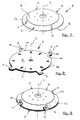
- an abrasive body in accordance with the present invention has been generally identified by reference numeral 1.
- the abrasive body therein shown consists of a central portion 4 of a substantially disk-shaped conformation having a lower work surface 2 that under operating conditions is designed to enable material removal from the surface of an article of manufacture to be finished off.
- the work surface 2 will be provided with the suitable abrasive or sanding means 3 at least at the central portion 4 of body 1, which means will consist of appropriate granules of abrasive material applied to said work surface.
- tongues may be provided, that possibly may not be spaced apart the same distance from each other, provided they are able to ensure a substantially steady engagement of the sanding disk with the supporting wheel.
- the tongues 5 and central portion 4 of the abrasive body 1 are of one piece construction and in particular can be manufactured by injection moulding from an appropriate polyurethane material (obviously other materials and other manufacturing technologies can be also adopted).
- the abrasive body 1 can be made of several parts separated from each other, e.g. the tongues 5 separated from the central portion 4 to which they are then linked by means of bonding agents or by other systems.
- the abrasive body 1 will be made (at least partly or preferably fully) of an elastically deformable material.
- deformations can take place in the extension plane of the central portion 4 of the abrasive body without involving breaks and tears on the disk.
- tongues 5 or part of the central portion 4 can be made of elastically deformable material, depending on the operating requirements.
- abrasive means 3 can be alternatively dispersed at the inside of the abrasive disk, only in the central portion 4 thereof, for example (being injected in the abrasive body during the manufacturing step) or alternatively, said abrasive means can be engaged by suitable resins or bonding agents exclusively at the work surface 2 of the abrasive body itself.
- the elastic disk When the abrasive means 3 is dispersed in the central portion 4 of disk 1, the elastic disk will have a longer duration than the sanding disks of known type; in fact, simultaneously with consumption of the abrasive means on the surface, also the elastic material in which the abrasive means is buried will be used up, which will cause the abrasive material buried in the region just below the work surface to go up to the surface. Therefore the disk will have to be replaced at a later time than the disks of standard type.
- sanding disks can be produced that are substantially impervious to passage of the abraded powder and in which the granules of abrasive material are directly engaged or not on the surface of the elastic material.
- a plurality of passage holes 14 can be provided on the sanding disk which holes are adapted to enable suction of the scraped off material by a machine 20 of known type (see Fig. 4 ); said holes 14 must therefore necessarily be in register with the respective holes present in the supporting wheel.
- a suitable thickness of the sanding disk 1 can be established a priori and said disk can reach a thickness of 80 mm for example, depending on requirements.
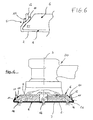
- the support 6 will have respective pins 12 emerging from its upper surface 7 adapted, under engagement conditions, to pass through said cuts 9.
- one of the adjacent edges 11 is in the form of a convex tab and, under operating conditions, it exerts pressure against the respective pin 12 thereby improving the engaging steadiness between the two parts (see Fig. 6 ).
- the elastic character of the abrasive body can be utilised to promote engagement of same with the supporting wheel.
- the tongues 5 and/or central portion 4 of the abrasive body 1 can be elastically deformed to enable quick engagement of pins 12 in the respective cuts 9 while at the same time maintaining the sanding disk tensioned on the supporting wheel.
- the particular configuration taken during the engagement step makes it impossible to disengage the sanding disk 1 from the supporting wheel 6 even as a result of possible deformations of the peripheral portion 21 of the supporting wheel 6 (which deformable portion enables the shape of the article of manufacture under working to be better followed and therefore improved finishing features and tensioning of the disk to be ensured), so that the operating reliability of the whole device is increased.
- the abrasive body being the object of the invention is adapted to be mounted both on completely rigid supporting wheels and on supporting wheels having a deformable peripheral portion, due to exploitation of the intrinsic elasticity/deformability features of the sanding disk itself.
- the abrasive body of the invention at the upper surface of the central disk-shaped portion 4 has no means for engagement with the supporting wheels such as adhesive means, bonding agents or tape fasteners of the "Velcro" type.
- the abrasive body in accordance with the invention will be connected with the supporting wheel 6 exclusively by means of tongues 5, while the central portion 4 will be movable and will not be linked to the lower surface of the supporting wheel 6 itself.
- the inner deformations of the abrasive body with respect to the surface to be worked allow the workpiece to be better finished through creation of movements adapted to reduce and even eliminate clogging of the sanding disk.
- the supporting wheel 6 will be provided with corresponding hooking portions 22 to receive the tongues 5, as shown in said figure.
- the invention achieves important advantages.
- the solution involving dispersion of the abrasive material within the spongy body increases duration of the disk as compared with the sanding disks present on the market.
Landscapes
- Engineering & Computer Science (AREA)
- Mechanical Engineering (AREA)
- Polishing Bodies And Polishing Tools (AREA)
Claims (13)
- Schleifkörper, umfassend:- eine Arbeitsoberfläche (2), ausgelegt, um unter Arbeitsbedingungen zu einer Oberfläche, die bearbeitet werden soll, zu zeigen;- Schleifmittel (3), das zumindest mit einem zentralen Teil (4) des Schleifkörpers (1) assoziiert ist, um die Bearbeitung durch Schleifen zu ermöglichen; und- eine vorbestimmte Anzahl von Zungen (5), die aus dem zentralen Bereich (4) des Schleifkörpers (1) hervortreten, um die Verbindung des Schleifkörpers selbst mit einer Unterstützung (6) zu ermöglichen, gekennzeichnet dadurch, dass der Schleifkörper (1) zumindest teilweise aus elastisch deformierbarem Material besteht, das im Wesentlichen undurchlässig für den Durchgang des abgeschliffenen Puders ist.
- Schleifkörper gemäß Anspruch 1, gekennzeichnet dadurch, dass unter Verbindungsbedingungen der Zungen (5) mit der Unterstützung (6) eine obere Oberfläche (7) des Schleifkörpers (1) nicht direkt an der unteren Oberfläche (8) der Unterstützung (6) befestigt ist, durch Haftmittel oder Befestigungen zum Beispiel des "Velcro"-Typs.
- Schleifkörper gemäß einem der vorangehenden Ansprüche, gekennzeichnet dadurch, dass zumindest eine der Zungen (5) und vorzugsweise jede von diesen einen Einschnitt (9) definiert durch zueinander benachbarte Kanten (10, 11) aufweisen, wobei der Einschnitt (9) so gesetzt ist, dass die Verbindung der Zunge (5) mit dem entsprechenden Stift (12) ermöglicht wird, der aus der oberen Oberfläche (13) der Unterstützung (6) hervortritt.
- Schleifkörper gemäß einem der vorangehenden Ansprüche, gekennzeichnet dadurch, dass der zentrale Bereich (4) des Schleifkörpers (1) und die Zungen (5) eine einteilige Konstruktion haben und aus einem elastisch dehnbaren Material hergestellt sind.
- Schleifkörper gemäß einem der vorangehenden Ansprüche, gekennzeichnet dadurch, dass der zentrale Bereich (4) und die Zungen (5) separat hergestellt sind und durch entsprechende Koppelmittel aneinander befestigt sind.
- Schleifkörper gemäß einem der vorangehenden Ansprüche, gekennzeichnet dadurch, dass das Schleifmittel (3) in direkter Verbindung mit zumindest dem zentralen Bereich (4) des Schleifkörpers (1) auf der Arbeitsoberfläche (2) ist, im Besonderen ohne die Zwischeneinbringung jedweder Oberfläche aus nichtelastischem Material, wie Papiermaterial, Stoffmaterial oder andere.
- Schleifkörper gemäß einem der vorangehenden Ansprüche, gekennzeichnet dadurch, dass das Schleifmittel (3) innerhalb zumindest dem zentralen Bereich (4) des Schleifkörpers (1) zerstreut ist.
- Schleifkörper gemäß einem der vorangehenden Ansprüche, gekennzeichnet dadurch, dass er aus einem elastisch dehnbaren Material hergestellt ist und undurchdringlich ist für den Durchgang des Schleifpuders.
- Schleifkörper gemäß einem der vorangehenden Ansprüche, gekennzeichnet dadurch, dass er aus einem elastisch dehnbaren Material hergestellt ist, wobei der Schleifkörper (1) den Durchgang des Schleifpuders durch seinen zentralen Bereich (4) ermöglicht, zumindest, wenn er elastisch deformiert wird.
- Schleifkörper gemäß einem der vorangehenden Ansprüche, gekennzeichnet dadurch, dass der zentrale Bereich (4) flach ist und vollständig aus einem elastischen Material gebildet ist, das zumindest die Deformation desselben in der Dehnungsebene dessen ermöglicht.
- Schleifkörper gemäß einem der vorangehenden Ansprüche, gekennzeichnet dadurch, dass der zentrale Bereich (4) eine Vielzahl von durchgehenden Löchern (14) aufweist, um mögliches Absaugen der abgeschliffenen Partikel zu ermöglichen.
- Schleifkörper gemäß einem der vorangehenden Ansprüche, gekennzeichnet dadurch, dass zumindest die Zungen (5) aus einem elastisch deformierbaren Material bestehen, um die Verbindung mit der Unterstützung (6) zu ermöglichen.
- Schleifkörper gemäß Anspruch 3, gekennzeichnet dadurch, dass unter Verbindungsbedingungen der Zungen (5) mit den Stiften (12) der Unterstützung eine der benachbarten Kanten (11) die Form eines Streifens hat, der gegen den Stift selbst drückt.
Priority Applications (3)
| Application Number | Priority Date | Filing Date | Title |
|---|---|---|---|
| AT04425440T ATE464980T1 (de) | 2004-06-15 | 2004-06-15 | Schleifkörper |
| DE602004026700T DE602004026700D1 (de) | 2004-06-15 | 2004-06-15 | Schleifkörper |
| EP04425440A EP1607181B1 (de) | 2004-06-15 | 2004-06-15 | Schleifkörper |
Applications Claiming Priority (1)
| Application Number | Priority Date | Filing Date | Title |
|---|---|---|---|
| EP04425440A EP1607181B1 (de) | 2004-06-15 | 2004-06-15 | Schleifkörper |
Publications (2)
| Publication Number | Publication Date |
|---|---|
| EP1607181A1 EP1607181A1 (de) | 2005-12-21 |
| EP1607181B1 true EP1607181B1 (de) | 2010-04-21 |
Family
ID=34932564
Family Applications (1)
| Application Number | Title | Priority Date | Filing Date |
|---|---|---|---|
| EP04425440A Expired - Lifetime EP1607181B1 (de) | 2004-06-15 | 2004-06-15 | Schleifkörper |
Country Status (3)
| Country | Link |
|---|---|
| EP (1) | EP1607181B1 (de) |
| AT (1) | ATE464980T1 (de) |
| DE (1) | DE602004026700D1 (de) |
Families Citing this family (2)
| Publication number | Priority date | Publication date | Assignee | Title |
|---|---|---|---|---|
| US7458883B2 (en) | 2006-01-31 | 2008-12-02 | B A Werk Industries Ltd. | Apparatus for abrading a surface |
| CN119038226A (zh) * | 2024-08-09 | 2024-11-29 | 江苏益禾雨粮油食品有限公司 | 一种用于米糠膨化加工产线的上下料装置 |
Family Cites Families (3)
| Publication number | Priority date | Publication date | Assignee | Title |
|---|---|---|---|---|
| JPS62292367A (ja) * | 1986-06-11 | 1987-12-19 | Kouyoushiya:Kk | ダイヤモンド被覆弾性粒研磨シ−ト |
| IT1273769B (it) * | 1994-02-15 | 1997-07-10 | Catalfer S N C Di Catalfamo Gi | Sistema per il fissaggio laterale ai piattelli delle levigatrici rotanti dei dischi abrasivi intercambiabili |
| US5637386A (en) * | 1995-01-10 | 1997-06-10 | Norton Company | Fining abrasive materials |
-
2004
- 2004-06-15 AT AT04425440T patent/ATE464980T1/de not_active IP Right Cessation
- 2004-06-15 EP EP04425440A patent/EP1607181B1/de not_active Expired - Lifetime
- 2004-06-15 DE DE602004026700T patent/DE602004026700D1/de not_active Expired - Lifetime
Also Published As
| Publication number | Publication date |
|---|---|
| ATE464980T1 (de) | 2010-05-15 |
| DE602004026700D1 (de) | 2010-06-02 |
| EP1607181A1 (de) | 2005-12-21 |
Similar Documents
| Publication | Publication Date | Title |
|---|---|---|
| US5174795A (en) | Flexible abrasive pad with ramp edge surface | |
| US5209760A (en) | Injection molded abrasive pad | |
| US8002612B2 (en) | Attachment system for a sanding tool | |
| US6142858A (en) | Backup pad for abrasive articles | |
| US5807161A (en) | Reversible back-up pad | |
| CN101977733B (zh) | 用于修饰表面的方法、系统及装置 | |
| CA2265263C (en) | Universal abrasive disc | |
| US6361424B1 (en) | Back-up pad for abrasive articles and method of making | |
| US5454751A (en) | Marble, granite and stone finishing and abrasive pads therefor | |
| JP2001526593A (ja) | 複合研磨組立体および方法 | |
| WO1998019829A1 (en) | Multiple abrasive assembly and method | |
| EP2262613B1 (de) | Eine adapteranordnung zur modifizierung von flächen verwendende(s) verfahren, vorrichtung und system | |
| EP1177071B1 (de) | Schleifscheibe mit stützteller | |
| EP0111765A3 (en) | Abrasive product with an extensible and flexible backing, method for its manufacture and its use | |
| WO2005087436A1 (en) | Sanding element | |
| AU2005336407B2 (en) | Abrasive body | |
| EP1607181A1 (de) | Schleifkörper | |
| RU2392105C2 (ru) | Абразивная насадка | |
| JP2005305603A (ja) | ハンディグラインダー用研磨ディスク | |
| KR20130127732A (ko) | 연마용 시트 | |
| KR20140140357A (ko) | 연마 디스크 | |
| JPH06246643A (ja) | 研磨体 | |
| MXPA01006177A (en) | Grinding disc with backup pad |
Legal Events
| Date | Code | Title | Description |
|---|---|---|---|
| PUAI | Public reference made under article 153(3) epc to a published international application that has entered the european phase |
Free format text: ORIGINAL CODE: 0009012 |
|
| AK | Designated contracting states |
Kind code of ref document: A1 Designated state(s): AT BE BG CH CY CZ DE DK EE ES FI FR GB GR HU IE IT LI LU MC NL PL PT RO SE SI SK TR |
|
| AX | Request for extension of the european patent |
Extension state: AL HR LT LV MK |
|
| 17P | Request for examination filed |
Effective date: 20051219 |
|
| RAP1 | Party data changed (applicant data changed or rights of an application transferred) |
Owner name: CATALFAMO, PASQUALE |
|
| RIN1 | Information on inventor provided before grant (corrected) |
Inventor name: CATALFAMO, GIUSEPPE |
|
| AKX | Designation fees paid |
Designated state(s): AT BE BG CH CY CZ DE DK EE ES FI FR GB GR HU IE IT LI LU MC NL PL PT RO SE SI SK TR |
|
| AXX | Extension fees paid |
Extension state: LT Payment date: 20060619 Extension state: LV Payment date: 20060619 Extension state: HR Payment date: 20060619 |
|
| 17Q | First examination report despatched |
Effective date: 20090227 |
|
| GRAP | Despatch of communication of intention to grant a patent |
Free format text: ORIGINAL CODE: EPIDOSNIGR1 |
|
| GRAS | Grant fee paid |
Free format text: ORIGINAL CODE: EPIDOSNIGR3 |
|
| GRAA | (expected) grant |
Free format text: ORIGINAL CODE: 0009210 |
|
| AK | Designated contracting states |
Kind code of ref document: B1 Designated state(s): AT BE BG CH CY CZ DE DK EE ES FI FR GB GR HU IE IT LI LU MC NL PL PT RO SE SI SK TR |
|
| AX | Request for extension of the european patent |
Extension state: HR LT LV |
|
| REG | Reference to a national code |
Ref country code: GB Ref legal event code: FG4D |
|
| REG | Reference to a national code |
Ref country code: CH Ref legal event code: EP |
|
| REG | Reference to a national code |
Ref country code: IE Ref legal event code: FG4D |
|
| REF | Corresponds to: |
Ref document number: 602004026700 Country of ref document: DE Date of ref document: 20100602 Kind code of ref document: P |
|
| REG | Reference to a national code |
Ref country code: NL Ref legal event code: VDEP Effective date: 20100421 |
|
| LTIE | Lt: invalidation of european patent or patent extension |
Effective date: 20100421 |
|
| PG25 | Lapsed in a contracting state [announced via postgrant information from national office to epo] |
Ref country code: NL Free format text: LAPSE BECAUSE OF FAILURE TO SUBMIT A TRANSLATION OF THE DESCRIPTION OR TO PAY THE FEE WITHIN THE PRESCRIBED TIME-LIMIT Effective date: 20100421 Ref country code: ES Free format text: LAPSE BECAUSE OF FAILURE TO SUBMIT A TRANSLATION OF THE DESCRIPTION OR TO PAY THE FEE WITHIN THE PRESCRIBED TIME-LIMIT Effective date: 20100801 Ref country code: SE Free format text: LAPSE BECAUSE OF FAILURE TO SUBMIT A TRANSLATION OF THE DESCRIPTION OR TO PAY THE FEE WITHIN THE PRESCRIBED TIME-LIMIT Effective date: 20100421 |
|
| PG25 | Lapsed in a contracting state [announced via postgrant information from national office to epo] |
Ref country code: AT Free format text: LAPSE BECAUSE OF FAILURE TO SUBMIT A TRANSLATION OF THE DESCRIPTION OR TO PAY THE FEE WITHIN THE PRESCRIBED TIME-LIMIT Effective date: 20100421 Ref country code: FI Free format text: LAPSE BECAUSE OF FAILURE TO SUBMIT A TRANSLATION OF THE DESCRIPTION OR TO PAY THE FEE WITHIN THE PRESCRIBED TIME-LIMIT Effective date: 20100421 Ref country code: SI Free format text: LAPSE BECAUSE OF FAILURE TO SUBMIT A TRANSLATION OF THE DESCRIPTION OR TO PAY THE FEE WITHIN THE PRESCRIBED TIME-LIMIT Effective date: 20100421 |
|
| PG25 | Lapsed in a contracting state [announced via postgrant information from national office to epo] |
Ref country code: PL Free format text: LAPSE BECAUSE OF FAILURE TO SUBMIT A TRANSLATION OF THE DESCRIPTION OR TO PAY THE FEE WITHIN THE PRESCRIBED TIME-LIMIT Effective date: 20100421 Ref country code: GR Free format text: LAPSE BECAUSE OF FAILURE TO SUBMIT A TRANSLATION OF THE DESCRIPTION OR TO PAY THE FEE WITHIN THE PRESCRIBED TIME-LIMIT Effective date: 20100722 Ref country code: CY Free format text: LAPSE BECAUSE OF FAILURE TO SUBMIT A TRANSLATION OF THE DESCRIPTION OR TO PAY THE FEE WITHIN THE PRESCRIBED TIME-LIMIT Effective date: 20100428 |
|
| PG25 | Lapsed in a contracting state [announced via postgrant information from national office to epo] |
Ref country code: PT Free format text: LAPSE BECAUSE OF FAILURE TO SUBMIT A TRANSLATION OF THE DESCRIPTION OR TO PAY THE FEE WITHIN THE PRESCRIBED TIME-LIMIT Effective date: 20100823 Ref country code: DK Free format text: LAPSE BECAUSE OF FAILURE TO SUBMIT A TRANSLATION OF THE DESCRIPTION OR TO PAY THE FEE WITHIN THE PRESCRIBED TIME-LIMIT Effective date: 20100421 Ref country code: EE Free format text: LAPSE BECAUSE OF FAILURE TO SUBMIT A TRANSLATION OF THE DESCRIPTION OR TO PAY THE FEE WITHIN THE PRESCRIBED TIME-LIMIT Effective date: 20100421 Ref country code: MC Free format text: LAPSE BECAUSE OF NON-PAYMENT OF DUE FEES Effective date: 20100630 |
|
| REG | Reference to a national code |
Ref country code: CH Ref legal event code: PL |
|
| PLBE | No opposition filed within time limit |
Free format text: ORIGINAL CODE: 0009261 |
|
| STAA | Information on the status of an ep patent application or granted ep patent |
Free format text: STATUS: NO OPPOSITION FILED WITHIN TIME LIMIT |
|
| PG25 | Lapsed in a contracting state [announced via postgrant information from national office to epo] |
Ref country code: CZ Free format text: LAPSE BECAUSE OF FAILURE TO SUBMIT A TRANSLATION OF THE DESCRIPTION OR TO PAY THE FEE WITHIN THE PRESCRIBED TIME-LIMIT Effective date: 20100421 Ref country code: SK Free format text: LAPSE BECAUSE OF FAILURE TO SUBMIT A TRANSLATION OF THE DESCRIPTION OR TO PAY THE FEE WITHIN THE PRESCRIBED TIME-LIMIT Effective date: 20100421 Ref country code: RO Free format text: LAPSE BECAUSE OF FAILURE TO SUBMIT A TRANSLATION OF THE DESCRIPTION OR TO PAY THE FEE WITHIN THE PRESCRIBED TIME-LIMIT Effective date: 20100421 Ref country code: BE Free format text: LAPSE BECAUSE OF FAILURE TO SUBMIT A TRANSLATION OF THE DESCRIPTION OR TO PAY THE FEE WITHIN THE PRESCRIBED TIME-LIMIT Effective date: 20100421 |
|
| 26N | No opposition filed |
Effective date: 20110124 |
|
| PG25 | Lapsed in a contracting state [announced via postgrant information from national office to epo] |
Ref country code: CH Free format text: LAPSE BECAUSE OF NON-PAYMENT OF DUE FEES Effective date: 20100630 Ref country code: LI Free format text: LAPSE BECAUSE OF NON-PAYMENT OF DUE FEES Effective date: 20100630 Ref country code: IE Free format text: LAPSE BECAUSE OF NON-PAYMENT OF DUE FEES Effective date: 20100615 |
|
| PG25 | Lapsed in a contracting state [announced via postgrant information from national office to epo] |
Ref country code: LU Free format text: LAPSE BECAUSE OF NON-PAYMENT OF DUE FEES Effective date: 20100615 Ref country code: BG Free format text: LAPSE BECAUSE OF FAILURE TO SUBMIT A TRANSLATION OF THE DESCRIPTION OR TO PAY THE FEE WITHIN THE PRESCRIBED TIME-LIMIT Effective date: 20100421 Ref country code: HU Free format text: LAPSE BECAUSE OF FAILURE TO SUBMIT A TRANSLATION OF THE DESCRIPTION OR TO PAY THE FEE WITHIN THE PRESCRIBED TIME-LIMIT Effective date: 20101022 |
|
| PG25 | Lapsed in a contracting state [announced via postgrant information from national office to epo] |
Ref country code: TR Free format text: LAPSE BECAUSE OF FAILURE TO SUBMIT A TRANSLATION OF THE DESCRIPTION OR TO PAY THE FEE WITHIN THE PRESCRIBED TIME-LIMIT Effective date: 20100421 |
|
| PG25 | Lapsed in a contracting state [announced via postgrant information from national office to epo] |
Ref country code: BG Free format text: LAPSE BECAUSE OF FAILURE TO SUBMIT A TRANSLATION OF THE DESCRIPTION OR TO PAY THE FEE WITHIN THE PRESCRIBED TIME-LIMIT Effective date: 20100721 |
|
| PGFP | Annual fee paid to national office [announced via postgrant information from national office to epo] |
Ref country code: GB Payment date: 20140611 Year of fee payment: 11 |
|
| PGFP | Annual fee paid to national office [announced via postgrant information from national office to epo] |
Ref country code: IT Payment date: 20140620 Year of fee payment: 11 Ref country code: DE Payment date: 20140611 Year of fee payment: 11 |
|
| PGFP | Annual fee paid to national office [announced via postgrant information from national office to epo] |
Ref country code: FR Payment date: 20140609 Year of fee payment: 11 |
|
| REG | Reference to a national code |
Ref country code: DE Ref legal event code: R119 Ref document number: 602004026700 Country of ref document: DE |
|
| PG25 | Lapsed in a contracting state [announced via postgrant information from national office to epo] |
Ref country code: IT Free format text: LAPSE BECAUSE OF NON-PAYMENT OF DUE FEES Effective date: 20150615 |
|
| GBPC | Gb: european patent ceased through non-payment of renewal fee |
Effective date: 20150615 |
|
| REG | Reference to a national code |
Ref country code: FR Ref legal event code: ST Effective date: 20160229 |
|
| PG25 | Lapsed in a contracting state [announced via postgrant information from national office to epo] |
Ref country code: GB Free format text: LAPSE BECAUSE OF NON-PAYMENT OF DUE FEES Effective date: 20150615 Ref country code: DE Free format text: LAPSE BECAUSE OF NON-PAYMENT OF DUE FEES Effective date: 20160101 |
|
| PG25 | Lapsed in a contracting state [announced via postgrant information from national office to epo] |
Ref country code: FR Free format text: LAPSE BECAUSE OF NON-PAYMENT OF DUE FEES Effective date: 20150630 |