EP1607680A1 - Brennkammer mit Oberluftinjektion - Google Patents
Brennkammer mit Oberluftinjektion Download PDFInfo
- Publication number
- EP1607680A1 EP1607680A1 EP05253579A EP05253579A EP1607680A1 EP 1607680 A1 EP1607680 A1 EP 1607680A1 EP 05253579 A EP05253579 A EP 05253579A EP 05253579 A EP05253579 A EP 05253579A EP 1607680 A1 EP1607680 A1 EP 1607680A1
- Authority
- EP
- European Patent Office
- Prior art keywords
- boiler
- nose
- flue gas
- overfire air
- flow
- Prior art date
- Legal status (The legal status is an assumption and is not a legal conclusion. Google has not performed a legal analysis and makes no representation as to the accuracy of the status listed.)
- Granted
Links
- 238000002347 injection Methods 0.000 title abstract description 30
- 239000007924 injection Substances 0.000 title abstract description 30
- 239000003546 flue gas Substances 0.000 claims abstract description 53
- UGFAIRIUMAVXCW-UHFFFAOYSA-N Carbon monoxide Chemical compound [O+]#[C-] UGFAIRIUMAVXCW-UHFFFAOYSA-N 0.000 claims abstract description 42
- 238000002485 combustion reaction Methods 0.000 claims description 21
- 230000035515 penetration Effects 0.000 abstract description 6
- 239000000567 combustion gas Substances 0.000 description 7
- XLYOFNOQVPJJNP-UHFFFAOYSA-N water Substances O XLYOFNOQVPJJNP-UHFFFAOYSA-N 0.000 description 5
- 239000007789 gas Substances 0.000 description 3
- CURLTUGMZLYLDI-UHFFFAOYSA-N Carbon dioxide Chemical compound O=C=O CURLTUGMZLYLDI-UHFFFAOYSA-N 0.000 description 2
- 239000000446 fuel Substances 0.000 description 2
- 229930195733 hydrocarbon Natural products 0.000 description 2
- 150000002430 hydrocarbons Chemical class 0.000 description 2
- 230000015572 biosynthetic process Effects 0.000 description 1
- 229910002092 carbon dioxide Inorganic materials 0.000 description 1
- 239000001569 carbon dioxide Substances 0.000 description 1
- 238000010276 construction Methods 0.000 description 1
- 238000010438 heat treatment Methods 0.000 description 1
- VUZPPFZMUPKLLV-UHFFFAOYSA-N methane;hydrate Chemical compound C.O VUZPPFZMUPKLLV-UHFFFAOYSA-N 0.000 description 1
- 239000000203 mixture Substances 0.000 description 1
- 230000001105 regulatory effect Effects 0.000 description 1
- 239000000243 solution Substances 0.000 description 1
- 230000003068 static effect Effects 0.000 description 1
Images



Classifications
-
- F—MECHANICAL ENGINEERING; LIGHTING; HEATING; WEAPONS; BLASTING
- F22—STEAM GENERATION
- F22B—METHODS OF STEAM GENERATION; STEAM BOILERS
- F22B21/00—Water-tube boilers of vertical or steeply-inclined type, i.e. the water-tube sets being arranged vertically or substantially vertically
- F22B21/34—Water-tube boilers of vertical or steeply-inclined type, i.e. the water-tube sets being arranged vertically or substantially vertically built-up from water tubes grouped in panel form surrounding the combustion chamber, i.e. radiation boilers
- F22B21/341—Vertical radiation boilers with combustion in the lower part
- F22B21/343—Vertical radiation boilers with combustion in the lower part the vertical radiation combustion chamber being connected at its upper part to a sidewards convection chamber
Definitions
- the present invention relates to boilers, e.g., steam boilers having an upper furnace arch forming a restriction in the flue gas passage and particularly relates to injection of overfire air through the upper furnace arch for penetration and mixing with the boiler flue gas.
- boilers e.g., steam boilers having an upper furnace arch forming a restriction in the flue gas passage and particularly relates to injection of overfire air through the upper furnace arch for penetration and mixing with the boiler flue gas.
- a typical industrial furnace typically includes a lower combustion zone and a generally vertically extending flue gas passage.
- An upper furnace wall in part defining the flue gas passage conventionally includes a furnace arch, hereafter referred to as a boiler nose or nose, for deflecting the flue gas to facilitate a downstream turning of the flow of flue gas for horizontal flow across additional heating surfaces e.g., a boiler convection pass.
- the flue gas then typically turns vertically downwardly to flow across further horizontally arranged tubes before flowing to the stack.
- the boiler nose also protects the bottom of the superheater from radiant shine.
- Overfire air is typically injected into the flue gas at a location in the flue gas passage downstream of the combustion zone.
- Overfire air is conventionally but not necessarily, combustion air which is preheated and pressurized.
- the combustion air provided the combustion zone is typically reduced to provide the overfire air.
- the reduced combustion air reduces the flame temperature in the combustion zone and hence NOx formation.
- the reduced temperature creates excessive unburned hydrocarbons.
- the overfire air introduced above the primary combustion zone, completes combustion of the unburned hydrocarbons which are then converted to carbon dioxide and water.
- the overfire air is introduced into the flue passage through injection ports in the front or side walls or both of the boiler. Because of the depth of the boiler and the flue passage, adequate penetration and mixing of the overfire air injected through the front or side wall locations with the flue gases would require substantially higher injection pressures and typically in excess of pressures available for delivery from existing forced draft fans.
- One solution to the problem of inadequate mixing and jet penetration of the overfire air into the combustion (flue) gases has been to provide boost air fans which in turn require extensive high pressure ducting. It will be appreciated that the overfire air in certain boilers may be required to penetrate a depth of about 40 feet in order to reach the rear wall of the furnace that contains the bulk of the upwardly flowing gases.
- the upper furnace arch i.e., the boiler nose
- the boiler nose is employed as a plenum from which overfire air is injected into the combustion gases.
- the overfire air need penetrate only a short distance into the combustion gases to provide optimum mixing performance without the need for higher pressure boost air fans or higher pressure overfire air.
- the boiler nose itself may serve as a plenum in which overfire air is received, preferably through openings in one or both of the side walls for flow through ports in the boiler nose and consequent injection into the combustion gases.
- the overfire air is supplied to ducts extending from one or both of the side walls of the furnace into the boiler nose.
- a plurality of port ducts communicate between the laterally extending duct(s) in the boiler nose and ports formed along the one or more inclined surfaces of the boiler nose for injection into the combustion gases. That is, the boiler nose is generally comprised of a vertically upwardly inclined lower surface directed toward the restriction in the flue gas passage formed by the nose and the opposite boiler wall and an upper inclined surface directed away from the restriction in the flue gas passage.
- the overfire air injection ports may be provided in the lower or upper or both inclined surfaces of the boiler nose.
- the overfire air may be supplied to the boiler nose in a pair of discrete ducts respectively extending into the boiler nose from opposite side walls of the furnace.
- Each of the laterally extending ducts has a plurality of port ducts communicating with the ports in the inclined wall of the boiler nose.
- two or more ducts may be provided in the boiler nose extending from the respective side walls of the boiler.
- the supply of overfire air can be regulated into different zones of the combustion gases.
- the overfire air is supplied from injection ports in the boiler nose without the need for higher pressure boost fans or any reconfiguration of the rear wall of the furnace serving as a common wall between the furnace and the convection backpass.
- These embodiments also afford injection of the overfire air directly into the portion of the stratified combustion gas flow which is skewed to the rear half of the furnace.
- a boiler comprising: a primary combustion zone having a downstream passage for flowing flue gases generated during combustion; and a boiler nose forming with walls of the boiler a restriction in the downstream flue gas passage, the boiler nose having a plurality of ports for feeding overfire air into the flue gases flowing along the downstream passage.
- a boiler comprising: a combustion zone; a boiler enclosure having side walls, a plurality of generally vertically extending water tubes forming at least portions of the side walls and a passage downstream of the combustion zone for flowing flue gas generated in the combustion zone; and a boiler nose formed at least in part by the water tubes and projecting toward an opposite wall of the boiler to form a restriction in the downstream flue passage, the boiler nose defining a generally longitudinally extending cavity substantially between a pair of boiler side walls, a duct extending through at least one of the pair of boiler side walls and into the cavity, and a plurality of ports spaced one from the other along the nose and in communication with the duct for injecting overfire air supplied to the duct into the downstream flue gas passage.
- boiler 10 which is conventional in construction with the exception of the overfire air injection as set forth below.
- boiler 10 includes a front wall 12, a rear wall 14, opposite side walls 16 and a combustion zone 18.
- Main fuel burners 20 are illustrated for flowing fuel into the combustion zone 18. It will be appreciated that the combustion gases flow in a generally vertically upward direction towards a superposed superheater.
- the flue gases pass boiler radiant tubes 22 and are deflected in a generally horizontal direction as indicated by the arrow 24 for passage through a boiler convection bypass 26.
- the flue gas is then diverted vertically downwardly and eventually flows to a flue gas stack indicated by the flow direction arrow 28.
- a furnace arch or nose 30 is also illustrated in Figure 1.
- the boiler nose 30 is typically mounted on the rear wall 14 of the boiler and projects toward the front wall to afford a restriction in the vertical flue gas passage which facilitates the turning of the vertical flue gas flow into the horizontal direction.
- overfire air is injected into the flue gas passage through ports 31 in the front wall 12 of the burner. It will be appreciated that the overfire air injected through the front wall must be significantly pressurized in order to penetrate and mix with the flue gases flowing upwardly through the vertical flue gas passage.
- the boiler nose may be provided on the boiler side walls opposite one another. Overfire air may also be provided in the side walls in addition to or in lieu of the front wall. In any event, the overfire air must penetrate the flue gases over a substantial lateral distance for effective mixing with the flue gas which oftentimes require the use of additional forced air fans.
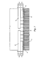
- the boiler nose 30 is used as a plenum for receiving overfire air and injecting the overfire air directly into the flue gases passing through the flue gas passage restriction 33.
- overfire air may be supplied directly into the cavity or plenum 32 within the boiler nose 30 for flow through injection ports 34 directly into the flue gas passage.
- the ports 34 are arrayed in the inclined wall portion of the boiler nose 30 and spaced one from the other between the opposite side walls 16 of the boiler. While the injection ports 34 are illustrated in the lower wall surface of the boiler nose inclined upwardly toward the restriction in the passage, it will be appreciated that the injection ports 34 may be disposed in the upper inclined surface of the boiler nose extending in a direction away from the restricted passage 33.
- one or more ducts are provided for introducing overfire air into the cavity or plenum within the boiler nose and additional port ducts are used to communicate the overfire air from the supply ducts to the injection ports.
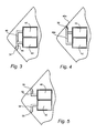
- the overfire air supply ducts may comprise upper and lower ducts 40 and 42 respectively which penetrate one or both side walls 44 of the boiler for reception in the cavity or plenum through the boiler nose 30.
- the boiler side wall as well as the nose 30 are formed with water tubes 35. As illustrated, the water tubes 35 in the side wall are separated to provide an entry opening for receiving the ducts 40 and 42 into the nose 30.
- Port ducts for example, the port ducts 44 and 46 ( Figure 3)respectively communicate between the upper and lower ducts 40 and 42 and injection ports 34 formed through the inclined walls of the boiler nose 30. Consequently as illustrated in Figure 3, overfire air received in the upper duct 40 flows through the port duct 46 to injection ports 34 arrayed along the inclined surface of the boiler nose 30. Similarly, overfire air is supplied through duct 42 via port ducts 44 to injection ports 34 also arrayed along the inclined portion of the boiler nose.
- the various port ducts 44 and 46 may be spaced one from the other along the boiler nose to provide overfire air into selected regions or zones of the restricted flue gas passage 33.
- the lower duct 42 may supply port ducts 44 located adjacent opposite ends of the boiler nose while the duct 40 supplies port ducts 46 and injection ports spaced intermediate the injection ports supplied with overfire air from the lower duct 42.
- the overfire air may be provided in selected zones along the boiler nose and also at different pressures, if desired.
- the injection ports 34 are arrayed along the lower wall of the boiler nose inclined in the direction of the vertical flow of the flue gases toward the restriction in the flue gas passage 33.
- the upper and lower ducts 40 and 42 supply overfire air to port ducts 44a and 46a for flow to injection ports 50 arrayed along the upper inclined surface of the boiler nose, i.e. along the surface of the boiler nose which inclines in the direction of the flue gas flow and away from the restricted passage 33.
- the upper and lower supply ducts 40 and 42 respectively supply overfire air through port ducts 52 and 54 to injection ports 56 and 58 along the respective upper and lower inclined surfaces of the boiler nose.
- overfire air supply ducts 60 and 62 may pass through the opposite side walls of the boiler terminating substantially medially of the furnace between those side walls.
- the ducts communicate with port ducts, not shown in this Figure, for supplying overfire air to injection ports along one or both of the inclined wall surfaces of the boiler nose similarly as described above.
- upper and lower overfire air supply ducts 40 and 42 respectively, penetrate the side walls of the boiler.
- the upper ducts 40 terminate generally medially of the boiler from the side walls while the lower ducts 42 terminate substantially medially between the termination of the upper duct and the side wall.
- the plenum or cavity of the nose may serve as the duct for the overfire air without the necessity of discrete ducts within the cavity or plenum.
- the overfire air flows directly from the cavity or plenum through the ports in the inclined surface(s) of the nose and into the flue gas. In all cases, the air penetration and mixing into the upwardly flowing flue gas stream is assured.
Landscapes
- Engineering & Computer Science (AREA)
- Chemical & Material Sciences (AREA)
- Combustion & Propulsion (AREA)
- Physics & Mathematics (AREA)
- Thermal Sciences (AREA)
- Mechanical Engineering (AREA)
- General Engineering & Computer Science (AREA)
- Air Supply (AREA)
- Combustion Of Fluid Fuel (AREA)
Applications Claiming Priority (2)
| Application Number | Priority Date | Filing Date | Title |
|---|---|---|---|
| US868847 | 2004-06-17 | ||
| US10/868,847 US7004086B2 (en) | 2004-06-17 | 2004-06-17 | Injection of overfire air through the upper furnace arch for penetration and mixing with flue gas |
Publications (2)
| Publication Number | Publication Date |
|---|---|
| EP1607680A1 true EP1607680A1 (de) | 2005-12-21 |
| EP1607680B1 EP1607680B1 (de) | 2013-03-27 |
Family
ID=34941636
Family Applications (1)
| Application Number | Title | Priority Date | Filing Date |
|---|---|---|---|
| EP05253579A Ceased EP1607680B1 (de) | 2004-06-17 | 2005-06-10 | Brennkammer mit Oberluftinjektion |
Country Status (4)
| Country | Link |
|---|---|
| US (1) | US7004086B2 (de) |
| EP (1) | EP1607680B1 (de) |
| JP (1) | JP2006003074A (de) |
| CN (2) | CN1710330A (de) |
Cited By (5)
| Publication number | Priority date | Publication date | Assignee | Title |
|---|---|---|---|---|
| NL1034043C2 (nl) * | 2007-06-27 | 2008-12-30 | Tetratube B V | Horizontale structuur in een ketel. |
| EP2213936A1 (de) * | 2008-11-10 | 2010-08-04 | Siemens Aktiengesellschaft | Durchlaufdampferzeuger |
| WO2011086233A1 (en) * | 2010-01-15 | 2011-07-21 | Foster Wheeler Energia Oy | Steam generation boiler |
| CN110319713A (zh) * | 2019-07-26 | 2019-10-11 | 中国电力工程顾问集团西北电力设计院有限公司 | 一种自然通风直接空冷和烟塔合一组合机组的排布结构 |
| EP4047272A1 (de) * | 2021-02-23 | 2022-08-24 | Doosan Lentjes GmbH | Verbrennungsanlage für festmaterial |
Families Citing this family (8)
| Publication number | Priority date | Publication date | Assignee | Title |
|---|---|---|---|---|
| US20080083356A1 (en) * | 2006-10-09 | 2008-04-10 | Roy Payne | HYBRID BOOSTED OVERFIRE AIR SYSTEM AND METHODS FOR NOx REDUCTION IN COMBUSTION GASES |
| US20090084346A1 (en) * | 2007-09-28 | 2009-04-02 | General Electric Company | Gas flow injector and method of injecting gas into a combustion system |
| JP5022204B2 (ja) * | 2007-12-17 | 2012-09-12 | 三菱重工業株式会社 | 舶用ボイラ構造 |
| US7775791B2 (en) | 2008-02-25 | 2010-08-17 | General Electric Company | Method and apparatus for staged combustion of air and fuel |
| US20100203461A1 (en) * | 2009-02-06 | 2010-08-12 | General Electric Company | Combustion systems and processes for burning fossil fuel with reduced emissions |
| US8302545B2 (en) * | 2009-02-20 | 2012-11-06 | General Electric Company | Systems for staged combustion of air and fuel |
| US8906301B2 (en) * | 2009-09-15 | 2014-12-09 | General Electric Company | Combustion control system and method using spatial feedback and acoustic forcings of jets |
| CN119778704B (zh) * | 2025-03-10 | 2025-07-11 | 克雷登热能设备(浙江)有限公司 | 一种饱和两用蒸汽锅炉及其烟道结构 |
Citations (4)
| Publication number | Priority date | Publication date | Assignee | Title |
|---|---|---|---|---|
| FR2645625A1 (fr) | 1989-04-07 | 1990-10-12 | Otv D | Procede pour le traitement de dechets menagers et chaudiere pour la mise en oeuvre de ce procede |
| EP0754907A2 (de) | 1995-07-18 | 1997-01-22 | BURMEISTER & WAIN ENERGI A/S | Verfahren zur Regelung der Verbrennung in einem Heizkessel mit schwingendem Rost |
| US5771817A (en) * | 1994-06-20 | 1998-06-30 | Kvaerner Pulping Ab | Recovery boiler |
| JP2001221406A (ja) * | 2000-02-04 | 2001-08-17 | Hitachi Ltd | ボイラとその改造方法 |
Family Cites Families (9)
| Publication number | Priority date | Publication date | Assignee | Title |
|---|---|---|---|---|
| JPS6036522B2 (ja) * | 1982-11-15 | 1985-08-21 | バブコツク日立株式会社 | ボイラ装置 |
| JPS60126507A (ja) * | 1983-12-09 | 1985-07-06 | Kawasaki Heavy Ind Ltd | 燃焼室 |
| CN2085028U (zh) * | 1990-04-04 | 1991-09-18 | 北京市光华木材厂 | 抛煤机锅炉高效消烟洗涤器 |
| SE502327C2 (sv) * | 1993-12-29 | 1995-10-02 | Kvaerner Pulping Tech | Sodapanna för förbränning av avlutar |
| CN2209273Y (zh) * | 1994-03-25 | 1995-10-04 | 刘家机 | 一种炉内消烟除尘节能装置 |
| CN2215661Y (zh) * | 1994-10-10 | 1995-12-20 | 刘雪华 | 一种抛喷煤锅炉 |
| JPH10232002A (ja) * | 1996-12-17 | 1998-09-02 | Babcock Hitachi Kk | ボイラ |
| JPH10205734A (ja) * | 1997-01-14 | 1998-08-04 | Takuma Co Ltd | ストーカ式燃焼炉における2次空気の供給方法 |
| CN2367908Y (zh) * | 1999-04-16 | 2000-03-08 | 陈宏春 | 垃圾焚烧炉 |
-
2004
- 2004-06-17 US US10/868,847 patent/US7004086B2/en not_active Expired - Lifetime
-
2005
- 2005-06-10 EP EP05253579A patent/EP1607680B1/de not_active Ceased
- 2005-06-16 JP JP2005176119A patent/JP2006003074A/ja active Pending
- 2005-06-17 CN CNA2005100785559A patent/CN1710330A/zh active Pending
- 2005-06-17 CN CN201410104255.2A patent/CN103822204A/zh active Pending
Patent Citations (4)
| Publication number | Priority date | Publication date | Assignee | Title |
|---|---|---|---|---|
| FR2645625A1 (fr) | 1989-04-07 | 1990-10-12 | Otv D | Procede pour le traitement de dechets menagers et chaudiere pour la mise en oeuvre de ce procede |
| US5771817A (en) * | 1994-06-20 | 1998-06-30 | Kvaerner Pulping Ab | Recovery boiler |
| EP0754907A2 (de) | 1995-07-18 | 1997-01-22 | BURMEISTER & WAIN ENERGI A/S | Verfahren zur Regelung der Verbrennung in einem Heizkessel mit schwingendem Rost |
| JP2001221406A (ja) * | 2000-02-04 | 2001-08-17 | Hitachi Ltd | ボイラとその改造方法 |
Non-Patent Citations (1)
| Title |
|---|
| PATENT ABSTRACTS OF JAPAN vol. 2000, no. 25 12 April 2001 (2001-04-12) * |
Cited By (11)
| Publication number | Priority date | Publication date | Assignee | Title |
|---|---|---|---|---|
| NL1034043C2 (nl) * | 2007-06-27 | 2008-12-30 | Tetratube B V | Horizontale structuur in een ketel. |
| EP2009354A1 (de) * | 2007-06-27 | 2008-12-31 | Tetra Tube B.V. | Horizontale Struktur in einem Kessel |
| EP2213936A1 (de) * | 2008-11-10 | 2010-08-04 | Siemens Aktiengesellschaft | Durchlaufdampferzeuger |
| WO2010052158A3 (de) * | 2008-11-10 | 2010-08-19 | Siemens Aktiengesellschaft | Durchlaufdampferzeuger |
| US8851023B2 (en) | 2008-11-10 | 2014-10-07 | Siemens Aktiengesellschaft | Continuous steam generator |
| WO2011086233A1 (en) * | 2010-01-15 | 2011-07-21 | Foster Wheeler Energia Oy | Steam generation boiler |
| CN102782406A (zh) * | 2010-01-15 | 2012-11-14 | 福斯特韦勒能源股份公司 | 蒸汽发生锅炉 |
| US8967088B2 (en) | 2010-01-15 | 2015-03-03 | Foster Wheeler Energia Oy | Steam generation boiler |
| CN110319713A (zh) * | 2019-07-26 | 2019-10-11 | 中国电力工程顾问集团西北电力设计院有限公司 | 一种自然通风直接空冷和烟塔合一组合机组的排布结构 |
| CN110319713B (zh) * | 2019-07-26 | 2024-02-06 | 中国电力工程顾问集团西北电力设计院有限公司 | 一种自然通风直接空冷和烟塔合一组合机组的排布结构 |
| EP4047272A1 (de) * | 2021-02-23 | 2022-08-24 | Doosan Lentjes GmbH | Verbrennungsanlage für festmaterial |
Also Published As
| Publication number | Publication date |
|---|---|
| CN103822204A (zh) | 2014-05-28 |
| JP2006003074A (ja) | 2006-01-05 |
| EP1607680B1 (de) | 2013-03-27 |
| US7004086B2 (en) | 2006-02-28 |
| CN1710330A (zh) | 2005-12-21 |
| US20050279262A1 (en) | 2005-12-22 |
Similar Documents
| Publication | Publication Date | Title |
|---|---|---|
| US7004086B2 (en) | Injection of overfire air through the upper furnace arch for penetration and mixing with flue gas | |
| US7670135B1 (en) | Burner and method for induction of flue gas | |
| US5823769A (en) | In-line method of burner firing and NOx emission control for glass melting | |
| CN101611263B (zh) | 燃气锅炉的燃烧器 | |
| KR100883796B1 (ko) | 린-리치 연소방식을 이용한 분젠버너 | |
| EP0612958A2 (de) | Verbrennungsverfahren und Kraftstoffbrennervorrichtung mit divergierenden Düse | |
| KR20130042516A (ko) | 코안다 가스 버너 장치 및 연소 방법 | |
| US5836257A (en) | Circulating fluidized bed furnace/reactor with an integral secondary air plenum | |
| CN108603659B (zh) | 低NOx燃烧器装置和方法 | |
| EP1505341A1 (de) | Kessel | |
| CN105378385A (zh) | 燃烧装置 | |
| CA1308964C (en) | Method and apparatus for improving fluid flow and gas mixing in boilers | |
| US4511325A (en) | System for the reduction of NOx emissions | |
| KR20100047197A (ko) | 고온 공기 연소 기술을 이용한 반응로 | |
| US6742463B2 (en) | Combustion air system for recovery boilers, burning spent liquors from pulping processes | |
| KR20100087365A (ko) | 선박용 보일러 구조 | |
| EP1467148B1 (de) | Luftsystem für einen Wirbelbettkessel | |
| EP1108951B1 (de) | Brenner mit gestufter Luft- und Brennstoffzufuhr | |
| FI118807B (fi) | Järjestelmä soodakattilan virtauskentän hallitsemiseksi | |
| US6409502B2 (en) | Gas burners for heating a gas flowing in a duct | |
| EP1729062A2 (de) | Dynamische Brennerrekonfiguration und Verbrennungsvorrichtung für Heizkessel und Prozesserhitzer | |
| KR101197880B1 (ko) | 연속가열로 | |
| CN212362003U (zh) | W火焰锅炉 | |
| US6979191B1 (en) | Combustion apparatus and method for radiating wall heating system | |
| EP3479021B1 (de) | Stationärer wirbelschichtofen |
Legal Events
| Date | Code | Title | Description |
|---|---|---|---|
| PUAI | Public reference made under article 153(3) epc to a published international application that has entered the european phase |
Free format text: ORIGINAL CODE: 0009012 |
|
| AK | Designated contracting states |
Kind code of ref document: A1 Designated state(s): AT BE BG CH CY CZ DE DK EE ES FI FR GB GR HU IE IS IT LI LT LU MC NL PL PT RO SE SI SK TR |
|
| AX | Request for extension of the european patent |
Extension state: AL BA HR LV MK YU |
|
| 17P | Request for examination filed |
Effective date: 20060621 |
|
| AKX | Designation fees paid |
Designated state(s): DE GB IT |
|
| 17Q | First examination report despatched |
Effective date: 20110822 |
|
| GRAP | Despatch of communication of intention to grant a patent |
Free format text: ORIGINAL CODE: EPIDOSNIGR1 |
|
| GRAS | Grant fee paid |
Free format text: ORIGINAL CODE: EPIDOSNIGR3 |
|
| GRAA | (expected) grant |
Free format text: ORIGINAL CODE: 0009210 |
|
| AK | Designated contracting states |
Kind code of ref document: B1 Designated state(s): DE GB IT |
|
| REG | Reference to a national code |
Ref country code: GB Ref legal event code: FG4D |
|
| REG | Reference to a national code |
Ref country code: DE Ref legal event code: R096 Ref document number: 602005038739 Country of ref document: DE Effective date: 20130523 |
|
| PLBE | No opposition filed within time limit |
Free format text: ORIGINAL CODE: 0009261 |
|
| STAA | Information on the status of an ep patent application or granted ep patent |
Free format text: STATUS: NO OPPOSITION FILED WITHIN TIME LIMIT |
|
| 26N | No opposition filed |
Effective date: 20140103 |
|
| REG | Reference to a national code |
Ref country code: DE Ref legal event code: R097 Ref document number: 602005038739 Country of ref document: DE Effective date: 20140103 |
|
| PGFP | Annual fee paid to national office [announced via postgrant information from national office to epo] |
Ref country code: DE Payment date: 20200519 Year of fee payment: 16 |
|
| PGFP | Annual fee paid to national office [announced via postgrant information from national office to epo] |
Ref country code: IT Payment date: 20200519 Year of fee payment: 16 Ref country code: GB Payment date: 20200525 Year of fee payment: 16 |
|
| REG | Reference to a national code |
Ref country code: DE Ref legal event code: R119 Ref document number: 602005038739 Country of ref document: DE |
|
| GBPC | Gb: european patent ceased through non-payment of renewal fee |
Effective date: 20210610 |
|
| PG25 | Lapsed in a contracting state [announced via postgrant information from national office to epo] |
Ref country code: GB Free format text: LAPSE BECAUSE OF NON-PAYMENT OF DUE FEES Effective date: 20210610 Ref country code: DE Free format text: LAPSE BECAUSE OF NON-PAYMENT OF DUE FEES Effective date: 20220101 |
|
| PG25 | Lapsed in a contracting state [announced via postgrant information from national office to epo] |
Ref country code: IT Free format text: LAPSE BECAUSE OF NON-PAYMENT OF DUE FEES Effective date: 20210610 |