EP1607849A2 - Support de touche pour dispositif de pointage et dispositif de pointage - Google Patents
Support de touche pour dispositif de pointage et dispositif de pointage Download PDFInfo
- Publication number
- EP1607849A2 EP1607849A2 EP05011431A EP05011431A EP1607849A2 EP 1607849 A2 EP1607849 A2 EP 1607849A2 EP 05011431 A EP05011431 A EP 05011431A EP 05011431 A EP05011431 A EP 05011431A EP 1607849 A2 EP1607849 A2 EP 1607849A2
- Authority
- EP
- European Patent Office
- Prior art keywords
- pointing device
- magnet
- support portion
- key top
- circuit board
- Prior art date
- Legal status (The legal status is an assumption and is not a legal conclusion. Google has not performed a legal analysis and makes no representation as to the accuracy of the status listed.)
- Withdrawn
Links
Images



Classifications
-
- G—PHYSICS
- G06—COMPUTING OR CALCULATING; COUNTING
- G06F—ELECTRIC DIGITAL DATA PROCESSING
- G06F3/00—Input arrangements for transferring data to be processed into a form capable of being handled by the computer; Output arrangements for transferring data from processing unit to output unit, e.g. interface arrangements
- G06F3/01—Input arrangements or combined input and output arrangements for interaction between user and computer
- G06F3/03—Arrangements for converting the position or the displacement of a member into a coded form
- G06F3/033—Pointing devices displaced or positioned by the user, e.g. mice, trackballs, pens or joysticks; Accessories therefor
- G06F3/0338—Pointing devices displaced or positioned by the user, e.g. mice, trackballs, pens or joysticks; Accessories therefor with detection of limited linear or angular displacement of an operating part of the device from a neutral position, e.g. isotonic or isometric joysticks
-
- H—ELECTRICITY
- H01—ELECTRIC ELEMENTS
- H01H—ELECTRIC SWITCHES; RELAYS; SELECTORS; EMERGENCY PROTECTIVE DEVICES
- H01H13/00—Switches having rectilinearly-movable operating part or parts adapted for pushing or pulling in one direction only, e.g. push-button switch
- H01H13/02—Details
- H01H13/26—Snap-action arrangements depending upon deformation of elastic members
Definitions
- the present invention relates to a pointing device utilized as an operating device for an electronic device such as a mobile phone, a PDA, or a game controller, and relates to a key sheet for the pointing device. More particularly, the present invention relates to a pointing device of a magnetic field detection type which detects a change in magnetic flux density resulting from movements made by a magnet, and relates to a key sheet for the pointing device.
- a pointing device of a magnetic field detection type which detects a change in magnetic flux density resulting from "a lateral movement" of a magnet such as a tilt or a horizontal displacement by means of a magnetic field sensor and utilizes the detected change as an input signal.
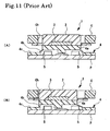
- a pointing device 1 shown in FIG. 11 includes a key top 2 exposed through a penetration hole Ch of a casing C of an electronic device such as a mobile phone, a magnet 3, a base sheet 4, and magnetic field sensors 5 such as Hall elements mounted on a printed circuit board P.
- the base sheet 4 is formed of a thick support portion 4a, a thin flexible portion 4b, and a fixation portion 4c for the printed circuit board P.
- the key top 2 and the magnet 3 are firmly fixed to the support portion 4a. As shown in FIGS.
- the support portion 4a may slide into contact with the magnetic field sensors 5 at the time of a lateral movement to a state shown in FIG. 11(B).
- a rupture may occur in the support portion 4a, or mounting conditions of the magnetic field sensors 5 with respect to the printed circuit board P may be adversely affected through sliding contact with the support portion 4a.
- the clearance between the support portion 4a and the front face of the printed circuit board P must be set large. But there is a limit to a reduction in thickness of the pointing device 1 and a demand for size reduction of electronic devices cannot be satisfied.
- the present invention has been made in view of the foregoing related arts. It is an object of the present invention to reduce a thickness of a pointing device.
- the present invention provides a key sheet for a pointing device in which a change in magnetic flux density, which occurs as a magnet laterally moves, is detected by at least one magnetic field sensor provided on a printed circuit board, the key sheet being characterized by including a base sheet made of a rubber-like elastic body including; a support portion for supporting a magnet; a flexible portion that is laterally deformable to expand and contract so that the support portion can be laterally moved; and a directional deformation portion formed in the flexible portion, for guiding and displacing a reverse face of the flexible portion away from a front face of a printed circuit board as the support portion laterally moves.
- the reverse face of the flexible portion is displaced while being guided away from the front face of the printed circuit board due to deformation of the directional deformation portion.
- the clearance between the reverse face of the flexible portion and the front face of the printed circuit board increases. Accordingly, even if the magnetic field sensor is mounted on the front face of the printed circuit board, it need not be mounted below the support portion. In this respect, a limit to the reduction in thickness in the foregoing related arts is overcome, and first of all, the pointing device is reduced in thickness. Even if the magnetic field sensor is mounted below the flexible portion, the clearance is increased by the directional deformation portion on a lateral movement where the flexible portion contracts as described above. Therefore, the flexible portion would not be ruptured through sliding contact with the magnetic field sensor.
- the flexible portion is not ruptured through sliding contact with the magnetic field sensor, so it is still impossible to prevent a rupture from occurring due to a deterioration resulting from excessive repetition of expansive deformation of the rubber-like elastic body constituting the base sheet.
- the flexible portion may be in contact with the magnetic field sensor.
- the directional deformation portion guides and displaces the reverse face of the flexible portion away from the front face of the printed circuit board.
- the directional deformation portion is formed as a mountain fold flexure portion protruding away from the front face of the printed circuit board.
- a recess groove opening downwards may be formed as the directional deformation portion on a side facing the printed circuit board so that the flexible portion is guided to be flexed away from the front face of the printed circuit board.
- the flexible portion of the present invention may be structured by forming at least one reverse face thereof as a face inclined upwards to the directional deformation portion side from the support portion side. Therefore, the flexible portion can be reliably prevented from sliding into contact with the magnetic field sensor when the support portion laterally moves.
- the flexible portion of the present invention may be structured by increasing thickness thereof from the directional deformation portion side to the support portion side. Therefore, the side of the support portion is thick and unlikely to deform, so the directional deformation portion can be reliably deformed.
- the magnet of the present invention may comprise one of an annular magnet and a plurality of magnet pieces that are disposed at annular positions.
- the magnet may be magnetized radially inwards and outwards. If the magnet is magnetized radially inwards and outwards, for example, if the annular magnet is magnetized such that its inner peripheral side serves as a south pole and its outer peripheral side serves as a north pole, the density of magnetic fluxes leaking outside can be reduced, and temperature characteristic can also be improved in comparison with a magnet that is magnetized in its thickness direction that is its upper side serves as a south pole and its lower side serves as a north pole, for example.
- the pointing device can be reduced in thickness.
- the magnetic field sensor to sense a magnetic field horizontally with respect to the printed circuit board, a change in magnetic flux caused by movements of the magnet can be sensed greatly.
- the magnet of the present invention may be constructed as a plastic magnet.
- the magnet is reduced in thickness, thereby achieving the pointing device reduced in thickness.
- the present invention is arranged such that the support portion has a magnet accommodating recess portion formed therein, and wherein the key sheet further comprises a key top for blocking the magnet accommodating recess portion, the key top being mounted on a front face of the support portion.
- the key top can reliably prevent the magnet from falling off from the magnet accommodating recess portion.
- the magnet accommodating recess portion is formed not in the key top but in the support portion of the base sheet, a bottom face of the key top can be constructed as a flat face, and a printing layer for displaying letters, numerals, symbols, and the like can be formed in the bottom face.
- the support portion and the key top may be firmly fixed to each other by interposing an adhesive layer therebetween.
- the present invention may be arranged such that the base sheet is formed of a translucent rubber-like elastic body, that the key top is formed of a translucent resin having a main body portion and a flange portion provided at a lower end of the main body portion, and that the magnet accommodating recess portion is formed in the support portion at a position facing the flange portion.
- the base sheet is formed of a translucent rubber-like elastic body
- the key top is formed of a translucent resin having a main body portion and a flange portion provided at a lower end of the main body portion
- the magnet accommodating recess portion is formed in the support portion at a position facing the flange portion.
- the present invention may be arranged such that the support portion is formed as a thin support portion having a penetration hole, that a lower key top made of a hard resin and an upper key top, which sandwich a front face and a reverse face of the support portion by firm fixation through the penetration hole, are provided, and that a magnet accommodating recess portion is formed in the lower key top.
- a portion facing the front face of the printed circuit board is not as the support portion of the base sheet made of the rubber-like elastic body but is the lower key top made of the hard resin.
- the present invention provides a pointing device, characterized by including: a magnet; a base sheet made of a rubber-like elastic body and having a flexible portion that is laterally deformable to expand and contract so that a support portion for supporting the magnet can be laterally moved; and at least one magnetic field sensor that is provided on a printed circuit board and detects a change in magnetic flux density caused by the magnet moving laterally together with the support portion, wherein the base sheet has a directional deformation portion formed in the flexible portion, for guiding and displacing a reverse face of the flexible portion away from a front face of the printed circuit board as the support portion laterally moves.
- the clearance between the reverse face of the flexible portion and the front face of the printed circuit board is increased due to deformation of the directional deformation portion in the flexible portion of the base sheet. Therefore, even if the magnetic field sensor is mounted to the front face of the printed circuit board, it need not be mounted below the support portion, thereby attaining the pointing device reduced in thickness. Also, even if the magnetic field sensor is mounted below the flexible portion, the flexible portion is prevented from rupturing through sliding contact with the magnetic field sensor, due to an increase in clearance on a lateral movement where the flexible portion contracts.
- the present invention is arranged such that the magnetic field sensor is provided on the front face of the printed circuit board at a position facing the directional deformation portion.
- the magnetic field sensor is located not below the support portion but below the flexible portion, and the directional deformation portion is located above facing the magnetic field sensor. Therefore, while the magnetic field sensor is mounted on the front face of the printed circuit board, it is possible to attain the pointing device reduced in thickness without causing the base sheet to rupture through sliding contact.
- the present invention is arranged such that the internal light source for light radiation is provided on the front face of the printed circuit board at a position facing the directional deformation portion.
- the internal light source for light radiation is located not below the support portion but below the flexible portion, and the directional deformation portion is located above facing the internal light source for light radiation. Therefore, while the internal light source for light radiation is mounted on the front face of the printed circuit board, it is possible to attain the pointing device reduced in thickness and endowed with a light radiation function without causing the base sheet to rupture through sliding contact.
- the respective components of the pointing device according to the present invention namely, the base sheet, the support portion for the base sheet, the magnet, and the key top with a key sheet for the pointing device according to the present invention and its components, the same operation and effect as those of the key sheet and its components can be achieved.
- the directional deformation portion is formed in the flexible portion of the base sheet in the key sheet, which leads to a reduction in thickness of the pointing device as a whole.
- the pointing device can also be installed in a portable device such as a mobile phone or a PDA, which has been ardently demanded to be reduced in size and thickness, and various input operations including the scrolling on a display screen and the entry of coordinates can be realized.
- a pointing device 10 of this embodiment is composed of a central key top 11, an outer peripheral key top 12, a base sheet 13, an annular magnet 14, and magnetic field sensors 5 mounted on a printed circuit board P.
- a key sheet is constructed of the remaining construction except the magnetic field sensors 5.
- the central key top 11 is formed of a columnar main body portion 11a and a circular flange portion 11b.
- the central key top 11 being made of a hard resin including an elastomer is within the scope of the invention.
- the central key top 11 being of a metal or being of another suitable material is also within the scope of the invention.
- the outer peripheral key top 12 is circularly formed with a penetration hole 12a for exposing the central key top 11.
- the outer peripheral key top 12 being made of a hard resin including an elastomer is within the scope of the invention.
- the outer peripheral key top 12 being of a metal or being of another suitable material is also within the scope of the invention.
- the central key top 11 is movable in all directions by 360° within an extending range of the penetration hole 12a.
- the central key top 11 is firmly fixed to the base sheet 13 via an adhesive layer 15.
- the outer peripheral key top 12 is also firmly fixed to the base sheet 13 via an adhesive layer (not shown).
- the base sheet 13 is formed of a thick columnar support portion 13a supporting the central key top 11 and the annular magnet 14 and a flexible portion 13b surrounding an outer periphery of the support portion 13a.
- a pressing element 13c is formed at a center of the support portion 13a.
- the pressing element 13c buckles a contact belleville spring Pi on the printed circuit board P and thus enables switch input.
- a magnet accommodating recess portion 13d for the annular magnet 14 is formed in the support portion 13a.
- the magnet accommodating recess portion 13d is sealed by the flange portion 11b of the central key top 11 via the adhesive layer 15, whereby the annular magnet 14 is prevented from falling off.
- the flexible portion 13b is composed of an upward inclined face portion 13e, an undulated bellows portion 13f, and a flat portion 13g, which are arranged in this order from an inner periphery side.
- the upward inclined face portion 13e is formed to be thick on its root side for the support portion 13a and made thinner as it spreads outwards. For this reason, the upward inclined face portion 13e is relatively hard to deform on its thick root side and is more likely to deform as it spreads outwards. As the upward inclined face portion 13e spreads outwards from its root side, it is inclined upwards and the distance from the printed circuit board P increases. Therefore, the upward inclined face portion 13e is spaced apart from the magnetic field sensors 5 as in a state shown in FIG. 1.
- the bellows portion 13f is formed by being flexed outwards in a multistage manner from an outer peripheral upper end of the inclined face portion 13e. Owing to this multistage flexure, the bellows portion 13f can expand and contract in accordance with lateral movements of the central key top 11. A force causing the laterally moved central key top 11 to return to its initial position is mainly given by the bellows portion 13f.
- the flat portion 13g is formed horizontally from a lower end of the bellows portion 13f. Pressing elements 13h are formed in the flat portion 13g as well. When the outer peripheral key top 12 is operated to be pressed, the pressing elements 13h buckle contact belleville springs Po and thus enable switch input.
- a plastic magnet 14 which is obtained by filling a binder resin with a powder from the group comprising an Alnico magnet, a ferrite magnet, a Sm-Co magnet, a Nd-Fe-B magnet, or the like is utilized as the annular magnet 14. Accordingly, the annular magnet 14 is thin and contributes toward reducing the thickness of the entire pointing device 10. Further, the magnetic field sensors 5, which detect the magnetic flux density whose direction coincides with magnetized direction of the magnet, is preferable. As shown in FIG 2, the annular magnet 14 is magnetized in its outer peripheral portion as a north pole and in its inner peripheral portion as a south pole.
- the annular magnet 14 Since the annular magnet 14 is thus magnetized radially inwards and outwards, the density of magnetic fluxes leaking outside can be reduced in comparison with a case where the annular magnet 14 is magnetized in its thickness direction. Further, since the direction in which the annular magnet 14 is magnetized coincides with the moving direction of the laterally moved central key top 11, the accuracy in detecting magnetic flux densities in the magnetic field sensors 5 can also be enhanced. Furthermore, the magnetic characteristic of the annular magnet 14 in a high temperature range can be stabilized.
- Hall elements Hall integrated circuits (ICs), magnetoresistive elements (MR), magnetoresistive ICs (MRICs), and the like can be utilized as the magnetic field sensors 5.
- the magnetic field sensors 5 are disposed inside the contact belleville springs Po, which are arranged at upper, lower, left, and right positions respectively.
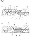
- the upward inclined face portion 13e and the bellows portion 13f are formed in the flexible portion 13b of the base sheet 11.
- the joint part between the upward inclined face portion 13e and the bellows portion 13f functions to produce a mountain fold flexure portion 13i, which is "a directional deformation portion" protruding away from a front face of the printed circuit board P.
- the support portion 13a and the flexible portion 13b is also laterally moved.
- the flexible portion 13b is guided and displaced away from the front face of the printed circuit board P in response to diagonally upward deformation in the mountain fold flexure portion 13i.
- the pointing device 10 can be reduced in thickness. Even if the magnetic field sensors 5 are mounted to the printed circuit board P below the flexible portion 13b, the clearance between the flexible portion 13b and the printed circuit board P is increased, and the flexible portion 13b can be prevented from sliding into contact with the magnetic field sensors 5, so that a rupture resulting from sliding contact can be obviated. As a result, the pointing device 10 can also be installed in a portable device such as a mobile phone or a PDA, which has been ardently demanded to be reduced in size and thickness, and diversified input operations including the scrolling on a display screen and the entry of coordinates, and the like can be realized.
- a portable device such as a mobile phone or a PDA
- the inclined face portion 13e of the flexible portion 13b deforming as described above is unlikely to deform on the thick root side for the support portion 13a and is more likely to deform as it spreads outwards.
- the inclined face portion 13e is prevented from unexpectedly deforming in a buckling manner from the root side and can be reliably guided and displaced with respect to the flexible portion 13b.
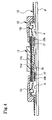
- the pointing device 10 according to this embodiment is different from the pointing device 10 according to the first embodiment in that a construction for realizing a light radiation function is added to the central key top 11.
- a first specific difference is that the central key top 11 is made of a transparent hard resin.
- a second specific difference is that the adhesive layer 15 is made of a translucent adhesive.
- a third specific difference is that the base sheet 12 is made of a translucent rubber-like elastic body.
- a fourth specific difference is that a drawn-out character printed layer 11c representing letters, numbers, symbols, or the like and a colored layer 11d including a white color and a metallic color to fill a drawn-out character portion of the drawn-out character printed layer 11c are formed on a bottom face of the central key top 11.
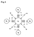
- a fifth specific difference is that the printed circuit board P is provided with internal light sources 16 for light radiation such as LED's as shown in FIG. 5.
- a sixth specific difference is that a plurality of magnet pieces 17 are arranged facing the magnetic field sensors 5 respectively as shown in FIG. 5 unlike the annular magnet 14 of the first embodiment and that circumferentially separated magnet accommodating recess portions 13k corresponding to the magnet pieces 17 respectively are formed in the base sheet 13.
- light from the internal light sources 16 can be radiated through the base sheet 13, the adhesive layer 15, the colored layer 11d, the drawn-out character printed layer 11c, and the central key top 11.
- the magnet pieces 17 are separated from one another, unlike the endless annular magnet 14 of the first embodiment. Therefore, as indicated by arrows in FIG. 5, spaces between the adjacent magnet pieces 17 on the base sheet 13 can be used as light paths. Thus, bright radiation of light is made possible.
- the internal light sources 16 are disposed at the same circumferential positions as the magnetic field sensors 5 respectively. Thus, when the central key top 11 laterally moves, the flexible portion 13b is prevented from rupturing through sliding contact with the internal light sources 16.
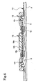
- FIG. 6 This embodiment is identical in construction to the first embodiment except in that a central key top 18 is different in construction from that of the pointing device 10 of the first embodiment.
- the central key top 18 of the third embodiment is obtained by molding a main body portion 18b made of a hard resin integrally with a resin film 18a.
- the central key top 18, which is a key top integrated with a film is advantageous in that the thickness of a flange portion 18c of the resin film 18a can be made equal to or smaller than 0.3 mm and a further reduction in thickness can be achieved. Besides, despite a reduction in thickness, no inconvenience such as breakage of the flange portion 18c results.
- the pointing device of this embodiment is different from the pointing device 10 of the first embodiment in that the annular magnet 14 is molded integrally with a flange portion 19a of a central key top 19. According to this construction, the central key top 19 and the annular magnet 14 constitute a single molded body. In a process of adhesion to the base sheet 13, therefore, the annular magnet 14 is made to function as a positioning protrusion and is accommodated in the magnet accommodating recess portion 13d, whereby positioning accuracy can be enhanced. This construction can also contribute toward achieving a further reduction in thickness corresponding to the thickness of the flange portion 19a.
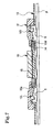
- FIG. 8 In this embodiment, a central key top 20 and a base sheet 21 are different from those of the pointing device 10 of the first embodiment.
- a support portion 21a is formed thinly with a penetration hole 21b, and an inclined face portion 21d in a flexible portion 21c is formed thinly with an equal thickness.
- the central key top 20 of this embodiment is composed of an upper key top 20a and a lower key top 20b, which sandwich the thin support portion 21 a from its front and reverse sides and are both made of a hard resin.
- a magnet accommodating recess portion 20c for the annular magnet 14 is formed in the lower key top 20b.
- a portion that faces the printed circuit board P is not, for example, the base sheet 13 made of the rubber-like elastic body as in the case of the first embodiment, but the lower key top 20b made of the hard resin.
- the central key top 20 slides into contact with the printed circuit board P in moving laterally, it is possible to eliminate such an inconvenience that the annular magnet 14 falls off due to a rupture of the accommodation recess 20c.
- a pressing element 20d of the lower key top 20b slides into contact with the metal contact belleville spring Pi, which leads to an advantage in performing smooth lateral movements.
- the pressing element 20d is made of the hard resin having a smaller friction coefficient than that of the rubber-like elastic body.
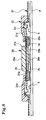
- a base sheet 22 of this embodiment has a construction different from that of the base sheet 13 of the first embodiment.
- a flexible portion 22a of the base sheet 22 is composed of a V-shaped flexure portion 22b having a V-shaped cross section, an inner flat portion 22c, and an outer flat portion 22d.
- a boundary portion 22e across which the V-shaped flexure portion 22b and the inner flat portion 22c continuously extend from each other functions as "the directional deformation portion". More specifically, when the central key top 11 is laterally moved, the V-shaped flexure portion 22b deforms in a crushing manner while being urged by a support portion 22f.
- the boundary portion 22e deforms upwards in this process, whereby a reverse face of the flexible portion 22a is guided and displaced away from the front face of the printed circuit board P. This also makes it possible to achieve the same operation and effect as those produced by the mountain fold flexure portion 13i of the first embodiment.
- operating protrusions corresponding to the central key top 11 and the outer peripheral key top 12 may be formed on the base sheet 13.
- the outer peripheral key top 12 may be circumferentially divided.
- a pointing device having only the central key top 11, dispensing with the outer peripheral key top 12, can also be constructed.
- the pointing device may be so constructed as to enable an input operation in all directions of 360° or in a specific direction, and the number and arrangement of the magnetic field sensors 5 may be changed accordingly.
- the construction specific to each of them can also be applied to the other ones.
- the drawn-out character printed layer 11c and the colored layer 11d of the second embodiment may also be applied to any other embodiment.
- the drawn-out character printed layer 11c may be replaced with a character printed layer and a colored layer.
- thermosetting elastomer such as silicone rubber or a thermoplastic elastomer such as a styrene-based substance
- a thermoplastic elastomer such as silicone rubber
- a thermoplastic resin such as a styrene-based substance
- integral molding is made possible by co-injection molding, without requiring an adhesion process, and ensuring a great fixing strength.
- the annular magnet 14 is formed of a plastic magnet.
- other types of magnet can be employed as well.
- the magnetic field sensors 5 are disposed between the contact belleville spring Pi and the contact belleville springs Po respectively.
- the magnetic field sensors 5 are offset by 45° around the contact belleville spring Pi, the magnetic field sensors 5 can be disposed among the contact belleville springs Po respectively, thereby making it possible to attain reduction in size.
- the magnetic field sensors 5 and the internal light sources 16 can also be offset by 30° around the contact belleville spring Pi to be disposed among the contact belleville springs Po respectively. In this case, it is appropriate that the magnet pieces 17 are disposed to positions facing the magnetic field sensors 5 respectively.
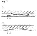
- the pressing element (indicated by 13c in FIG. 1) is formed as the rubber-like elastic body as a whole.
- FIG. 10 shows an example in which a pressing element 23 is provided with a leading end portion 23a made of a hard resin.
- FIG. 10(B) shows an example in which a pressing element 24 made of a hard resin is provided on the reverse face of the base sheet.
- a resin film Pf is firmly fixed through attachment or adhesion in such a manner as to cover the metal contact belleville spring Pi.
- a resin film made of a fluorocarbon resin, a polyamide resin, or the like, which exhibits abrasion resistance and has a low friction coefficient, may be utilized as the resin film Pf.
- the central key top 11 is endowed with the light radiation function. It is also possible to adopt a construction in which the outer peripheral key top 12 is made of a translucent resin and endowed with the light radiation function, through which light from the internal light sources 16 can be radiated.
- the resin film 18a is formed integrally with upper and lateral faces of the main body portion 18b.
- a resin film that is greater in width by a width of the flange portion may be formed integrally with a bottom face of the main body portion 18b.
Landscapes
- Engineering & Computer Science (AREA)
- General Engineering & Computer Science (AREA)
- Theoretical Computer Science (AREA)
- Human Computer Interaction (AREA)
- Physics & Mathematics (AREA)
- General Physics & Mathematics (AREA)
- Switches With Compound Operations (AREA)
- Switches That Are Operated By Magnetic Or Electric Fields (AREA)
- Telephone Set Structure (AREA)
- Switch Cases, Indication, And Locking (AREA)
- Push-Button Switches (AREA)
Applications Claiming Priority (2)
| Application Number | Priority Date | Filing Date | Title |
|---|---|---|---|
| JP2004163736A JP4495525B2 (ja) | 2004-06-01 | 2004-06-01 | ポインティングデバイス用のキーシート及びポインティングデバイス |
| JP2004163736 | 2004-06-01 |
Publications (2)
| Publication Number | Publication Date |
|---|---|
| EP1607849A2 true EP1607849A2 (fr) | 2005-12-21 |
| EP1607849A3 EP1607849A3 (fr) | 2012-01-25 |
Family
ID=35116132
Family Applications (1)
| Application Number | Title | Priority Date | Filing Date |
|---|---|---|---|
| EP05011431A Withdrawn EP1607849A3 (fr) | 2004-06-01 | 2005-05-27 | Support de touche pour dispositif de pointage et dispositif de pointage |
Country Status (5)
| Country | Link |
|---|---|
| US (1) | US7508376B2 (fr) |
| EP (1) | EP1607849A3 (fr) |
| JP (1) | JP4495525B2 (fr) |
| KR (1) | KR101118069B1 (fr) |
| CN (1) | CN100378890C (fr) |
Cited By (1)
| Publication number | Priority date | Publication date | Assignee | Title |
|---|---|---|---|---|
| EP2420735A1 (fr) * | 2010-08-20 | 2012-02-22 | BSH Bosch und Siemens Hausgeräte GmbH | Dispositif de commande pour un appareil ménager doté d'un dispositif d'alimentation en énergie et appareil ménager destiné à la préparation d'aliments à l'aide d'un tel dispositif de commande |
Families Citing this family (36)
| Publication number | Priority date | Publication date | Assignee | Title |
|---|---|---|---|---|
| JP4561394B2 (ja) * | 2005-02-17 | 2010-10-13 | オムロン株式会社 | 操作入力装置およびこれを用いた電子機器 |
| JP4584782B2 (ja) * | 2005-06-21 | 2010-11-24 | 旭化成エレクトロニクス株式会社 | ポインティングデバイスおよびポインティングデバイス用キーシート |
| KR100789725B1 (ko) * | 2006-05-15 | 2008-01-02 | 삼성전기주식회사 | 입력장치 |
| JP4605474B2 (ja) * | 2006-06-06 | 2011-01-05 | サンアロー株式会社 | 多方向入力装置 |
| KR100857166B1 (ko) * | 2006-11-29 | 2008-09-05 | 삼성전기주식회사 | 입력장치 및 이를 구비한 휴대 단말기 |
| KR100783470B1 (ko) * | 2006-11-29 | 2007-12-07 | 삼성전기주식회사 | 모바일 기기 |
| KR100783469B1 (ko) * | 2006-11-29 | 2007-12-07 | 삼성전기주식회사 | 모바일 기기 |
| KR100862950B1 (ko) * | 2007-02-14 | 2008-10-15 | 주식회사 이노칩테크놀로지 | 포인팅 장치 및 이를 갖는 휴대용 단말기 |
| TW200842666A (en) * | 2007-04-26 | 2008-11-01 | Distech Technology Co Ltd | Direction control device |
| JP2010533336A (ja) * | 2007-07-11 | 2010-10-21 | ユイ・ジン・オ | 指の動作感知を利用したデータ入力装置およびこれを利用した入力変換方法 |
| WO2009063799A1 (fr) * | 2007-11-12 | 2009-05-22 | Alps Electric Co., Ltd. | Dispositif d'entrée |
| KR100931071B1 (ko) * | 2008-04-14 | 2009-12-10 | 주식회사 이노칩테크놀로지 | 전자 장치 및 이의 아이콘 활성화 방법 |
| JP5098928B2 (ja) * | 2008-09-26 | 2012-12-12 | オムロン株式会社 | 入力装置およびこれを用いた電子機器 |
| JP2010114010A (ja) * | 2008-11-10 | 2010-05-20 | Shin Etsu Polymer Co Ltd | 携帯機器の照明構造 |
| TWM360436U (en) * | 2009-01-12 | 2009-07-01 | Speed Tech Corp | Structure of low profile multi-directional key |
| KR101022406B1 (ko) | 2009-01-29 | 2011-03-15 | 주식회사 이노칩테크놀로지 | 포인팅 장치 및 이를 갖는 전자 장치 |
| JP5267504B2 (ja) * | 2009-05-19 | 2013-08-21 | ミツミ電機株式会社 | 操作入力装置及び操作入力検出装置 |
| JP5356165B2 (ja) * | 2009-09-10 | 2013-12-04 | 信越ポリマー株式会社 | ポインティングデバイス |
| JP2012138167A (ja) * | 2009-09-30 | 2012-07-19 | Nec Corp | アナログポインティングキー構造 |
| CN102044371A (zh) * | 2009-10-19 | 2011-05-04 | 英业达股份有限公司 | 方向控制装置 |
| JP5440284B2 (ja) * | 2010-03-12 | 2014-03-12 | 日本電気株式会社 | アナログポインティングキー構造 |
| DE102010003292A1 (de) * | 2010-03-25 | 2011-09-29 | Fraunhofer-Gesellschaft zur Förderung der angewandten Forschung e.V. | Sensoranordnung und Verfahren zum Ermitteln einer Magnetisierungseinrichtung eines Gebermagneten |
| JP2012027786A (ja) * | 2010-07-26 | 2012-02-09 | Omron Corp | 入力装置および電子機器 |
| CN103140821B (zh) * | 2010-08-30 | 2016-02-10 | 日本电气株式会社 | 输入装置和配置有输入装置的电子设备 |
| KR20120049630A (ko) * | 2010-11-09 | 2012-05-17 | 주식회사 이노칩테크놀로지 | 다방향 입력 장치 |
| US9569002B2 (en) | 2010-12-17 | 2017-02-14 | Blackberry Limited | Portable electronic device having a sensor arrangement for gesture recognition |
| CA2837602A1 (fr) * | 2011-06-02 | 2012-12-06 | Nonin Medical, Inc. | Surveillance d'activite uterine a domicile |
| CN103187195A (zh) * | 2011-12-27 | 2013-07-03 | 名硕电脑(苏州)有限公司 | 磁性分离式按键及其键盘 |
| KR101584537B1 (ko) * | 2014-06-23 | 2016-01-22 | 엘지전자 주식회사 | 키 모듈 및 이를 구비하는 이동 단말기 |
| JP2015043344A (ja) * | 2014-12-02 | 2015-03-05 | レノボ・イノベーションズ・リミテッド(香港) | アナログポインティングキー構造 |
| JP6784518B2 (ja) * | 2016-06-10 | 2020-11-11 | 株式会社ソニー・インタラクティブエンタテインメント | 操作デバイス |
| US20180068145A1 (en) * | 2016-09-07 | 2018-03-08 | Hand Held Products, Inc. | Smart scan peripheral |
| TWI702626B (zh) * | 2018-03-30 | 2020-08-21 | 英屬開曼群島商康而富控股股份有限公司 | 具有較佳按壓手感的觸控按鍵 |
| JP6529017B1 (ja) * | 2018-05-23 | 2019-06-12 | 株式会社オリンピア | 遊技機 |
| WO2022131078A1 (fr) | 2020-12-14 | 2022-06-23 | 旭化成エレクトロニクス株式会社 | Dispositif d'entrée, dispositif de commande et procédé de détection d'erreur |
| TWI815275B (zh) * | 2022-01-13 | 2023-09-11 | 華碩電腦股份有限公司 | 手持式電子裝置 |
Family Cites Families (24)
| Publication number | Priority date | Publication date | Assignee | Title |
|---|---|---|---|---|
| JP2953775B2 (ja) | 1990-11-07 | 1999-09-27 | 富士通株式会社 | ポインティング制御装置 |
| JPH07117876B2 (ja) * | 1990-09-18 | 1995-12-18 | 富士通株式会社 | ポインティング制御装置 |
| JPH0635599A (ja) | 1992-07-14 | 1994-02-10 | Fujitsu Ltd | ポインティングデバイス |
| JPH06318134A (ja) * | 1994-03-15 | 1994-11-15 | Les-Ben:Kk | データ入力装置 |
| JPH07262879A (ja) * | 1994-03-23 | 1995-10-13 | Aiwa Co Ltd | スライド式スイッチ |
| JPH08185257A (ja) | 1994-10-31 | 1996-07-16 | Matsushita Electric Ind Co Ltd | 座標入力装置 |
| JPH08152961A (ja) | 1994-11-30 | 1996-06-11 | Fujitsu Ltd | ポインティングデバイス |
| JPH0934644A (ja) | 1995-07-21 | 1997-02-07 | Oki Electric Ind Co Ltd | ポインティングデバイス |
| JP3428255B2 (ja) | 1995-10-30 | 2003-07-22 | シャープ株式会社 | コンピュータ等の入力装置 |
| US5714980A (en) * | 1995-10-31 | 1998-02-03 | Mitsumi Electric Co., Ltd. | Pointing device |
| JP2000235822A (ja) * | 1999-02-15 | 2000-08-29 | Snk Corp | 多方向スイッチ装置及びこの多方向スイッチを用いた携帯用電子機器 |
| JP3828676B2 (ja) * | 1999-03-23 | 2006-10-04 | ホシデン株式会社 | ポインティング装置 |
| JP2001228967A (ja) * | 2000-02-17 | 2001-08-24 | Polymatech Co Ltd | ポインティングデバイス |
| GB2367346B (en) * | 2000-09-28 | 2004-07-14 | Nokia Mobile Phones Ltd | Control device |
| JP4121730B2 (ja) * | 2001-01-19 | 2008-07-23 | 富士通コンポーネント株式会社 | ポインティングデバイス及び携帯型情報機器 |
| JP4559706B2 (ja) | 2001-04-19 | 2010-10-13 | 旭化成エレクトロニクス株式会社 | ポインティングデバイス |
| JP4100897B2 (ja) * | 2001-11-28 | 2008-06-11 | 松下電器産業株式会社 | 多方向操作スイッチおよびその製造方法 |
| JP4105432B2 (ja) * | 2001-12-21 | 2008-06-25 | アルプス電気株式会社 | 多方向入力装置 |
| DE10212929A1 (de) * | 2002-03-19 | 2003-10-02 | Ego Elektro Geraetebau Gmbh | Bedienvorrichtung für ein Elektrogerät |
| JP4175007B2 (ja) * | 2002-03-22 | 2008-11-05 | 松下電器産業株式会社 | 回転操作型入力装置 |
| JP4147839B2 (ja) * | 2002-06-26 | 2008-09-10 | ポリマテック株式会社 | スライド式多方向入力キー |
| JP4108401B2 (ja) | 2002-07-26 | 2008-06-25 | 日本電気株式会社 | 入力装置及び移動端末 |
| JP4612361B2 (ja) * | 2004-08-31 | 2011-01-12 | ポリマテック株式会社 | キースイッチ |
| JP4584782B2 (ja) * | 2005-06-21 | 2010-11-24 | 旭化成エレクトロニクス株式会社 | ポインティングデバイスおよびポインティングデバイス用キーシート |
-
2004
- 2004-06-01 JP JP2004163736A patent/JP4495525B2/ja not_active Expired - Fee Related
-
2005
- 2005-05-27 US US11/138,436 patent/US7508376B2/en not_active Expired - Fee Related
- 2005-05-27 EP EP05011431A patent/EP1607849A3/fr not_active Withdrawn
- 2005-05-31 CN CNB2005100743128A patent/CN100378890C/zh not_active Expired - Fee Related
- 2005-06-01 KR KR1020050046879A patent/KR101118069B1/ko not_active Expired - Fee Related
Cited By (1)
| Publication number | Priority date | Publication date | Assignee | Title |
|---|---|---|---|---|
| EP2420735A1 (fr) * | 2010-08-20 | 2012-02-22 | BSH Bosch und Siemens Hausgeräte GmbH | Dispositif de commande pour un appareil ménager doté d'un dispositif d'alimentation en énergie et appareil ménager destiné à la préparation d'aliments à l'aide d'un tel dispositif de commande |
Also Published As
| Publication number | Publication date |
|---|---|
| JP2005347042A (ja) | 2005-12-15 |
| CN1705056A (zh) | 2005-12-07 |
| EP1607849A3 (fr) | 2012-01-25 |
| KR20060046385A (ko) | 2006-05-17 |
| US7508376B2 (en) | 2009-03-24 |
| KR101118069B1 (ko) | 2012-04-12 |
| US20050264530A1 (en) | 2005-12-01 |
| CN100378890C (zh) | 2008-04-02 |
| JP4495525B2 (ja) | 2010-07-07 |
Similar Documents
| Publication | Publication Date | Title |
|---|---|---|
| US7508376B2 (en) | Key sheet for pointing device and pointing device | |
| US7262374B2 (en) | Pointing device and key sheet for pointing device | |
| KR101070484B1 (ko) | 입력 장치 및 이것을 이용한 전자 기기 | |
| US8072425B2 (en) | Key sheet for a pointing device and pointing device | |
| JP4944486B2 (ja) | スライドパッド部材 | |
| EP2023233A1 (fr) | Dispositif d'entrée | |
| JP2004062447A (ja) | 入力装置及び移動端末 | |
| CN101075505B (zh) | 输入装置 | |
| US20110120849A1 (en) | Operation input device and electronic device using the same | |
| US10824252B1 (en) | Touchpad module | |
| KR20010039294A (ko) | 통신기용 키패드 | |
| JP5262254B2 (ja) | アナログポインティングキー構造 | |
| US20080125193A1 (en) | Input apparatus and mobile device having the same | |
| US8803016B2 (en) | Dome sheet structure including light guide film and mobile communication terminal including the dome sheet structure | |
| US8536965B2 (en) | Analog pointing key structure | |
| KR101085291B1 (ko) | 조작 입력 장치 | |
| WO2016002675A1 (fr) | Module de commutateur, dispositif électronique et procédé de fabrication de dispositif électronique | |
| JP4746447B2 (ja) | スライド操作キーシート | |
| CN102326222A (zh) | 多方向输入装置以及使用该装置的电子设备 | |
| JP2012104311A (ja) | ポインティングデバイス用キーシート | |
| JP2007250289A (ja) | 端末装置 |
Legal Events
| Date | Code | Title | Description |
|---|---|---|---|
| PUAI | Public reference made under article 153(3) epc to a published international application that has entered the european phase |
Free format text: ORIGINAL CODE: 0009012 |
|
| AK | Designated contracting states |
Kind code of ref document: A2 Designated state(s): AT BE BG CH CY CZ DE DK EE ES FI FR GB GR HU IE IS IT LI LT LU MC NL PL PT RO SE SI SK TR |
|
| AX | Request for extension of the european patent |
Extension state: AL BA HR LV MK YU |
|
| RAP1 | Party data changed (applicant data changed or rights of an application transferred) |
Owner name: POLYMATECH CO., LTD. Owner name: ASAHI KASEI EMD CORPORATION |
|
| PUAL | Search report despatched |
Free format text: ORIGINAL CODE: 0009013 |
|
| AK | Designated contracting states |
Kind code of ref document: A3 Designated state(s): AT BE BG CH CY CZ DE DK EE ES FI FR GB GR HU IE IS IT LI LT LU MC NL PL PT RO SE SI SK TR |
|
| AX | Request for extension of the european patent |
Extension state: AL BA HR LV MK YU |
|
| RIC1 | Information provided on ipc code assigned before grant |
Ipc: G06F 3/033 20060101AFI20111221BHEP |
|
| 17P | Request for examination filed |
Effective date: 20120420 |
|
| AKX | Designation fees paid |
Designated state(s): DE |
|
| STAA | Information on the status of an ep patent application or granted ep patent |
Free format text: STATUS: THE APPLICATION IS DEEMED TO BE WITHDRAWN |
|
| 18D | Application deemed to be withdrawn |
Effective date: 20141202 |