EP1608827B1 - Erhöhter fussboden - Google Patents
Erhöhter fussboden Download PDFInfo
- Publication number
- EP1608827B1 EP1608827B1 EP04725058A EP04725058A EP1608827B1 EP 1608827 B1 EP1608827 B1 EP 1608827B1 EP 04725058 A EP04725058 A EP 04725058A EP 04725058 A EP04725058 A EP 04725058A EP 1608827 B1 EP1608827 B1 EP 1608827B1
- Authority
- EP
- European Patent Office
- Prior art keywords
- floor
- floor panel
- elevated
- lug
- metal plate
- Prior art date
- Legal status (The legal status is an assumption and is not a legal conclusion. Google has not performed a legal analysis and makes no representation as to the accuracy of the status listed.)
- Expired - Lifetime
Links
- 230000000284 resting effect Effects 0.000 claims abstract description 5
- 239000003351 stiffener Substances 0.000 claims description 29
- 239000002184 metal Substances 0.000 claims description 27
- NJPPVKZQTLUDBO-UHFFFAOYSA-N novaluron Chemical compound C1=C(Cl)C(OC(F)(F)C(OC(F)(F)F)F)=CC=C1NC(=O)NC(=O)C1=C(F)C=CC=C1F NJPPVKZQTLUDBO-UHFFFAOYSA-N 0.000 claims description 24
- 230000000903 blocking effect Effects 0.000 claims description 11
- 238000009434 installation Methods 0.000 description 12
- 230000000712 assembly Effects 0.000 description 5
- 238000000429 assembly Methods 0.000 description 5
- 230000002787 reinforcement Effects 0.000 description 4
- 238000004519 manufacturing process Methods 0.000 description 3
- 238000004378 air conditioning Methods 0.000 description 2
- 230000008878 coupling Effects 0.000 description 1
- 238000010168 coupling process Methods 0.000 description 1
- 238000005859 coupling reaction Methods 0.000 description 1
- 230000003014 reinforcing effect Effects 0.000 description 1
Images


Classifications
-
- E—FIXED CONSTRUCTIONS
- E04—BUILDING
- E04F—FINISHING WORK ON BUILDINGS, e.g. STAIRS, FLOORS
- E04F15/00—Flooring
- E04F15/02—Flooring or floor layers composed of a number of similar elements
- E04F15/024—Sectional false floors, e.g. computer floors
- E04F15/02447—Supporting structures
- E04F15/02464—Height adjustable elements for supporting the panels or a panel-supporting framework
- E04F15/0247—Screw jacks
-
- E—FIXED CONSTRUCTIONS
- E04—BUILDING
- E04F—FINISHING WORK ON BUILDINGS, e.g. STAIRS, FLOORS
- E04F15/00—Flooring
- E04F15/02—Flooring or floor layers composed of a number of similar elements
- E04F15/024—Sectional false floors, e.g. computer floors
- E04F15/02405—Floor panels
Definitions
- the present invention relates to an elevated floor assembly.
- Elevated floor assemblies are commonly used in commercial applications and office buildings, where a substantial number of cables, pipes and ducts are required and where it is desirable to maintain accessibility to the latter for ease of installation, change or removal.
- An elevated floor assembly basically consists of floor panels supported above the base floor by pedestals. The pedestals are normally located so as to provide support at panel corners. Cables, pipes or even air conditioning services are thus installed in a chamber formed between the base floor and the elevated floor and are easily accessible by simply removing the floor panels where needed.
- the pedestals generally comprise a column having a lower end and an upper end, wherein the lower end is connected to a base plate for resting on the base floor and the upper end is connected to a support plate for receiving the floor panels thereon.
- the design of the support plate is often very complicated, especially if stringer members, which are generally used to reinforce the elevated floor assembly, are to be connected to the support plates.
- Such support plates are e.g. shown in GB 2 226 060 , wherein the support plate has radial tabs for the coupling of corresponding ends of stringer members.
- the pedestals are often designed so that the height of the elevated floor above the base floor can be adjusted. Such adjustment is often necessary due to irregularities in the surface of the base floor.
- the pedestal comprises two members, connected together via a threaded connection. By rotating one member with respect to the other, fine height adjustment of the pedestal is achieved. This design does however generally not allow for a more substantial height adjustment.
- DE-U-297 07739 discloses an elevated floor assembly with all of the features of the preamble of claim 1.
- the invention proposes an elevated floor assembly comprising floor panels having an upper surface, an opposite lower surface and side faces, two adjoining side faces meeting in corner portions of the floor panel.
- the elevated floor assembly further comprises pedestals for supporting the floor panels at their corner portions above a base floor, wherein the pedestals comprise a shaft having a lower end being connected to a base plate for resting on the base floor and an upper end being connected to a supporting column for supporting the corner portions of the floor panels.
- the floor panels comprise lugs on the lower surface in the region of the corner portions, the lugs extending in a direction that is substantially perpendicular to the lower surface and away from the floor panel: and the supporting column comprises a receiving end for receiving the lugs therein.
- the pedestals used in the present elevated floor assembly are easy to manufacture. There is no need to provide a complicated support plate, as in prior art assemblies, thereby notably reducing manufacturing costs. All that is necessary is that the lug is received in the receiving end of the supporting column.
- the installation of the elevated floor assembly is also simplified; the floor panels are simply placed with their corner portion over the pedestal so that the lug engages the receiving end of the supporting column. This leads to a simpler and speedier installation of the elevated floor assembly, and hence reduces labour costs.
- the height of the pedestal can easily be reduced on site. Also, due to the fact that there is no support plate, deflection load on the pedestal is reduced.
- the lug comprises a first lug portion and an adjoining second lug portion, the first lug portion being in a plane essentially parallel to a plane of a first side face of the floor panel, the second lug portion being in a plane essentially parallel to a plane of a second side face of the floor panel, the second side face adjoining the first side face.
- the first and second lug portions are therefore arranged at an angle to each other, thereby reinforcing the structure of the lug.
- the first and second lug portions are arranged in the same plane as the first and second side faces of the floor panel.
- the lug is hence located right at the edge of the corner portion of the floor panel. It is however not excluded to place the lug slightly in retreat of the edge of the corner portion.
- the lug can comprise a taper in a direction away from the floor panel.
- the taper allows easier installation of the floor panel by guiding the lug into the receiving end of the supporting column.
- the receiving end is a cylindrical hollow member.
- the cross-section of the cylindrical hollow member can be circular, square, hexagonal or of any other convenient shape.
- Such a cylindrical hollow member provides a further important advantage of the invention. If the height of the pedestal needs to be reduced, this can be achieved by cutting off a top portion of the receiving end. The resulting receiving end will still be a cylindrical hollow member being able to receive the lugs of the floor panels therein. The height of the pedestal can therefore very easily be reduced on site during installation. There is no need to provide pedestals of different heights for the installation of the elevated floor assembly. An accurate survey of the installation site is no longer needed and savings in transport, handling and storage costs can be made.
- the receiving end is preferably dimensioned so as to receive the lugs of all the corner portions meeting over one pedestal.
- the shaft preferably comprises a thread and a nut with a corresponding internal thread, wherein the supporting column is designed so as to engage the shaft and rest on the nut. If a height adjustment of the pedestal is necessary, the nut can be rotated about the shaft, thereby moving the nut up or down the shaft. As the supporting column is designed to rest on the nut, its position is also modified, thereby adjusting the height of the pedestal.
- the height adjustment by means of the nut is preferably used for fine adjusting the height, e.g. to compensate for small irregularities in the base floor.
- the lower end of the supporting column can be tapered in order to provide engagement with the shaft. Alternatively, a plastic or metal buckle shape can be fixed inside the lower end of the supporting column for the same purpose.
- the latter comprises a metal plate on the lower surface.
- the floor panel further comprises stiffener elements, the stiffener elements being arranged on the lower surface of the floor panel along the side faces and extending in a generally perpendicular direction away from the floor panel.
- stiffener elements provide a structural reinforcement along the sides of the floor panels.
- the structural reinforcement provides additional stiffness to the floor panels and increased stability to the floor assembly.
- stringer members are connected to the pedestals before installation of the floor panels to provide the structural reinforcement. The installation of such stringer members is rather time consuming. The need for such stringer members is eliminated by the stiffener elements.
- the stiffener elements are connected to the floor panel, so that the structural reinforcement is provided with the installation of the floor panel. It will be appreciated that installation time and costs of the elevated floor assembly is substantially reduced with respect to prior art assemblies.
- the stiffener elements can have generally rectangular or triangular cross-section. Other shapes are however not excluded.
- the stiffener elements can be arranged on the edge of the floor panel or slightly in retreat of the edge of the floor panel. By placing the stiffener elements slightly in retreat of the edge of the floor panel, it can be ensured that the stiffener elements do not hinder the introduction of the lugs into the receiving ends of the supporting columns of the pedestals.
- the stiffener elements and preferably also the lugs are formed in one piece with the metal plate by folding of marginal regions of said metal plate, the edges of said marginal regions being welded to the lower surface of the metal plate facing away from the floor panel.
- the stiffener elements and/or the lugs can be welded or otherwise fixes to the metal support.
- the metal support comprises at least one blocking tab for receiving an edge of the stiffener element in engagement between the at least one blocking tab and the metal plate.
- the at least one blocking tab is formed in one piece with the metal plate.
- the edge of the stiffener element is engaged in a plurality of blocking tabs.
- FIG.1 A floor panel and a pedestal of an elevated floor assembly in accordance with the present invention are shown in Fig.1 .
- Such an elevated floor assembly consists of individual floor panels 10, only one of which is shown In Fig.1 , supported above a base floor by means of pedestals 12 so as to define a chamber between the base floor and the elevated floor in which cables, pipes or even air conditioning services may be installed.
- the floor panels 10 are generally of square or rectangular shape and have an upper surface 14, an opposite lower surface 16 and side faces 18, 18', the latter meeting in corner portions 20 of the floor panels 10.
- the pedestals are designed to provide support to the floor panels 10 at their corner portions 20. Four corner portions 20 of four individual floor panels 10 meet above one pedestal.
- the pedestal 12 comprises a shaft 22 with an upper end 24 and a lower end 26.
- the lower end 26 of the shaft 22 is rigidly connected to a base plate 28 for resting on the base floor.
- the upper end 24 of the shaft 22 is designed to receive a supporting column 30 thereon for supporting the corner portions 20 of the floor panels 10.
- the lower end 32 of the supporting column 30 engages the upper end 24 of the shaft 22.
- the receiving end 34 of the supporting column 30 supports the corner portion 20 of the floor panel 10.
- the floor panel 10 comprises, on the lower surface 16 of the corner portion 20, a lug 36 designed to engage in the receiving end 34 of the supporting column 30.
- the receiving end 34 is preferably designed as a hollow cylinder for receiving the lug 36 therein. It will be understood that the cross-section of the cylindrical receiving end can be circular, square, hexagonal or of any other convenient shape.
- the lug 36 can be more clearly seen in Fig.2 , which is an enlarged view of the corner portion 20 of the floor panel 10 of Fig.1 .
- the lug 36 can e.g. comprise a first lug portion 38, being essentially in the same plane as the side face 18, and a second lug portion 38', being essentially in the same plane as the side face 18'.
- the two lug portions 38, 38' are then at right angles to one another.
- the lug portions 38, 38' comprise a taper in a direction away from the lower surface 16 of the floor panel 10.
- the lug 36 can also be differently shaped in order to provide an engagement of the lug 36 in the receiving end 34.
- the lug 36 is shown in engagement with the cylinder shaped receiving end 34 of the supporting column 30.
- the receiving end 34 is designed so as to receive the lugs of all the corner portions meeting over one pedestal.
- Fig.4 e.g., the corner portions of three floor panels 10, 10', 10" are shown with their lugs 36, 36', 36" engaged in the receiving end 34 of the supporting column 30.
- the shaft 22 comprises a thread and a nut 40 with a corresponding internal thread.
- the lower end 32 of the supporting column 30 is designed so as to engage the upper end 24 of the shaft 22.
- the lower end 32 can e.g. comprise an internal thread corresponding to the thread of the shaft 22.
- a lower surface 42 of the lower end 32 of the supporting column 30 rests on an upper surface 44 of the nut 40.
- the receiving end 34 of the supporting column 30 can be shortened.
- An upper portion of the receiving end 34 can simply be cut off, for example along cutting line 45 as indicated in Fig.3 . This can easily be carried out on site, thereby simplifying the installation of the elevated floor assembly, as there is no need to provide pedestals of different sizes.
- stiffener elements 46, 46' are connected to the lower surface 16 of the floor panels 10.
- the stiffener elements 46, 46' extend along the side faces 18, 18' of the floor panel 10 so as to structurally reinforce the floor panel 10.
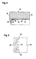
- the stiffener elements 46, 46' are connected to a metal plate 48 attached to the lower surface 16 of the floor panel 10.
- the stiffener element 46 is formed in one piece with the metal plate 48.
- a marginal region 50 of the metal plate 48 is folded so as to form the stiffener element 46.
- the edge 52 of the marginal region 50 is welded to the lower surface 54 of the metal plate 48 facing away from the floor panel 10.
- the stiffener element 46 can be arranged right at the edge of the floor panel 10 as shown In Fig.5 or 8 , or slightly in retreat as shown in Figs 6 and 7 .
- the stiffener element can be formed so as to have a generally triangular cross-section as shown in Figs 5, 6 or 8 , or a generally rectangular cross-section as shown in Fig.7 . It will be understood that many other configurations are possible.
- the lugs 36 are preferably also connected to the metal plate 48, either formed in one piece therewith or welded thereon. This will increase the strength of the assembly.
- the metal plate 48 can comprise one or more blocking tabs 56 for receiving the edge 52 of the stiffener element 46 in engagement between the blocking tabs 56 and the metal plate 48.
- Such blocking tabs 56 can be seen on Figs 8 and 9 .
- the blocking tabs 56 are formed in one piece with the metal plate 48.
- a floor panel for an elevated floor assembly commonly has a square shape. However it is not excluded to design the elevated floor assembly with floor panels having any other polygonal shape.
Landscapes
- Engineering & Computer Science (AREA)
- Architecture (AREA)
- General Engineering & Computer Science (AREA)
- Civil Engineering (AREA)
- Structural Engineering (AREA)
- Floor Finish (AREA)
- Bridges Or Land Bridges (AREA)
- Specific Sealing Or Ventilating Devices For Doors And Windows (AREA)
- Non-Portable Lighting Devices Or Systems Thereof (AREA)
- Body Structure For Vehicles (AREA)
Claims (9)
- Aufgeständerte Fußbodenanordnung umfassend.
Bodenplatten (10, 10', 10") mit einer oberen Oberfläche (14), einer gegenüberliegenden unteren Oberfläche (16) und Seitenflächen (18, 18'), wobei sich zwei benachbarte Seitenflächen (18, 18') in Eckabschnitten (20) der Bodenplatte treffen; und
Tragfüße (12) zum Tragen der Bodenplatten (10, 10', 10") über einem Grundboden, wobei die Tragfüße (12) einen Schaft (22) umfassen, der ein mit einer Grundplatte (28) verbundenes unteres Ende (26) zur Auflage auf dem Grundboden und ein mit einer Tragsäule (30) verbundenes oberes Ende (24) zum Tragen der Bodenplatten (10, 10', 10") aufweist, wobei die Tragsäule (30) ein Aufnahmeende (34) umfasst, wobei das Aufnahmeende (34) ein zylindrisches Hohlelement ist, welches verkürzt werden kann, um eine wesentliche Höhenreduzierung des Tragfußes (12) zu bewirken,
dadurch gekennzeichnet, dass
die Bodenplatten (10) Vorsprünge (36, 36', 36") auf der unteren Oberfläche (16) im Bereich der Eckabschnitte (20) umfassen, wobei sich die Vorsprünge (36, 36', 36") in einer im Wesentlichen senkrecht zur unteren Oberfläche (16) und fort von der Bodenplatte (10, 10', 10") verlaufenden Richtung erstrecken, und
das Aufnahmeende (34) zur Aufnahme der Vorsprünge (36, 36', 36") darin dient, und
die Bodenplatten (10, 10', 10") ferner eine Metallplatte (48) auf der unteren Oberfläche (16) umfassen, wobei jede Bodenplatte (10, 10', 10") Versteifungselemente (46, 46') umfasst, wobei die Versteifungselemente (46, 46') auf der unteren Oberfläche (16) der Bodenplatte (10, 10', 10") entlang der Seitenflächen (18, 18') angeordnet sind und sich in einer generell senkrechten Richtung von der Bodenplatte (10, 10', 10") fort erstrecken, wobei die Versteifungselemente (46, 46') durch Biegen von Randbereichen (50) der Metallplatte (48) einstückig mit der Metallplatte (48) ausgebildet sind, wobei die Kanten der Randbereiche (50) abgewandt von der Bodenplatte an die untere Oberfläche der Metallplatte (48) angeschweißt sind - Aufgeständerte Fußbodenanordnung nach Anspruch 1, wobei der Vorsprung (36, 36', 36") einen ersten Vorsprungabschnitt (38) und einen benachbarten zweiten Vorsprungabschnitt (38') umfasst, wobei sich der erste Vorsprungabschnitt (38) in einer im Wesentlichen parallel zu einer Ebene einer ersten Seitenfläche (18) der Bodenplatte (10, 10', 10") verlaufenden Ebene befindet, wobei sich der zweite Vorsprungabschnitt (38') in einer im Wesentlichen parallel zu einer Ebene einer zweiten Seitenfläche (18') der Bodenplatte (10, 10', 10") verlaufenden Ebene befindet, wobei die zweite Seitenfläche (18') der ersten Seitenfläche (18) benachbart ist
- Aufgeständerte Fußbodenanordnung nach Anspruch 2, wobei der erste und zweite Vorsprungabschnitt (38, 38') in derselben Ebene wie die erste und zweite Seitenfläche (18, 18') der Bodenplatte (10, 10', 10") angeordnet sind
- Aufgeständerte Fußbodenanordnung nach irgendeinem der vorangehenden Ansprüche, wobei der Vorsprung (36, 36', 36") eine Verjüngung in einer von der Bodenplatte (10, 10', 10") fort verlaufenden Richtung umfasst
- Aufgeständerte Fußbodenanordnung nach irgendeinem der vorangehenden Ansprüche, wobei das Aufnahmeende (34) derart bemessen ist, dass es die Vorsprünge (36, 36', 36") aller sich über einem Tragfuß (12) treffenden Eckabschnitte (20) aufnimmt.
- Aufgeständerte Fußbodenanordnung nach irgendeinem der vorangehenden Ansprüche, wobei der Schaft (22) ein Gewinde und eine Mutter (40) mit einem entsprechenden Innengewinde umfasst, wobei die Tragsäule (30) derart ausgelegt ist, dass sie den Schaft (22) in Eingriff nimmt und auf der Mutter (40) aufliegt
- Aufgeständerte Fußbodenanordnung nach Anspruch 1, wobei die Versteifungselemente (46, 46') einen generell rechteckigen oder dreieckigen Querschnitt aufweisen
- Aufgeständerte Fußbodenanordnung nach Anspruch 1 oder 7, wobei die Versteifungselemente (46, 46') auf der Kante der Bodenplatte (10, 10', 10") oder etwas zurückversetzt zur Kante der Bodenplatte (10, 10', 10") angeordnet sind
- Aufgeständerte Fußbodenanordnung nach irgendeinem der vorangehenden Ansprüche, wobei die Metallplatte (48) mindestens einen Sperrzapfen (56) zur Aufnahme einer Kante des Versteifungselements (46, 46') in Eingriff zwischen dem mindestens einen Sperrzapfen (56) und der Metallplatte (48) umfasst
Applications Claiming Priority (3)
| Application Number | Priority Date | Filing Date | Title |
|---|---|---|---|
| LU91018A LU91018B1 (en) | 2003-04-01 | 2003-04-01 | Elevated floor assembly. |
| LU91018 | 2003-04-01 | ||
| PCT/EP2004/050416 WO2004088063A1 (en) | 2003-04-01 | 2004-04-01 | Elevated floor assembly |
Publications (2)
| Publication Number | Publication Date |
|---|---|
| EP1608827A1 EP1608827A1 (de) | 2005-12-28 |
| EP1608827B1 true EP1608827B1 (de) | 2011-06-29 |
Family
ID=33129068
Family Applications (1)
| Application Number | Title | Priority Date | Filing Date |
|---|---|---|---|
| EP04725058A Expired - Lifetime EP1608827B1 (de) | 2003-04-01 | 2004-04-01 | Erhöhter fussboden |
Country Status (10)
| Country | Link |
|---|---|
| EP (1) | EP1608827B1 (de) |
| JP (1) | JP4659735B2 (de) |
| CN (1) | CN100417779C (de) |
| AT (1) | ATE514824T1 (de) |
| DK (1) | DK1608827T3 (de) |
| ES (1) | ES2372250T3 (de) |
| LU (1) | LU91018B1 (de) |
| RU (1) | RU2327018C2 (de) |
| WO (1) | WO2004088063A1 (de) |
| ZA (1) | ZA200507852B (de) |
Families Citing this family (1)
| Publication number | Priority date | Publication date | Assignee | Title |
|---|---|---|---|---|
| JP2012154172A (ja) * | 2012-05-21 | 2012-08-16 | Kumagai Gumi Co Ltd | 補強床パネル |
Citations (2)
| Publication number | Priority date | Publication date | Assignee | Title |
|---|---|---|---|---|
| GB2154261A (en) * | 1984-02-17 | 1985-09-04 | Krantz H Gmbh & Co | Floor shuttering |
| DE29520100U1 (de) * | 1995-12-19 | 1996-02-08 | Schmitt Karl Gmbh | Hohlraumboden |
Family Cites Families (9)
| Publication number | Priority date | Publication date | Assignee | Title |
|---|---|---|---|---|
| GB876117A (en) * | 1958-01-23 | 1961-08-30 | Walter Franklin Pawlowski | Elevated sectional flooring |
| US3295272A (en) * | 1963-08-07 | 1967-01-03 | Furukawa Casting Company Ltd | Raised floor construction |
| GB8417605D0 (en) * | 1984-07-10 | 1984-08-15 | Floorplan Electrica Ltd | Access floor structure |
| JPS6213650A (ja) * | 1985-07-10 | 1987-01-22 | 未来工業株式会社 | 床材 |
| IT1227965B (it) | 1988-11-02 | 1991-05-20 | Sisa S A | Piedino per pavimenti sopraelevati. |
| US5333423A (en) * | 1992-12-23 | 1994-08-02 | Propst Robert L | Floor system |
| US5499476A (en) * | 1993-08-31 | 1996-03-19 | Interface, Inc. | Low profile raised panel flooring with metal support structure |
| DE29707739U1 (de) * | 1997-04-29 | 1997-08-28 | Mächtle-Wöhler, Margot, 70825 Korntal-Münchingen | Hohlraumstütze |
| EP1143083A1 (de) * | 2000-03-31 | 2001-10-10 | Martin Lange | Formplattenverbund aus Formplatten und Auflagemodulen und Arbeitsverfahren zur Herstellung eines solchen |
-
2003
- 2003-04-01 LU LU91018A patent/LU91018B1/en active
-
2004
- 2004-04-01 RU RU2005133477/03A patent/RU2327018C2/ru not_active IP Right Cessation
- 2004-04-01 ES ES04725058T patent/ES2372250T3/es not_active Expired - Lifetime
- 2004-04-01 AT AT04725058T patent/ATE514824T1/de not_active IP Right Cessation
- 2004-04-01 WO PCT/EP2004/050416 patent/WO2004088063A1/en not_active Ceased
- 2004-04-01 EP EP04725058A patent/EP1608827B1/de not_active Expired - Lifetime
- 2004-04-01 CN CNB2004800087758A patent/CN100417779C/zh not_active Expired - Fee Related
- 2004-04-01 JP JP2006505510A patent/JP4659735B2/ja not_active Expired - Fee Related
- 2004-04-01 DK DK04725058.4T patent/DK1608827T3/da active
-
2005
- 2005-09-28 ZA ZA200507852A patent/ZA200507852B/xx unknown
Patent Citations (2)
| Publication number | Priority date | Publication date | Assignee | Title |
|---|---|---|---|---|
| GB2154261A (en) * | 1984-02-17 | 1985-09-04 | Krantz H Gmbh & Co | Floor shuttering |
| DE29520100U1 (de) * | 1995-12-19 | 1996-02-08 | Schmitt Karl Gmbh | Hohlraumboden |
Also Published As
| Publication number | Publication date |
|---|---|
| JP2006522243A (ja) | 2006-09-28 |
| JP4659735B2 (ja) | 2011-03-30 |
| CN100417779C (zh) | 2008-09-10 |
| RU2005133477A (ru) | 2006-05-27 |
| RU2327018C2 (ru) | 2008-06-20 |
| WO2004088063A1 (en) | 2004-10-14 |
| ATE514824T1 (de) | 2011-07-15 |
| ZA200507852B (en) | 2007-03-28 |
| DK1608827T3 (da) | 2011-09-26 |
| LU91018B1 (en) | 2004-10-04 |
| EP1608827A1 (de) | 2005-12-28 |
| CN1777728A (zh) | 2006-05-24 |
| ES2372250T3 (es) | 2012-01-17 |
Similar Documents
| Publication | Publication Date | Title |
|---|---|---|
| KR101572499B1 (ko) | 프리 액세스플로어 구조체의 시공방법 | |
| US8074955B2 (en) | Method and apparatus for improving the strength of a utility pole | |
| US20050204621A1 (en) | Panelized planter box system and method of forming same | |
| JP2014152545A (ja) | ソーラーパネル取付架台 | |
| EP1608827B1 (de) | Erhöhter fussboden | |
| KR102382182B1 (ko) | 이중 마루용 레벨링 포스트 및 이를 포함하는 이중 마루 설치 구조 | |
| US4981005A (en) | Tapered pole and method of making | |
| KR101326665B1 (ko) | 클린룸의 플로어시스템 | |
| JP5042811B2 (ja) | フリーアクセスフロア用架台 | |
| JP6214312B2 (ja) | パイプサポート用大引き材受金物 | |
| JP5042812B2 (ja) | フリーアクセスフロア用架台 | |
| JP4341902B2 (ja) | 圧縮機支持構造 | |
| JP5133184B2 (ja) | フリーアクセスフロア用架台 | |
| IE930490A1 (en) | Roof structures | |
| KR102316057B1 (ko) | 코일 적재용 지지 장치 | |
| JP5133181B2 (ja) | フリーアクセスフロア用架台 | |
| JP7297621B2 (ja) | デッキ構造およびデッキの施工方法 | |
| EP4239143B1 (de) | Kopf mit umkehrbarem adapter zur stütze von doppelböden | |
| JP5187801B2 (ja) | パネル支持構造 | |
| US20260096647A1 (en) | Hot rolled storage rack systems and methods | |
| JPH0137491Y2 (de) | ||
| JP5133183B2 (ja) | フリーアクセスフロア用架台 | |
| JP2984533B2 (ja) | 土砂用ホッパ及び土砂用ホッパの設置方法 | |
| CN1045649C (zh) | 建筑模板 | |
| KR100371219B1 (ko) | 클린룸용 바닥패널의 보강 지지구조 |
Legal Events
| Date | Code | Title | Description |
|---|---|---|---|
| PUAI | Public reference made under article 153(3) epc to a published international application that has entered the european phase |
Free format text: ORIGINAL CODE: 0009012 |
|
| 17P | Request for examination filed |
Effective date: 20050921 |
|
| AK | Designated contracting states |
Kind code of ref document: A1 Designated state(s): AT BE BG CH CY CZ DE DK EE ES FI FR GB GR HU IE IT LI LU MC NL PL PT RO SE SI SK TR |
|
| AX | Request for extension of the european patent |
Extension state: AL HR LT LV MK |
|
| RAP1 | Party data changed (applicant data changed or rights of an application transferred) |
Owner name: UNIFLAIR S.P.A. |
|
| DAX | Request for extension of the european patent (deleted) | ||
| 17Q | First examination report despatched |
Effective date: 20080416 |
|
| GRAP | Despatch of communication of intention to grant a patent |
Free format text: ORIGINAL CODE: EPIDOSNIGR1 |
|
| GRAS | Grant fee paid |
Free format text: ORIGINAL CODE: EPIDOSNIGR3 |
|
| GRAA | (expected) grant |
Free format text: ORIGINAL CODE: 0009210 |
|
| AK | Designated contracting states |
Kind code of ref document: B1 Designated state(s): AT BE BG CH CY CZ DE DK EE ES FI FR GB GR HU IE IT LI LU MC NL PL PT RO SE SI SK TR |
|
| REG | Reference to a national code |
Ref country code: GB Ref legal event code: FG4D |
|
| REG | Reference to a national code |
Ref country code: CH Ref legal event code: EP |
|
| REG | Reference to a national code |
Ref country code: IE Ref legal event code: FG4D |
|
| REG | Reference to a national code |
Ref country code: DE Ref legal event code: R096 Ref document number: 602004033277 Country of ref document: DE Effective date: 20110818 |
|
| REG | Reference to a national code |
Ref country code: DK Ref legal event code: T3 |
|
| REG | Reference to a national code |
Ref country code: NL Ref legal event code: VDEP Effective date: 20110629 |
|
| PG25 | Lapsed in a contracting state [announced via postgrant information from national office to epo] |
Ref country code: SE Free format text: LAPSE BECAUSE OF FAILURE TO SUBMIT A TRANSLATION OF THE DESCRIPTION OR TO PAY THE FEE WITHIN THE PRESCRIBED TIME-LIMIT Effective date: 20110629 |
|
| PG25 | Lapsed in a contracting state [announced via postgrant information from national office to epo] |
Ref country code: AT Free format text: LAPSE BECAUSE OF FAILURE TO SUBMIT A TRANSLATION OF THE DESCRIPTION OR TO PAY THE FEE WITHIN THE PRESCRIBED TIME-LIMIT Effective date: 20110629 Ref country code: GR Free format text: LAPSE BECAUSE OF FAILURE TO SUBMIT A TRANSLATION OF THE DESCRIPTION OR TO PAY THE FEE WITHIN THE PRESCRIBED TIME-LIMIT Effective date: 20110930 Ref country code: FI Free format text: LAPSE BECAUSE OF FAILURE TO SUBMIT A TRANSLATION OF THE DESCRIPTION OR TO PAY THE FEE WITHIN THE PRESCRIBED TIME-LIMIT Effective date: 20110629 Ref country code: SI Free format text: LAPSE BECAUSE OF FAILURE TO SUBMIT A TRANSLATION OF THE DESCRIPTION OR TO PAY THE FEE WITHIN THE PRESCRIBED TIME-LIMIT Effective date: 20110629 |
|
| PG25 | Lapsed in a contracting state [announced via postgrant information from national office to epo] |
Ref country code: BE Free format text: LAPSE BECAUSE OF FAILURE TO SUBMIT A TRANSLATION OF THE DESCRIPTION OR TO PAY THE FEE WITHIN THE PRESCRIBED TIME-LIMIT Effective date: 20110629 |
|
| REG | Reference to a national code |
Ref country code: ES Ref legal event code: FG2A Ref document number: 2372250 Country of ref document: ES Kind code of ref document: T3 Effective date: 20120117 |
|
| PG25 | Lapsed in a contracting state [announced via postgrant information from national office to epo] |
Ref country code: NL Free format text: LAPSE BECAUSE OF FAILURE TO SUBMIT A TRANSLATION OF THE DESCRIPTION OR TO PAY THE FEE WITHIN THE PRESCRIBED TIME-LIMIT Effective date: 20110629 Ref country code: EE Free format text: LAPSE BECAUSE OF FAILURE TO SUBMIT A TRANSLATION OF THE DESCRIPTION OR TO PAY THE FEE WITHIN THE PRESCRIBED TIME-LIMIT Effective date: 20110629 Ref country code: PT Free format text: LAPSE BECAUSE OF FAILURE TO SUBMIT A TRANSLATION OF THE DESCRIPTION OR TO PAY THE FEE WITHIN THE PRESCRIBED TIME-LIMIT Effective date: 20111031 Ref country code: CZ Free format text: LAPSE BECAUSE OF FAILURE TO SUBMIT A TRANSLATION OF THE DESCRIPTION OR TO PAY THE FEE WITHIN THE PRESCRIBED TIME-LIMIT Effective date: 20110629 |
|
| PG25 | Lapsed in a contracting state [announced via postgrant information from national office to epo] |
Ref country code: CY Free format text: LAPSE BECAUSE OF FAILURE TO SUBMIT A TRANSLATION OF THE DESCRIPTION OR TO PAY THE FEE WITHIN THE PRESCRIBED TIME-LIMIT Effective date: 20110629 Ref country code: RO Free format text: LAPSE BECAUSE OF FAILURE TO SUBMIT A TRANSLATION OF THE DESCRIPTION OR TO PAY THE FEE WITHIN THE PRESCRIBED TIME-LIMIT Effective date: 20110629 Ref country code: SK Free format text: LAPSE BECAUSE OF FAILURE TO SUBMIT A TRANSLATION OF THE DESCRIPTION OR TO PAY THE FEE WITHIN THE PRESCRIBED TIME-LIMIT Effective date: 20110629 Ref country code: PL Free format text: LAPSE BECAUSE OF FAILURE TO SUBMIT A TRANSLATION OF THE DESCRIPTION OR TO PAY THE FEE WITHIN THE PRESCRIBED TIME-LIMIT Effective date: 20110629 |
|
| PLBE | No opposition filed within time limit |
Free format text: ORIGINAL CODE: 0009261 |
|
| STAA | Information on the status of an ep patent application or granted ep patent |
Free format text: STATUS: NO OPPOSITION FILED WITHIN TIME LIMIT |
|
| 26N | No opposition filed |
Effective date: 20120330 |
|
| REG | Reference to a national code |
Ref country code: DE Ref legal event code: R097 Ref document number: 602004033277 Country of ref document: DE Effective date: 20120330 |
|
| PG25 | Lapsed in a contracting state [announced via postgrant information from national office to epo] |
Ref country code: MC Free format text: LAPSE BECAUSE OF NON-PAYMENT OF DUE FEES Effective date: 20120430 |
|
| REG | Reference to a national code |
Ref country code: CH Ref legal event code: PL |
|
| REG | Reference to a national code |
Ref country code: IE Ref legal event code: MM4A |
|
| PG25 | Lapsed in a contracting state [announced via postgrant information from national office to epo] |
Ref country code: IE Free format text: LAPSE BECAUSE OF NON-PAYMENT OF DUE FEES Effective date: 20120401 Ref country code: CH Free format text: LAPSE BECAUSE OF NON-PAYMENT OF DUE FEES Effective date: 20120430 Ref country code: LI Free format text: LAPSE BECAUSE OF NON-PAYMENT OF DUE FEES Effective date: 20120430 |
|
| PG25 | Lapsed in a contracting state [announced via postgrant information from national office to epo] |
Ref country code: BG Free format text: LAPSE BECAUSE OF FAILURE TO SUBMIT A TRANSLATION OF THE DESCRIPTION OR TO PAY THE FEE WITHIN THE PRESCRIBED TIME-LIMIT Effective date: 20110929 |
|
| PG25 | Lapsed in a contracting state [announced via postgrant information from national office to epo] |
Ref country code: TR Free format text: LAPSE BECAUSE OF FAILURE TO SUBMIT A TRANSLATION OF THE DESCRIPTION OR TO PAY THE FEE WITHIN THE PRESCRIBED TIME-LIMIT Effective date: 20110629 |
|
| PG25 | Lapsed in a contracting state [announced via postgrant information from national office to epo] |
Ref country code: LU Free format text: LAPSE BECAUSE OF NON-PAYMENT OF DUE FEES Effective date: 20120401 |
|
| PG25 | Lapsed in a contracting state [announced via postgrant information from national office to epo] |
Ref country code: HU Free format text: LAPSE BECAUSE OF FAILURE TO SUBMIT A TRANSLATION OF THE DESCRIPTION OR TO PAY THE FEE WITHIN THE PRESCRIBED TIME-LIMIT Effective date: 20040401 |
|
| REG | Reference to a national code |
Ref country code: FR Ref legal event code: PLFP Year of fee payment: 13 |
|
| REG | Reference to a national code |
Ref country code: FR Ref legal event code: PLFP Year of fee payment: 14 |
|
| REG | Reference to a national code |
Ref country code: FR Ref legal event code: PLFP Year of fee payment: 15 |
|
| PGFP | Annual fee paid to national office [announced via postgrant information from national office to epo] |
Ref country code: DE Payment date: 20180427 Year of fee payment: 15 Ref country code: DK Payment date: 20180426 Year of fee payment: 15 Ref country code: ES Payment date: 20180503 Year of fee payment: 15 |
|
| PGFP | Annual fee paid to national office [announced via postgrant information from national office to epo] |
Ref country code: IT Payment date: 20180423 Year of fee payment: 15 Ref country code: FR Payment date: 20180425 Year of fee payment: 15 |
|
| PGFP | Annual fee paid to national office [announced via postgrant information from national office to epo] |
Ref country code: GB Payment date: 20180427 Year of fee payment: 15 |
|
| REG | Reference to a national code |
Ref country code: DE Ref legal event code: R119 Ref document number: 602004033277 Country of ref document: DE |
|
| REG | Reference to a national code |
Ref country code: DK Ref legal event code: EBP Effective date: 20190430 |
|
| GBPC | Gb: european patent ceased through non-payment of renewal fee |
Effective date: 20190401 |
|
| PG25 | Lapsed in a contracting state [announced via postgrant information from national office to epo] |
Ref country code: DE Free format text: LAPSE BECAUSE OF NON-PAYMENT OF DUE FEES Effective date: 20191101 Ref country code: GB Free format text: LAPSE BECAUSE OF NON-PAYMENT OF DUE FEES Effective date: 20190401 |
|
| PG25 | Lapsed in a contracting state [announced via postgrant information from national office to epo] |
Ref country code: IT Free format text: LAPSE BECAUSE OF NON-PAYMENT OF DUE FEES Effective date: 20190401 Ref country code: DK Free format text: LAPSE BECAUSE OF NON-PAYMENT OF DUE FEES Effective date: 20190430 |
|
| PG25 | Lapsed in a contracting state [announced via postgrant information from national office to epo] |
Ref country code: FR Free format text: LAPSE BECAUSE OF NON-PAYMENT OF DUE FEES Effective date: 20190430 |
|
| REG | Reference to a national code |
Ref country code: ES Ref legal event code: FD2A Effective date: 20200828 |
|
| PG25 | Lapsed in a contracting state [announced via postgrant information from national office to epo] |
Ref country code: ES Free format text: LAPSE BECAUSE OF NON-PAYMENT OF DUE FEES Effective date: 20190402 |