EP1609032B1 - Soupape d'injection de carburant et systeme a combustion interne - Google Patents
Soupape d'injection de carburant et systeme a combustion interne Download PDFInfo
- Publication number
- EP1609032B1 EP1609032B1 EP03747820A EP03747820A EP1609032B1 EP 1609032 B1 EP1609032 B1 EP 1609032B1 EP 03747820 A EP03747820 A EP 03747820A EP 03747820 A EP03747820 A EP 03747820A EP 1609032 B1 EP1609032 B1 EP 1609032B1
- Authority
- EP
- European Patent Office
- Prior art keywords
- internal combustion
- combustion engine
- transponder
- fuel injection
- data
- Prior art date
- Legal status (The legal status is an assumption and is not a legal conclusion. Google has not performed a legal analysis and makes no representation as to the accuracy of the status listed.)
- Expired - Lifetime
Links
Images
Classifications
-
- F—MECHANICAL ENGINEERING; LIGHTING; HEATING; WEAPONS; BLASTING
- F02—COMBUSTION ENGINES; HOT-GAS OR COMBUSTION-PRODUCT ENGINE PLANTS
- F02D—CONTROLLING COMBUSTION ENGINES
- F02D41/00—Electrical control of supply of combustible mixture or its constituents
- F02D41/24—Electrical control of supply of combustible mixture or its constituents characterised by the use of digital means
-
- F—MECHANICAL ENGINEERING; LIGHTING; HEATING; WEAPONS; BLASTING
- F02—COMBUSTION ENGINES; HOT-GAS OR COMBUSTION-PRODUCT ENGINE PLANTS
- F02M—SUPPLYING COMBUSTION ENGINES IN GENERAL WITH COMBUSTIBLE MIXTURES OR CONSTITUENTS THEREOF
- F02M61/00—Fuel-injectors not provided for in groups F02M39/00 - F02M57/00 or F02M67/00
- F02M61/16—Details not provided for in, or of interest apart from, the apparatus of groups F02M61/02 - F02M61/14
- F02M61/168—Assembling; Disassembling; Manufacturing; Adjusting
-
- F—MECHANICAL ENGINEERING; LIGHTING; HEATING; WEAPONS; BLASTING
- F02—COMBUSTION ENGINES; HOT-GAS OR COMBUSTION-PRODUCT ENGINE PLANTS
- F02D—CONTROLLING COMBUSTION ENGINES
- F02D41/00—Electrical control of supply of combustible mixture or its constituents
- F02D41/24—Electrical control of supply of combustible mixture or its constituents characterised by the use of digital means
- F02D41/2406—Electrical control of supply of combustible mixture or its constituents characterised by the use of digital means using essentially read only memories
- F02D41/2425—Particular ways of programming the data
- F02D41/2429—Methods of calibrating or learning
- F02D41/2432—Methods of calibration
- F02D41/2435—Methods of calibration characterised by the writing medium, e.g. bar code
-
- F—MECHANICAL ENGINEERING; LIGHTING; HEATING; WEAPONS; BLASTING
- F02—COMBUSTION ENGINES; HOT-GAS OR COMBUSTION-PRODUCT ENGINE PLANTS
- F02D—CONTROLLING COMBUSTION ENGINES
- F02D41/00—Electrical control of supply of combustible mixture or its constituents
- F02D41/24—Electrical control of supply of combustible mixture or its constituents characterised by the use of digital means
- F02D41/2406—Electrical control of supply of combustible mixture or its constituents characterised by the use of digital means using essentially read only memories
- F02D41/2425—Particular ways of programming the data
- F02D41/2429—Methods of calibrating or learning
- F02D41/2451—Methods of calibrating or learning characterised by what is learned or calibrated
- F02D41/2464—Characteristics of actuators
- F02D41/2467—Characteristics of actuators for injectors
-
- F—MECHANICAL ENGINEERING; LIGHTING; HEATING; WEAPONS; BLASTING
- F02—COMBUSTION ENGINES; HOT-GAS OR COMBUSTION-PRODUCT ENGINE PLANTS
- F02M—SUPPLYING COMBUSTION ENGINES IN GENERAL WITH COMBUSTIBLE MIXTURES OR CONSTITUENTS THEREOF
- F02M61/00—Fuel-injectors not provided for in groups F02M39/00 - F02M57/00 or F02M67/00
- F02M61/16—Details not provided for in, or of interest apart from, the apparatus of groups F02M61/02 - F02M61/14
-
- G—PHYSICS
- G05—CONTROLLING; REGULATING
- G05B—CONTROL OR REGULATING SYSTEMS IN GENERAL; FUNCTIONAL ELEMENTS OF SUCH SYSTEMS; MONITORING OR TESTING ARRANGEMENTS FOR SUCH SYSTEMS OR ELEMENTS
- G05B19/00—Program-control systems
- G05B19/02—Program-control systems electric
- G05B19/04—Program control other than numerical control, i.e. in sequence controllers or logic controllers
- G05B19/12—Program control other than numerical control, i.e. in sequence controllers or logic controllers using record carriers
-
- F—MECHANICAL ENGINEERING; LIGHTING; HEATING; WEAPONS; BLASTING
- F02—COMBUSTION ENGINES; HOT-GAS OR COMBUSTION-PRODUCT ENGINE PLANTS
- F02M—SUPPLYING COMBUSTION ENGINES IN GENERAL WITH COMBUSTIBLE MIXTURES OR CONSTITUENTS THEREOF
- F02M2200/00—Details of fuel-injection apparatus, not otherwise provided for
- F02M2200/80—Fuel injection apparatus manufacture, repair or assembly
- F02M2200/8007—Storing data on fuel injection apparatus, e.g. by printing, by using bar codes or EPROMs
Definitions
- the invention relates to a fuel injection valve according to the preamble of claim 1.
- a fuel injection valve may in particular be an injector fueled by a pressure accumulator is supplied under high pressure (eg 1600 bar), wherein the injector for injecting into the combustion chamber of an internal combustion engine releases or blocks injection nozzles of the fuel injection valve.
- the fuel injection valve may, for. B. also be a so-called pump-nozzle unit, the fuel is supplied under a pressure insufficient for injection pressure, and the pump-nozzle unit generates the high pressure required for injection and performs the injection process.
- Known such fuel injection valves wear on labeling fields a variety of information in plain text, so readable to the human eye. The information may include type designation, usage information, manufacturing time.
- Fuel injection valves according to the preamble of claim 1 are known from the publications WO 03 / 081353A (Vero preteings date 02.10.2003) and DE 101 17 8091.
- the advantage of the fuel injection valve according to the invention according to claim 1 is that because the transponder can be equipped with an electronic memory of very large capacity, many data can be electronically stored. It is therefore no longer necessary for the above-mentioned known matrix memory, so that its place for labels for Available. It can therefore also reading errors when reading the digital matrix memory by means of camera, for example, as a result of a tilt of the camera does not occur.
- the stored data can contain all the properties and technical parameters of the injector. These include, in particular, measured values measured for this particular fuel injection valve during manufacture or after a repair. In the latter case, data in the transponder, which are no longer needed, can be deleted by a writing device for the transponder and overwritten with current values.
- the data stored in the factory may also be of interest in the manufacture of the individual parts of the injector (for simplicity, the fuel injector will often be referred to as an injector, although, as noted above, other types of injectors fall within the invention)
- Data e.g. As mechanical dimensions, number of processing station, date of manufacture or batch number are stored in the transponder. This can make it easier to find the causes of errors. Since the transponder does not change the shape of the injector head and is housed inside the injector head, any change in workpiece carriers that hold the injector or injector head in different stations of the assembly line is not required. The parts of the labels in plain text that should be visible from afar can be better positioned. Dirt is of no importance for reading and storing the data of the transponder.
- this is fed in embodiments of the invention by a battery;
- this preferably has an induction coil which captures by reading or writing by means of a reading or writing device (or a reading or writing device) of this radio waves emitted or a low-frequency electromagnetic field and from this electrical energy for operating the transponder and the transmitter - and receiving device wins.
- To send the data read in the transponder can also serve the said coil.
- the invention also relates to an internal combustion engine system according to the preamble of claim 2.
- the invention according to the characterizing part of claim 2 has has the advantage that the control unit can evaluate data stored in the injector (in its transponder) for the controller. This makes it possible, for example, an automatic fine adjustment of the controller to values of the injector, although they are within a permissible range of fluctuation, but should still be considered an individual for optimum control of the engine.
- the transponder memory For maintenance purposes in the workshop, it may be sufficient to read the contents of the transponder memory with a reading device, possibly also a reading and writing device that is to be operated manually, or to describe the transponder with further values.
- a reading device possibly also a reading and writing device that is to be operated manually, or to describe the transponder with further values.
- the advantage of the embodiment according to claim 3 is that said device is fixed in place and therefore can be constantly available, even while driving or more generally the operation of the engine.
- Both the mentioned hand-operated reader and the fixed reading device can be designed so that they allow all injectors of the internal combustion engine system to be read out almost simultaneously or in response to a command triggered by the user or by the control device.
- the z. B. are used for the following purposes: evidence of required maintenance at the next inspection of the vehicle; Evidence of driving conditions that may have contributed to failure of the injector.
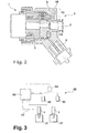
- an injector 1 for injecting fuel delivered at high pressure (about 1600 bar) into a combustion chamber of a diesel engine has an injector head 2, at the left side of which in FIG. 2 further parts of the injector 1 connect, in particular one formed from metal housing with slidably disposed therein valve piston, and an armature of a solenoid valve which cooperates with a arranged in the injector 2 magnetic coil 3.
- the devices not shown are conventional designs and devices of injectors.
- the injector head has an encapsulation 5 made of plastic for external protection, which also serves to fasten some parts.
- a connection 7 for a leakage line and electrical connections 8 for supplying the magnetic coil 3 are provided. The fuel is supplied to the injector at a location not shown.
- a transponder 15 is contained in the plastic extrusion 12 and hermetically sealed against external influences. It is located in an area below the labeling field 10.
- the transponder 15 has a semiconductor chip, which forms a data memory 16 and also contains electronics 17 for transmitting and receiving signals, as well as a wire coil (not shown in FIG 2-turn example) for transmitting and receiving, which is connected to the electronics 17 and serves to power the transponder and to receive and transmit electromagnetic signals.
- the signals are those in the radio wave range.
- the transponder is for transmitting and receiving low frequency signals, e.g. B. at about 10 kHz, formed, and in this case is a data transmission and operating power transmission by transformer coupling.
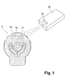
- a reading and writing device 20 (FIG. 1) contains transmitting devices and receiving devices as well as an antenna essentially formed by a coil for transmitting and receiving signals to and from the transponder 15.
- the device 20 has a visual display 22 and in its interior a data memory and an interface that allows the coupling of the device 20 to a computer of a repair operation.
- data of interest is directly visible on the display 22, in addition they can be transferred from the device in which they are stored to a computer. Any error causes or other comments determined by the workshop can be entered by the computer into the reading and writing device and then stored by the computer in the transponder 15.
- the transponder 15 contains data of the production and measured values which were determined by the manufacturer during tests of the injector 1 and were preferably entered into the transponder by transmitters coupled with production systems or measuring systems.
- FIG. 3 shows a simplified schematic representation of an internal combustion engine system 30.
- the engine itself shows only two cylinders or combustion chambers 31 which are each supplied with fuel by an injector 1 during operation.
- a control unit 40 supplies electrical injection signals to the injectors 1 via control lines 41.
- Each of the injectors 1 is equipped with a transponder 15 shown in FIGS. 1 and 2.
- each of the injectors 1 is assigned a separate reading and writing device 50, which is installed fixedly in the internal combustion engine system. The arrangement is such that each of these devices 50 can exchange data only with its associated transponder.
- the range of the devices 50 and their mounting location is suitably chosen for this Embodiments of the invention, the unique assignment takes place in other ways, preferably by different codes and / or frequencies.
- Each of the devices 50 is connected to the controller 40.
- a single reader and writer 60 is provided, which is shown in dashed lines.
- the devices 50 are not present in this other embodiment.
- the device 60 is connected to the controller 40.
- the device 60 is arranged and configured such that it can exchange data with its associated plurality of transponders. For this, it may be necessary to make the range of the wireless data connections greater than with the devices 50.
- the controller 40 uses the data read by the devices 50 and the device 60 from the transponders to control the operation of the motor. In case of special incidents or even during normal operation, when a program stored in the control unit 40 or in the transponder prescribes this, data is stored in the transponders by the control unit 40.
Landscapes
- Engineering & Computer Science (AREA)
- Chemical & Material Sciences (AREA)
- Combustion & Propulsion (AREA)
- Mechanical Engineering (AREA)
- General Engineering & Computer Science (AREA)
- Manufacturing & Machinery (AREA)
- Physics & Mathematics (AREA)
- General Physics & Mathematics (AREA)
- Automation & Control Theory (AREA)
- Fuel-Injection Apparatus (AREA)
- Combined Controls Of Internal Combustion Engines (AREA)
Abstract
Claims (6)
- Injecteur de carburant (1) pour un moteur à combustion interne, comprenant une tête de soupape (2) pourvue d'au moins un champ d'inscription (10) pour des inscriptions en clair et un dispositif de stockage de données lisible par un dispositif de lecture,
caractérisé en ce qu'
un dispositif de stockage de données sous forme de transpondeur (15), pouvant être appelé par une liaison sans fil par des signaux électromagnétiques non optiques, est disposé à l'intérieur d'un moulage en matière plastique (5) de la tête de soupape (2), le transpondeur (15) présentant une mémoire (16) lisible et inscriptible de manière électronique. - Système de moteur à combustion interne (30), présentant au moins un injecteur de carburant (1) selon la revendication 1, comprenant un appareil de commande (40) pour commander au moins l'un des paramètres suivants : régime, arrivée de carburant, instant d'injection,
caractérisé en ce qu'
on prévoit un dispositif de lecture (50 ; 60) couplé à l'appareil de commande (40) pour lire les données stockées dans le transpondeur, et l'appareil de commande (40) est configuré pour exploiter les données lues pour la commande du système de moteur à combustion interne. - Système de moteur à combustion interne selon la revendication 2,
caractérisé en ce que
le dispositif de lecture est fixé dans le système de moteur à combustion interne. - Système de moteur à combustion interne selon la revendication 3,
caractérisé en ce qu'
un dispositif de lecture est associé à chaque injecteur de carburant. - Système de moteur à combustion interne selon la revendication 3,
caractérisé en ce qu'
un unique dispositif de lecture associé à plusieurs injecteurs de carburant, est configuré pour lire des données provenant de tous les transpondeurs. - Système de moteur à combustion interne selon l'une des revendications 2 à 5,
caractérisé en ce que
le dispositif de lecture est en outre configuré pour inscrire des données dans le transpondeur, et l'appareil de commande est configuré pour enregistrer des données dans au moins un transpondeur, lors de l'apparition d'un critère provenant du groupe suivant : atteinte d'un instant prédéterminé, écoulement d'une période de temps prédéterminée, atteinte d'un nombre prédéterminé d'heures de service, atteinte d'un nombre prédéterminé de kilomètres parcourus, apparition d'écarts entre les caractéristiques de fonctionnement du système de moteur à combustion interne et des valeurs de consigne.
Applications Claiming Priority (3)
| Application Number | Priority Date | Filing Date | Title |
|---|---|---|---|
| DE10312914 | 2003-03-22 | ||
| DE10312914A DE10312914A1 (de) | 2003-03-22 | 2003-03-22 | Kraftstoffeinspritzventil und Brennkraftmaschinenanlage |
| PCT/DE2003/002827 WO2004086158A1 (fr) | 2003-03-22 | 2003-08-25 | Soupape d'injection de carburant et systeme a combustion interne |
Publications (2)
| Publication Number | Publication Date |
|---|---|
| EP1609032A1 EP1609032A1 (fr) | 2005-12-28 |
| EP1609032B1 true EP1609032B1 (fr) | 2006-08-16 |
Family
ID=32946080
Family Applications (1)
| Application Number | Title | Priority Date | Filing Date |
|---|---|---|---|
| EP03747820A Expired - Lifetime EP1609032B1 (fr) | 2003-03-22 | 2003-08-25 | Soupape d'injection de carburant et systeme a combustion interne |
Country Status (6)
| Country | Link |
|---|---|
| EP (1) | EP1609032B1 (fr) |
| JP (1) | JP2006514211A (fr) |
| KR (1) | KR100995737B1 (fr) |
| CN (1) | CN100440087C (fr) |
| DE (2) | DE10312914A1 (fr) |
| WO (1) | WO2004086158A1 (fr) |
Families Citing this family (13)
| Publication number | Priority date | Publication date | Assignee | Title |
|---|---|---|---|---|
| DE102005001425A1 (de) * | 2005-01-12 | 2006-07-20 | Robert Bosch Gmbh | Vorrichtung zur Steuerung einer Brennkraftmaschine |
| JP2006220098A (ja) * | 2005-02-14 | 2006-08-24 | Hitachi Ltd | センサ若しくは電磁気的作動要素及び燃料噴射弁及びその制御方法又は駆動方法 |
| EP1719897A1 (fr) * | 2005-05-02 | 2006-11-08 | Siemens Aktiengesellschaft | Injecteur de carburant |
| DE102005050567A1 (de) * | 2005-10-21 | 2007-04-26 | Robert Bosch Gmbh | Brennstoffeinspritzventil und Verfahren zur Identifikation von Brennstoffeinspritzventilen |
| DE102006008759B4 (de) * | 2006-02-24 | 2021-09-30 | Borgwarner Ludwigsburg Gmbh | Dieselmotor für Fahrzeuge |
| DE102006029082B4 (de) * | 2006-06-24 | 2015-10-08 | Mtu Friedrichshafen Gmbh | Verfahren und Einrichtung zur Steuerung einer Brennkraftmaschine |
| DE102009029159A1 (de) * | 2009-09-03 | 2011-03-17 | Robert Bosch Gmbh | Fluideinspritzsystem |
| JP2016008516A (ja) * | 2014-06-23 | 2016-01-18 | 日野自動車株式会社 | コモンレール式燃料噴射システム |
| WO2016075087A1 (fr) * | 2014-11-11 | 2016-05-19 | Robert Bosch Gmbh | Injecteur de carburant comprenant une pièce modulaire |
| TR201513608A2 (tr) * | 2015-11-02 | 2017-02-21 | Bosch Sanayi Ve Tic A S | Yakin alan i̇leti̇m yoluyla tanimlama si̇stemi̇ne sahi̇p bi̇r yakitenjektörü ve bunun veri̇ i̇leti̇m metodu |
| JP6622641B2 (ja) * | 2016-04-04 | 2019-12-18 | ボッシュ株式会社 | 燃料噴射弁 |
| JP6841142B2 (ja) | 2017-04-13 | 2021-03-10 | 株式会社デンソー | インジェクタ取付装置、および、燃料噴射装置 |
| DE102021205992A1 (de) | 2021-06-14 | 2022-12-15 | Robert Bosch Gesellschaft mit beschränkter Haftung | Kraftstoffeinspritzsystem |
Family Cites Families (9)
| Publication number | Priority date | Publication date | Assignee | Title |
|---|---|---|---|---|
| US4742470A (en) * | 1985-12-30 | 1988-05-03 | Gte Valeron Corporation | Tool identification system |
| JPH01150879A (ja) * | 1987-12-08 | 1989-06-13 | Nissan Motor Co Ltd | 無線式生産管理情報媒体 |
| JP3511642B2 (ja) * | 1993-08-04 | 2004-03-29 | 株式会社デンソー | 内燃機関用制御装置 |
| CN1076291C (zh) * | 1994-04-14 | 2001-12-19 | 富士通坦株式会社 | 车辆防盗装置 |
| JPH08319865A (ja) * | 1995-05-26 | 1996-12-03 | Mitsubishi Motors Corp | 筒内噴射式内燃機関における燃料噴射制御装置 |
| US6516658B1 (en) * | 1999-04-16 | 2003-02-11 | Siemens Vdo Automotive Corporation | Identification of diesel engine injector characteristics |
| US6536268B1 (en) * | 1999-11-01 | 2003-03-25 | Siemens Vdo Automotive Corporation | Utilizing increasing width for identification voltages |
| DE10117809A1 (de) * | 2001-04-10 | 2002-10-17 | Bosch Gmbh Robert | System und Verfahren zum Erfassen von Informationen |
| DE10213349A1 (de) * | 2002-03-26 | 2003-10-09 | Bosch Gmbh Robert | System zum Erfassen von Informationen |
-
2003
- 2003-03-22 DE DE10312914A patent/DE10312914A1/de not_active Ceased
- 2003-08-25 KR KR1020057017655A patent/KR100995737B1/ko not_active Expired - Fee Related
- 2003-08-25 EP EP03747820A patent/EP1609032B1/fr not_active Expired - Lifetime
- 2003-08-25 DE DE50304695T patent/DE50304695D1/de not_active Expired - Lifetime
- 2003-08-25 WO PCT/DE2003/002827 patent/WO2004086158A1/fr not_active Ceased
- 2003-08-25 CN CNB038262045A patent/CN100440087C/zh not_active Expired - Fee Related
- 2003-08-25 JP JP2004569831A patent/JP2006514211A/ja active Pending
Also Published As
| Publication number | Publication date |
|---|---|
| KR100995737B1 (ko) | 2010-11-22 |
| JP2006514211A (ja) | 2006-04-27 |
| DE10312914A1 (de) | 2004-10-07 |
| CN1759355A (zh) | 2006-04-12 |
| WO2004086158A1 (fr) | 2004-10-07 |
| EP1609032A1 (fr) | 2005-12-28 |
| DE50304695D1 (de) | 2006-09-28 |
| CN100440087C (zh) | 2008-12-03 |
| KR20050115290A (ko) | 2005-12-07 |
Similar Documents
| Publication | Publication Date | Title |
|---|---|---|
| EP1171716B1 (fr) | Moyens de fixation avec memoire d'information a lecture machine | |
| EP0958552B1 (fr) | Systeme de gestion de donnees sur des produits | |
| EP1609032A1 (fr) | Soupape d'injection de carburant et systeme a combustion interne | |
| EP1759357A1 (fr) | Transmission de donnees dans un ensemble comportant un tachygraphe | |
| EP0165386A1 (fr) | Méthode et système d'emmagasinage pour l'emmagasinage de données de réglage pour dispositifs de commande de presses | |
| DE102018100973A1 (de) | Hülse mit den Funktionen der Drehmomenterfassung, Winkelerfassung und Signalübertragung | |
| DE102008032094A1 (de) | Fahrzeug mit einer Vorrichtung zur Erfassung von Fahrzeugkomponenten und Verfahren zur Komponentenerfassung durch ein Fahrzeug | |
| AT413455B (de) | System mit einer kamera, passive zubehörkomponente und steuereinrichtung hiefür | |
| DE2715527A1 (de) | Digitales tachograph-system | |
| WO2015150389A1 (fr) | Installation destinée à équiper des rails de support d'éléments de façon personnalisée | |
| EP2143114B1 (fr) | Element d'actionnement electromagnetique | |
| DE102006059007B3 (de) | Einrichtung zur Steuerung einer Brennkraftmaschine | |
| EP1760642A2 (fr) | Appareil de détection de vanne | |
| WO2002087302A1 (fr) | Dispositif de caracterisation des stocks de composants, et procede utilisant ce dispositif | |
| DE3509633A1 (de) | Verfahren und speichersystem zum speichern von einstellwerten fuer stellvorrichtungen an druckmaschinen | |
| DE102008013088A1 (de) | Verfahren zur Inbetriebnahme einer Linearbewegungseinheit | |
| EP1194887A1 (fr) | Plaque signaletique a dispositif de memoire | |
| DE102007022188A1 (de) | Sensorvorrichtung, elektrisches Modul, Steuergerät sowie Gesamtsystem | |
| EP1279142B1 (fr) | Dispositif transpondeur destine a l'identification d'objets par rapport a des installations | |
| DE102005047638A1 (de) | Verwendung eines RFID-Transponders | |
| EP1014539A2 (fr) | Moteur linéaire avec stockage de ses donneés charactéristiques | |
| DE102012001771A1 (de) | Verbrauchsmessgerät | |
| DE19913551A1 (de) | System zur Verarbeitung von bauteilebezogenen Daten | |
| DE102018127696B4 (de) | Motor mit einer Kennzeichnungs-Einrichtung, System und Verfahren zum Kennzeichnen eines Motors | |
| EP1286044B1 (fr) | Procédé et système pour influencer la quantité injectée d'un dispositif de dosage de carburant |
Legal Events
| Date | Code | Title | Description |
|---|---|---|---|
| PUAI | Public reference made under article 153(3) epc to a published international application that has entered the european phase |
Free format text: ORIGINAL CODE: 0009012 |
|
| 17P | Request for examination filed |
Effective date: 20051024 |
|
| AK | Designated contracting states |
Kind code of ref document: A1 Designated state(s): AT BE BG CH CY CZ DE DK EE ES FI FR GB GR HU IE IT LI LU MC NL PT RO SE SI SK TR |
|
| GRAP | Despatch of communication of intention to grant a patent |
Free format text: ORIGINAL CODE: EPIDOSNIGR1 |
|
| RAX | Requested extension states of the european patent have changed |
Extension state: AL Payment date: 20051024 Extension state: LT Payment date: 20051024 Extension state: LV Payment date: 20051024 Extension state: MK Payment date: 20051024 |
|
| RBV | Designated contracting states (corrected) |
Designated state(s): DE FR GB IT |
|
| GRAS | Grant fee paid |
Free format text: ORIGINAL CODE: EPIDOSNIGR3 |
|
| GRAA | (expected) grant |
Free format text: ORIGINAL CODE: 0009210 |
|
| AK | Designated contracting states |
Kind code of ref document: B1 Designated state(s): DE FR GB IT |
|
| AX | Request for extension of the european patent |
Extension state: AL LT LV MK |
|
| REG | Reference to a national code |
Ref country code: GB Ref legal event code: FG4D Free format text: NOT ENGLISH |
|
| REF | Corresponds to: |
Ref document number: 50304695 Country of ref document: DE Date of ref document: 20060928 Kind code of ref document: P |
|
| GBT | Gb: translation of ep patent filed (gb section 77(6)(a)/1977) |
Effective date: 20061122 |
|
| LTIE | Lt: invalidation of european patent or patent extension |
Effective date: 20060816 |
|
| ET | Fr: translation filed | ||
| PLBE | No opposition filed within time limit |
Free format text: ORIGINAL CODE: 0009261 |
|
| STAA | Information on the status of an ep patent application or granted ep patent |
Free format text: STATUS: NO OPPOSITION FILED WITHIN TIME LIMIT |
|
| 26N | No opposition filed |
Effective date: 20070518 |
|
| PGFP | Annual fee paid to national office [announced via postgrant information from national office to epo] |
Ref country code: GB Payment date: 20150824 Year of fee payment: 13 |
|
| REG | Reference to a national code |
Ref country code: FR Ref legal event code: PLFP Year of fee payment: 14 |
|
| GBPC | Gb: european patent ceased through non-payment of renewal fee |
Effective date: 20160825 |
|
| PG25 | Lapsed in a contracting state [announced via postgrant information from national office to epo] |
Ref country code: GB Free format text: LAPSE BECAUSE OF NON-PAYMENT OF DUE FEES Effective date: 20160825 |
|
| REG | Reference to a national code |
Ref country code: FR Ref legal event code: PLFP Year of fee payment: 15 |
|
| REG | Reference to a national code |
Ref country code: FR Ref legal event code: PLFP Year of fee payment: 16 |
|
| PGFP | Annual fee paid to national office [announced via postgrant information from national office to epo] |
Ref country code: FR Payment date: 20180824 Year of fee payment: 16 Ref country code: IT Payment date: 20180823 Year of fee payment: 16 |
|
| PG25 | Lapsed in a contracting state [announced via postgrant information from national office to epo] |
Ref country code: FR Free format text: LAPSE BECAUSE OF NON-PAYMENT OF DUE FEES Effective date: 20190831 |
|
| PG25 | Lapsed in a contracting state [announced via postgrant information from national office to epo] |
Ref country code: IT Free format text: LAPSE BECAUSE OF NON-PAYMENT OF DUE FEES Effective date: 20190825 |
|
| PGFP | Annual fee paid to national office [announced via postgrant information from national office to epo] |
Ref country code: DE Payment date: 20201021 Year of fee payment: 18 |
|
| REG | Reference to a national code |
Ref country code: DE Ref legal event code: R119 Ref document number: 50304695 Country of ref document: DE |
|
| PG25 | Lapsed in a contracting state [announced via postgrant information from national office to epo] |
Ref country code: DE Free format text: LAPSE BECAUSE OF NON-PAYMENT OF DUE FEES Effective date: 20220301 |