EP1609162B1 - Stufenschalter - Google Patents
Stufenschalter Download PDFInfo
- Publication number
- EP1609162B1 EP1609162B1 EP04713013A EP04713013A EP1609162B1 EP 1609162 B1 EP1609162 B1 EP 1609162B1 EP 04713013 A EP04713013 A EP 04713013A EP 04713013 A EP04713013 A EP 04713013A EP 1609162 B1 EP1609162 B1 EP 1609162B1
- Authority
- EP
- European Patent Office
- Prior art keywords
- actuates
- preselector
- switching
- tap changer
- torque motor
- Prior art date
- Legal status (The legal status is an assumption and is not a legal conclusion. Google has not performed a legal analysis and makes no representation as to the accuracy of the status listed.)
- Expired - Lifetime
Links
Images


Classifications
-
- H—ELECTRICITY
- H01—ELECTRIC ELEMENTS
- H01H—ELECTRIC SWITCHES; RELAYS; SELECTORS; EMERGENCY PROTECTIVE DEVICES
- H01H9/00—Details of switching devices, not covered by groups H01H1/00 - H01H7/00
- H01H9/0005—Tap change devices
-
- H—ELECTRICITY
- H01—ELECTRIC ELEMENTS
- H01F—MAGNETS; INDUCTANCES; TRANSFORMERS; SELECTION OF MATERIALS FOR THEIR MAGNETIC PROPERTIES
- H01F29/00—Variable transformers or inductances not covered by group H01F21/00
- H01F29/02—Variable transformers or inductances not covered by group H01F21/00 with tappings on coil or winding; with provision for rearrangement or interconnection of windings
- H01F29/04—Variable transformers or inductances not covered by group H01F21/00 with tappings on coil or winding; with provision for rearrangement or interconnection of windings having provision for tap-changing without interrupting the load current
-
- H—ELECTRICITY
- H01—ELECTRIC ELEMENTS
- H01H—ELECTRIC SWITCHES; RELAYS; SELECTORS; EMERGENCY PROTECTIVE DEVICES
- H01H9/00—Details of switching devices, not covered by groups H01H1/00 - H01H7/00
- H01H9/0005—Tap change devices
- H01H9/0027—Operating mechanisms
-
- H—ELECTRICITY
- H01—ELECTRIC ELEMENTS
- H01H—ELECTRIC SWITCHES; RELAYS; SELECTORS; EMERGENCY PROTECTIVE DEVICES
- H01H9/00—Details of switching devices, not covered by groups H01H1/00 - H01H7/00
- H01H9/0005—Tap change devices
- H01H9/0038—Tap change devices making use of vacuum switches
Definitions
- the invention relates to a tap changer for uninterrupted switching between different winding taps of a control transformer.
- Tap changers have been known devices for voltage regulation and ensuring a high quality of electrical energy for decades. Their basic mode of operation allows them to be subdivided into resistance quick switches and reactor switches.
- this on-load tap-changer is carried out by a motor drive with an electric motor, which, when put into operation, puts it on the one hand the fine selector and possibly a preselector continuously
- the motor drive sits laterally outside of the transformer, and the linkage, angle drive, gear stages and mechanical Geneva gearbox turn the energy into a tap-changer Itet. Has the energy storage reaches its end position, d. H. when fully raised, its hitherto fixed detent is released, and it makes a sudden movement with which it actuates the diverter switch.
- the drive trains of this known on-load tap-changer are shown schematically.
- a modified such on-load tap-changer is shown, which has a multiple coarse selector instead of a conventional preselector; this arrangement is also known to the person skilled in the art.
- a tap changer of the type of reactor switch is z. B. from DE-PS 40 11 019 and DE-PS 41 26 824 and the company publication "Load Tap Changer Type RMV-I" of Reinhausen Manufacturing Inc., Alamo, Tennessee, USA known. They have two load branches preselectable by a tap selector, between which a switch, in this case a vacuum switch cell, is arranged in each phase to be switched. Each vacuum switching cell can be bridged by a bypass contact, which in turn connects at least one of the two load branches to the load discharge. The actuation of the vacuum switching cells is carried out by a respective energy storage, which is wound up by the movement of a drive shaft.
- a double-sided cam is spatially arranged between the bypass contact and the energy storage, which is rotated by the drive shaft at each switching step by 180 degrees.
- On the side facing the bypass contact side of the double-sided cam there is a groove for controlling the bypass contact and on the other side another groove for controlling the vacuum switching cells driving force accumulator.
- the control of the force accumulator is such that it is tensioned once each switching step and then triggered and thereby actuates the vacuum switching cells.
- the operation of this tap changer is done by a motor drive with an electric motor, which, it is set at an intended switching in operation, on the one hand, the selector contacts continuously actuated and on the other hand via the cam described both the bypass contact also continuously actuated and raises the described energy storage. Has the energy storage reaches its end position, d. H. when fully raised, its hitherto fixed detent is released, and it makes a sudden movement with which it actuates the diverter switch.
- the drive trains of this known tap changer are shown schematically.
- the drive is effected by an electric motor drive.
- a drive is described for example in WO 98/38661.
- Important mechanical assemblies are the load gear and the control gear.
- the load gearbox directly actuates the tap changer; It has a correspondingly dimensioned electric motor.
- the control gear includes a cam which rotates one full turn each time the tap changer is changed over.
- the cam disk in turn has a plurality of switching cams for the mechanical actuation of numerous cam switches or cam-actuated contacts.
- the control gear further includes means for displaying the tap position or the switching step.
- the electrical components in the motor drive include different circuits.
- a motor circuit through which the terminals of the electric drive motor via motor contactors, brake contactors and other switching means are connected to the power supply line. Furthermore, a control circuit and various signaling circuits and trip circuits for a motor protection switch are available.
- the control of the motor drive itself takes place according to the principle of stepping, d. H. an adjustment by a switching step is initiated by a one-time control pulse and then inevitably completed; the output shaft of the motor drive, which is coupled to a drive shaft of the tap changer, doing so in advance a precisely defined number of revolutions.
- the known motor drive in addition to other safety devices, also a continuous protection device, which prevents the failure of the described step control of the motor drive passes through to the end position.
- the object of the invention is to simplify the basic structure of tap changers, as it has been established for decades and solidified in the prior art, drastically.
- the invention is based on the general inventive idea of using at least one known per se torque motor as part of the drive train or strand of a tap changer.
- Such torque motors are known, for example, from the company publication "Brushless Torque Motors” from ETEL. Such a known torque motor works on the same physical basis as a linear drive, except that the here lying flat stator is wound into a circle. A torque motor is therefore a high torque optimized servo drive; Modern versions are 3-phase brushless synchronous motors with permanent excitation. They are currently used in the machine tool industry. It has not yet been attempted to implement them in tap changer or to make it usable in principle for the drive of a tap changer.
- EP 996 135 relates to a magnetic traveling-field drive for a switching device
- WO 99/60591 and WO 00/05735 describe drives in the manner of a stepping motor for switching devices.
- such a torque motor can be provided as part of a tap changer at different locations. It can be arranged outside the transformer room, on top of the transformer or on the side of the transformer. It can also be arranged within the transformer room and there replace the power storage of the diverter switch, the fine-vote drive or a preselector drive or even more of these modules.
- each containing a torque motor respectively referred to as "positioning unit” and highlighted in gray. Italics in the respective field the concrete function is listed, the respective Torque engine, d. H. the respective positioning unit, executes.
- FIG. 4a is shown for the location of a tap changer outside the transformer that here according to the invention a torque motor replaced the previous motor drive and the downstream transmission and acts directly on the energy storage of the diverter switch, the Maltese transmission of the fine selector and possibly also the preselector.
- a torque motor in addition to the previous power storage of the prior art and the associated gearbox replaced, such that this new positioning with torque motor directly to the Geneva drive of the fine vote and, if necessary
- the preselector acts as well as the diverter switch is operated directly.
- This second embodiment can also be arranged overall within the transformer, as shown in FIG. 4b.
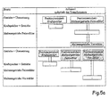
- FIG. 5a further embodiments of the invention are shown schematically.
- Figure 5a is shown for a location of the tap changer outside the transformer that a first torque motor according to the invention directly actuates the diverter switch, by making the previous power storage superfluous (left positioning unit);
- Another torque motor (right positioning unit) directly actuates the Geneva transmission of the fine selector and, if necessary, the preselector.
- Figure 4a and 4b in each of which only a single torque motor is provided, so here are several such positioning units with torque motor shown.
- a modified embodiment of the invention which provides a total of three such torque motors: a first positioning unit according to the invention (left) actuates directly - while avoiding a previous force accumulator - the diverter switch, a second positioning unit (middle) directly actuates the fine selector, and a third positioning unit (right) directly actuates the selection, if any.
- a first positioning unit according to the invention (left) actuates directly - while avoiding a previous force accumulator - the diverter switch
- a second positioning unit (middle) directly actuates the fine selector
- a third positioning unit (right) directly actuates the selection, if any.
- these embodiments of the invention are shown at a mounting location of the tap changer within the transformer.
- FIGS. 6a and 6b show, in the same schematic representation, possible embodiments of the invention in the case of a tap changer of the load selector type.
- FIG. 6a again relates to the arrangement of the tap-changer outside the transformer, FIG. 6b for one inside the transformer.
- the upper illustration in each case illustrates an embodiment in which a torque motor directly actuates the energy storage, which in turn rotates in a known manner, the switching column jumped and also optionally actuates the preselector.
- the middle diagram shows an embodiment of the invention, in which the torque motor also takes over the function of the previous energy storage and directly rotates the switching column jump.
- the lower illustration shows an embodiment with two separate torque motors, such that the first of these novel positioning units jumps directly over the switching column and the second positioning unit actuates an existing preselector separately.
- FIG. 9a is shown for an arrangement of the tap changer outside the transformer in the upper half of the illustration that here according to the invention a torque motor replaces the previous motor drive and acts directly on the drive shaft and the reversing gear. The drive shaft in turn then actuates in each phase again selection, fine selector, bypass contact and the energy storage device (not shown), the vacuum switching cell.
- a torque motor in each phase in each case a new positioning, which also includes the previous deflection gear, forms.
- FIG. 9b shows the corresponding arrangements for a tap changer arranged in the transformer.
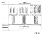
- FIGS. 10a and 10b again schematically illustrate further embodiments of the invention.
- a first torque motor means a gearbox at the same time preselector and fine selector operated and in each case a second torque motor the bypass contact and - again operated by the windable energy storage - the vacuum switching cell.
- a further embodiment of the invention is shown, which has a total of three such torque motors in each phase, which together with the corresponding gear form a separate positioning and directly each on the preselector or the fine or both the bypass switch and the energy storage of the vacuum switch cell Act.
- FIG. 10b again shows these embodiments for an arrangement of the tap changer in the transformer.
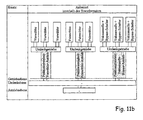
- FIGS. 11a and 11b modified embodiments of the invention are shown again.
- a first torque motor actuates the preselection of all three phases
- a second torque motor controls the fine-tuning of all two phases
- a third torque motor actuates both the bypass contacts and the energy storage and thus vacuum switching cells of all three phases.
- FIGS. 12a and 12b in the same schematic representation, possible embodiments of the invention are shown in a further known generic tap changer whose known prior art gear train has been illustrated in FIG. 8 and has already been explained.
- the upper representations each show an embodiment in which a single torque motor in each case via intermediate gearbox the preselector, the fine selector and at the same time bypass contact and vacuum switching cell, in turn via a force storage device operated.
- the underlying middle representations each show an embodiment in which two such torque motors are provided in each phase. One of them actuates both preselector and fine selector, the other both bypass contact and energy storage of the vacuum switching cell.
- each another variant is shown in which three torque motors are provided for actuation in each phase: one for the preselector, one for the fine selector, one for the bypass contact and the energy storage of the vacuum switch cell.
- three torque motors are provided for actuation in each phase: one for the preselector, one for the fine selector, one for the bypass contact and the energy storage of the vacuum switch cell.
Landscapes
- Engineering & Computer Science (AREA)
- Power Engineering (AREA)
- Housings And Mounting Of Transformers (AREA)
- Control Of Stepping Motors (AREA)
- Control Of Motors That Do Not Use Commutators (AREA)
- Separation By Low-Temperature Treatments (AREA)
- Use Of Switch Circuits For Exchanges And Methods Of Control Of Multiplex Exchanges (AREA)
- Ultra Sonic Daignosis Equipment (AREA)
- Connection Of Motors, Electrical Generators, Mechanical Devices, And The Like (AREA)
- Oscillators With Electromechanical Resonators (AREA)
- Control Of Electric Motors In General (AREA)
Applications Claiming Priority (5)
| Application Number | Priority Date | Filing Date | Title |
|---|---|---|---|
| DE10315207 | 2003-04-03 | ||
| DE10315206 | 2003-04-03 | ||
| DE2003115207 DE10315207A1 (de) | 2003-04-03 | 2003-04-03 | Stufenschalter |
| DE2003115206 DE10315206A1 (de) | 2003-04-03 | 2003-04-03 | Stufenschalter |
| PCT/EP2004/001648 WO2004088693A1 (de) | 2003-04-03 | 2004-02-20 | Stufenschalter |
Publications (2)
| Publication Number | Publication Date |
|---|---|
| EP1609162A1 EP1609162A1 (de) | 2005-12-28 |
| EP1609162B1 true EP1609162B1 (de) | 2006-10-04 |
Family
ID=33132674
Family Applications (1)
| Application Number | Title | Priority Date | Filing Date |
|---|---|---|---|
| EP04713013A Expired - Lifetime EP1609162B1 (de) | 2003-04-03 | 2004-02-20 | Stufenschalter |
Country Status (15)
| Country | Link |
|---|---|
| US (1) | US7463010B2 (pl) |
| EP (1) | EP1609162B1 (pl) |
| JP (1) | JP2006522470A (pl) |
| KR (1) | KR101096537B1 (pl) |
| CN (1) | CN100552847C (pl) |
| AT (1) | ATE341825T1 (pl) |
| BR (1) | BRPI0408538A (pl) |
| CA (1) | CA2520904C (pl) |
| DE (1) | DE502004001678D1 (pl) |
| ES (1) | ES2270348T3 (pl) |
| MX (1) | MXPA05010395A (pl) |
| PL (1) | PL205742B1 (pl) |
| RU (1) | RU2324994C2 (pl) |
| UA (1) | UA84417C2 (pl) |
| WO (1) | WO2004088693A1 (pl) |
Families Citing this family (29)
| Publication number | Priority date | Publication date | Assignee | Title |
|---|---|---|---|---|
| KR20090054967A (ko) * | 2006-08-25 | 2009-06-01 | 에이비비 테크놀로지 리미티드 | 부하시 탭 절환기용 전기 모터 드라이브 유닛 |
| DE202010011521U1 (de) | 2010-08-18 | 2011-11-23 | Maschinenfabrik Reinhausen Gmbh | Laststufenschalter |
| EP2482416B1 (en) * | 2011-01-31 | 2014-11-12 | Alstom Technology Ltd | On-load tap changer control method for a power excitation chain, related unit and power excitation chain comprising such unit |
| CN103548107B (zh) | 2011-03-27 | 2016-08-24 | Abb技术有限公司 | 具有改进的监视系统的抽头变换器 |
| DE102011111808B4 (de) * | 2011-08-27 | 2017-04-20 | Audi Ag | Trennadapter für einen Fahrzeugkomponententest und Testverfahren für eine Fahrzeugkomponente |
| DE202012101475U1 (de) * | 2012-04-20 | 2013-07-23 | Maschinenfabrik Reinhausen Gmbh | Laststufenschalter |
| DE202012101477U1 (de) * | 2012-04-20 | 2013-07-23 | Maschinenfabrik Reinhausen Gmbh | Laststufenschalter |
| DE202012101476U1 (de) * | 2012-04-20 | 2013-07-23 | Maschinenfabrik Reinhausen Gmbh | Laststufenschalter |
| DE102012103490B4 (de) * | 2012-04-20 | 2015-11-12 | Maschinenfabrik Reinhausen Gmbh | Verteiltransformator zur Spannungsregelung von Ortsnetzen |
| DE102012103489B4 (de) * | 2012-04-20 | 2015-11-12 | Maschinenfabrik Reinhausen Gmbh | Laststufenschalter und dessen Verwendung zur Spannungsregelung in einem Verteiltransformator |
| DE102012103736A1 (de) * | 2012-04-27 | 2013-10-31 | Maschinenfabrik Reinhausen Gmbh | Verfahren zur Funktionsüberwachung eines Stufenschalters |
| DE102012104089A1 (de) * | 2012-04-27 | 2013-10-31 | Maschinenfabrik Reinhausen Gmbh | Verfahren zur Ausmittelung eines Laststufenschalters |
| DE102012105152B4 (de) * | 2012-06-14 | 2015-11-12 | Maschinenfabrik Reinhausen Gmbh | Laststufenschalter zur unterbrechungslosen Umschaltung zwischen verschiedenen Wicklungsanzapfungen eines Stufentransformators |
| KR101348334B1 (ko) * | 2012-12-27 | 2014-01-09 | (주) 모노인더스트리 | 초고압 변압기용 무부하 탭절환기 |
| EP2973991A4 (en) | 2013-03-15 | 2016-11-30 | Cooper Technologies Co | CIRCUIT ARRANGEMENT FOR VOLTAGE REGULATOR |
| DE102013107558A1 (de) | 2013-07-16 | 2015-01-22 | Maschinenfabrik Reinhausen Gmbh | Laststufenschalter |
| KR101483066B1 (ko) * | 2013-07-23 | 2015-01-16 | (주) 모노인더스트리 | 배전용 30kv 무부하탭절환기 |
| DE102014100949B4 (de) * | 2014-01-28 | 2016-12-29 | Maschinenfabrik Reinhausen Gmbh | Laststufenschalter nach dem Reaktorschaltprinzip |
| DE102014012266B4 (de) * | 2014-08-22 | 2024-10-02 | Maschinenfabrik Reinhausen Gmbh | Schaltanordnung mit zwei Laststufenschaltern, elektrische Anlage mit einer derartigen Schaltanordnung sowie deren Verwendung |
| DE102016104499B3 (de) * | 2016-03-11 | 2017-04-27 | Maschinenfabrik Reinhausen Gmbh | Wähler für einen Laststufenschalter und Laststufenschalter mit Lastumschalter und Wähler |
| DE102016104500B3 (de) | 2016-03-11 | 2017-05-04 | Maschinenfabrik Reinhausen Gmbh | Laststufenschalter |
| US9679710B1 (en) | 2016-05-04 | 2017-06-13 | Cooper Technologies Company | Switching module controller for a voltage regulator |
| DE102019112721A1 (de) * | 2019-05-15 | 2020-11-19 | Maschinenfabrik Reinhausen Gmbh | Verfahren zum Durchführen einer Umschaltung von mindestens zwei Schaltmitteln eines Betriebsmittels und Antriebssystem für mindestens zwei Schaltmittel in einem Betriebsmittel |
| DE102019112717A1 (de) | 2019-05-15 | 2020-11-19 | Maschinenfabrik Reinhausen Gmbh | Antriebssystem für einen Schalter und ein Verfahren zum Antreiben eines Schalters |
| DE102019112720A1 (de) | 2019-05-15 | 2020-11-19 | Maschinenfabrik Reinhausen Gmbh | Verfahren zum Durchführen einer Umschaltung eines Schalters und Antriebssystem für einen Schalter |
| DE102019112718A1 (de) * | 2019-05-15 | 2020-11-19 | Maschinenfabrik Reinhausen Gmbh | Verfahren zum Durchführen einer Umschaltung von mindestens einem Schaltmittel eines Betriebsmittels und Antriebssystem für mindestens ein Schaltmittel eines Betriebsmittels |
| DE102019130462B4 (de) * | 2019-11-12 | 2022-03-24 | Maschinenfabrik Reinhausen Gmbh | Wähler für Laststufenschalter sowie Laststufenschalter damit |
| KR102219309B1 (ko) * | 2020-11-13 | 2021-02-24 | 한국에너지솔루션 주식회사 | 스마트 oltc 배전용 변압기 |
| DE102021116421A1 (de) * | 2021-06-25 | 2022-12-29 | Maschinenfabrik Reinhausen Gmbh | Schaltereinheit |
Family Cites Families (18)
| Publication number | Priority date | Publication date | Assignee | Title |
|---|---|---|---|---|
| DE474613C (de) * | 1926-07-13 | 1929-04-06 | Bernhard Jansen Dipl Ing Dr In | Einrichtung zum Umschalten zweier Anzapfungen eines Stufentransformators waehrend des Betriebes durch zwei gegenlaeufig bewegte Leistungsschalter mit Vorkontakten |
| GB419283A (en) * | 1933-03-06 | 1934-11-06 | Gen Electric Co Ltd | Improvements in or relating to tap changing apparatus for electric transformers |
| GB434884A (en) * | 1934-03-14 | 1935-09-11 | Gen Electric Co Ltd | Improvements in automatic voltage regulators |
| CH434467A (de) * | 1965-06-16 | 1967-04-30 | Heberlein & Co Ag | Elektromagnetischer Drehmomentgeber |
| SE402502B (sv) * | 1976-10-29 | 1978-07-03 | Asea Ab | Lindningskopplare |
| JPS56153718A (en) * | 1980-04-29 | 1981-11-27 | Mitsubishi Electric Corp | On-load tap changer |
| JPH01129314A (ja) * | 1987-11-16 | 1989-05-22 | Mitsubishi Electric Corp | タップ切換駆動装置 |
| CN2049981U (zh) * | 1989-03-29 | 1989-12-27 | 凌国胜 | 磁控直流电焊机 |
| DE4011019C1 (pl) * | 1990-04-05 | 1991-12-05 | Maschinenfabrik Reinhausen Gmbh, 8400 Regensburg, De | |
| JPH0628593A (ja) * | 1992-07-10 | 1994-02-04 | Takaoka Electric Mfg Co Ltd | 変圧器タップ位置遠隔監視装置 |
| HU220525B1 (hu) * | 1994-03-09 | 2002-03-28 | Maschinenfabrik Reinhausen Gmbh. | Kapcsolási elrendezés fokozatkapcsolók terhelésátkapcsolójához és terhelésválasztóhoz |
| JP3590671B2 (ja) * | 1995-05-23 | 2004-11-17 | ティーエム・ティーアンドディー株式会社 | 負荷時タップ切換装置 |
| DE19707548C1 (de) * | 1997-02-26 | 1998-06-18 | Reinhausen Maschf Scheubeck | Motorantrieb |
| DE19743864C1 (de) * | 1997-10-04 | 1999-04-15 | Reinhausen Maschf Scheubeck | Stufenschalter |
| DE19836463C1 (de) * | 1998-08-12 | 1999-10-21 | Reinhausen Maschf Scheubeck | Stufenschalter mit einem Vorwähler |
| DE10003918C1 (de) * | 2000-01-29 | 2001-07-05 | Reinhausen Maschf Scheubeck | Verfahren zur Überwachung des Kontaktabbrandes bei Stufenschaltern |
| JP2001267149A (ja) * | 2000-03-21 | 2001-09-28 | Mitsubishi Electric Corp | タップ切換装置 |
| JP4406176B2 (ja) * | 2001-06-07 | 2010-01-27 | 株式会社東芝 | 洗濯機 |
-
2004
- 2004-02-20 AT AT04713013T patent/ATE341825T1/de active
- 2004-02-20 KR KR1020057017158A patent/KR101096537B1/ko not_active Expired - Fee Related
- 2004-02-20 PL PL378683A patent/PL205742B1/pl not_active IP Right Cessation
- 2004-02-20 US US10/551,600 patent/US7463010B2/en not_active Expired - Fee Related
- 2004-02-20 MX MXPA05010395A patent/MXPA05010395A/es active IP Right Grant
- 2004-02-20 DE DE502004001678T patent/DE502004001678D1/de not_active Expired - Lifetime
- 2004-02-20 CA CA2520904A patent/CA2520904C/en not_active Expired - Fee Related
- 2004-02-20 ES ES04713013T patent/ES2270348T3/es not_active Expired - Lifetime
- 2004-02-20 JP JP2006504437A patent/JP2006522470A/ja active Pending
- 2004-02-20 BR BRPI0408538-8A patent/BRPI0408538A/pt not_active Application Discontinuation
- 2004-02-20 CN CNB2004800071336A patent/CN100552847C/zh not_active Expired - Fee Related
- 2004-02-20 WO PCT/EP2004/001648 patent/WO2004088693A1/de not_active Ceased
- 2004-02-20 UA UAA200509235A patent/UA84417C2/uk unknown
- 2004-02-20 EP EP04713013A patent/EP1609162B1/de not_active Expired - Lifetime
- 2004-02-20 RU RU2005134008/09A patent/RU2324994C2/ru not_active IP Right Cessation
Also Published As
| Publication number | Publication date |
|---|---|
| RU2005134008A (ru) | 2006-03-20 |
| BRPI0408538A (pt) | 2006-03-07 |
| PL205742B1 (pl) | 2010-05-31 |
| CN1809905A (zh) | 2006-07-26 |
| KR101096537B1 (ko) | 2011-12-20 |
| RU2324994C2 (ru) | 2008-05-20 |
| ATE341825T1 (de) | 2006-10-15 |
| HK1085837A1 (en) | 2006-09-01 |
| CA2520904A1 (en) | 2004-10-14 |
| WO2004088693A1 (de) | 2004-10-14 |
| EP1609162A1 (de) | 2005-12-28 |
| JP2006522470A (ja) | 2006-09-28 |
| KR20050116145A (ko) | 2005-12-09 |
| MXPA05010395A (es) | 2005-11-08 |
| US20060244431A1 (en) | 2006-11-02 |
| UA84417C2 (uk) | 2008-10-27 |
| PL378683A1 (pl) | 2006-05-15 |
| US7463010B2 (en) | 2008-12-09 |
| CN100552847C (zh) | 2009-10-21 |
| DE502004001678D1 (de) | 2006-11-16 |
| CA2520904C (en) | 2013-09-10 |
| ES2270348T3 (es) | 2007-04-01 |
Similar Documents
| Publication | Publication Date | Title |
|---|---|---|
| EP1609162B1 (de) | Stufenschalter | |
| DE102012105152B4 (de) | Laststufenschalter zur unterbrechungslosen Umschaltung zwischen verschiedenen Wicklungsanzapfungen eines Stufentransformators | |
| EP3427284B1 (de) | Laststufenschalter | |
| DE102012103490B4 (de) | Verteiltransformator zur Spannungsregelung von Ortsnetzen | |
| DE102016117526B3 (de) | Lasststufenschalter, Regeltransformator mit Laststufenschalter und Verfahren zum Schalten eines Laststufenschalters | |
| EP2839491B1 (de) | Laststufenschalter | |
| EP2839495B1 (de) | Laststufenschalter | |
| EP2839492B1 (de) | Laststufenschalter | |
| EP0749627A1 (de) | Umschaltanordnung für lastumschalter von stufenschaltern und für lastwähler | |
| DE19847745C1 (de) | Stufenschalter | |
| WO2013174568A1 (de) | Anordnung von vakuumschaltröhren bei einem lastumschalter | |
| DE4407945C1 (de) | Umschaltanordnung für Lastumschalter und für Lastwähler | |
| EP2839493B1 (de) | Laststufenschalter | |
| EP2421014A1 (de) | Stufenschalter | |
| DE10315206A1 (de) | Stufenschalter | |
| DE102013109289A1 (de) | Laststufenschalter, Stufentransformator zur Spannungsregelung und Verfahren zur Durchführung einer Umschaltung im Stufentransformator | |
| WO2013010699A1 (de) | Verfahren zur lastumschaltung und lastumschalter für einen stufenschalter | |
| DE2201937B1 (de) | Anordnung zur spannungsregelung von stufentransformatoren | |
| DE10315207A1 (de) | Stufenschalter | |
| EP1380041A1 (de) | Lastwähler | |
| EP0763835A2 (de) | Stufenwähler | |
| AT162525B (de) | Stufenschalterantrieb |
Legal Events
| Date | Code | Title | Description |
|---|---|---|---|
| PUAI | Public reference made under article 153(3) epc to a published international application that has entered the european phase |
Free format text: ORIGINAL CODE: 0009012 |
|
| 17P | Request for examination filed |
Effective date: 20050722 |
|
| AK | Designated contracting states |
Kind code of ref document: A1 Designated state(s): AT BE BG CH CY CZ DE DK EE ES FI FR GB GR HU IE IT LI LU MC NL PT RO SE SI SK TR |
|
| AX | Request for extension of the european patent |
Extension state: AL LT LV MK |
|
| GRAP | Despatch of communication of intention to grant a patent |
Free format text: ORIGINAL CODE: EPIDOSNIGR1 |
|
| GRAS | Grant fee paid |
Free format text: ORIGINAL CODE: EPIDOSNIGR3 |
|
| DAX | Request for extension of the european patent (deleted) | ||
| GRAA | (expected) grant |
Free format text: ORIGINAL CODE: 0009210 |
|
| REG | Reference to a national code |
Ref country code: HK Ref legal event code: DE Ref document number: 1085837 Country of ref document: HK |
|
| AK | Designated contracting states |
Kind code of ref document: B1 Designated state(s): AT BE BG CH CY CZ DE DK EE ES FI FR GB GR HU IE IT LI LU MC NL PT RO SE SI SK TR |
|
| PG25 | Lapsed in a contracting state [announced via postgrant information from national office to epo] |
Ref country code: IT Free format text: LAPSE BECAUSE OF FAILURE TO SUBMIT A TRANSLATION OF THE DESCRIPTION OR TO PAY THE FEE WITHIN THE PRESCRIBED TIME-LIMIT;WARNING: LAPSES OF ITALIAN PATENTS WITH EFFECTIVE DATE BEFORE 2007 MAY HAVE OCCURRED AT ANY TIME BEFORE 2007. THE CORRECT EFFECTIVE DATE MAY BE DIFFERENT FROM THE ONE RECORDED. Effective date: 20061004 Ref country code: NL Free format text: LAPSE BECAUSE OF FAILURE TO SUBMIT A TRANSLATION OF THE DESCRIPTION OR TO PAY THE FEE WITHIN THE PRESCRIBED TIME-LIMIT Effective date: 20061004 Ref country code: SK Free format text: LAPSE BECAUSE OF FAILURE TO SUBMIT A TRANSLATION OF THE DESCRIPTION OR TO PAY THE FEE WITHIN THE PRESCRIBED TIME-LIMIT Effective date: 20061004 Ref country code: IE Free format text: LAPSE BECAUSE OF FAILURE TO SUBMIT A TRANSLATION OF THE DESCRIPTION OR TO PAY THE FEE WITHIN THE PRESCRIBED TIME-LIMIT Effective date: 20061004 Ref country code: CZ Free format text: LAPSE BECAUSE OF FAILURE TO SUBMIT A TRANSLATION OF THE DESCRIPTION OR TO PAY THE FEE WITHIN THE PRESCRIBED TIME-LIMIT Effective date: 20061004 Ref country code: SI Free format text: LAPSE BECAUSE OF FAILURE TO SUBMIT A TRANSLATION OF THE DESCRIPTION OR TO PAY THE FEE WITHIN THE PRESCRIBED TIME-LIMIT Effective date: 20061004 Ref country code: FI Free format text: LAPSE BECAUSE OF FAILURE TO SUBMIT A TRANSLATION OF THE DESCRIPTION OR TO PAY THE FEE WITHIN THE PRESCRIBED TIME-LIMIT Effective date: 20061004 |
|
| REG | Reference to a national code |
Ref country code: GB Ref legal event code: FG4D Free format text: NOT ENGLISH |
|
| GBT | Gb: translation of ep patent filed (gb section 77(6)(a)/1977) |
Effective date: 20061004 |
|
| REG | Reference to a national code |
Ref country code: CH Ref legal event code: EP |
|
| REG | Reference to a national code |
Ref country code: IE Ref legal event code: FG4D Free format text: LANGUAGE OF EP DOCUMENT: GERMAN |
|
| REF | Corresponds to: |
Ref document number: 502004001678 Country of ref document: DE Date of ref document: 20061116 Kind code of ref document: P |
|
| REG | Reference to a national code |
Ref country code: RO Ref legal event code: EPE |
|
| REG | Reference to a national code |
Ref country code: SE Ref legal event code: TRGR |
|
| PG25 | Lapsed in a contracting state [announced via postgrant information from national office to epo] |
Ref country code: DK Free format text: LAPSE BECAUSE OF FAILURE TO SUBMIT A TRANSLATION OF THE DESCRIPTION OR TO PAY THE FEE WITHIN THE PRESCRIBED TIME-LIMIT Effective date: 20070104 |
|
| PG25 | Lapsed in a contracting state [announced via postgrant information from national office to epo] |
Ref country code: MC Free format text: LAPSE BECAUSE OF NON-PAYMENT OF DUE FEES Effective date: 20070228 |
|
| PG25 | Lapsed in a contracting state [announced via postgrant information from national office to epo] |
Ref country code: PT Free format text: LAPSE BECAUSE OF FAILURE TO SUBMIT A TRANSLATION OF THE DESCRIPTION OR TO PAY THE FEE WITHIN THE PRESCRIBED TIME-LIMIT Effective date: 20070316 |
|
| REG | Reference to a national code |
Ref country code: ES Ref legal event code: FG2A Ref document number: 2270348 Country of ref document: ES Kind code of ref document: T3 |
|
| NLV1 | Nl: lapsed or annulled due to failure to fulfill the requirements of art. 29p and 29m of the patents act | ||
| ET | Fr: translation filed | ||
| REG | Reference to a national code |
Ref country code: HK Ref legal event code: WD Ref document number: 1085837 Country of ref document: HK |
|
| REG | Reference to a national code |
Ref country code: IE Ref legal event code: FD4D |
|
| REG | Reference to a national code |
Ref country code: HK Ref legal event code: GR Ref document number: 1085837 Country of ref document: HK |
|
| PLBE | No opposition filed within time limit |
Free format text: ORIGINAL CODE: 0009261 |
|
| STAA | Information on the status of an ep patent application or granted ep patent |
Free format text: STATUS: NO OPPOSITION FILED WITHIN TIME LIMIT |
|
| 26N | No opposition filed |
Effective date: 20070705 |
|
| BERE | Be: lapsed |
Owner name: MASCHINENFABRIK REINHAUSEN G.M.B.H. Effective date: 20070228 |
|
| PG25 | Lapsed in a contracting state [announced via postgrant information from national office to epo] |
Ref country code: BE Free format text: LAPSE BECAUSE OF NON-PAYMENT OF DUE FEES Effective date: 20070228 |
|
| PG25 | Lapsed in a contracting state [announced via postgrant information from national office to epo] |
Ref country code: GR Free format text: LAPSE BECAUSE OF FAILURE TO SUBMIT A TRANSLATION OF THE DESCRIPTION OR TO PAY THE FEE WITHIN THE PRESCRIBED TIME-LIMIT Effective date: 20070105 |
|
| PG25 | Lapsed in a contracting state [announced via postgrant information from national office to epo] |
Ref country code: EE Free format text: LAPSE BECAUSE OF FAILURE TO SUBMIT A TRANSLATION OF THE DESCRIPTION OR TO PAY THE FEE WITHIN THE PRESCRIBED TIME-LIMIT Effective date: 20061004 |
|
| REG | Reference to a national code |
Ref country code: CH Ref legal event code: PL |
|
| PG25 | Lapsed in a contracting state [announced via postgrant information from national office to epo] |
Ref country code: LI Free format text: LAPSE BECAUSE OF NON-PAYMENT OF DUE FEES Effective date: 20080229 Ref country code: CH Free format text: LAPSE BECAUSE OF NON-PAYMENT OF DUE FEES Effective date: 20080229 |
|
| PG25 | Lapsed in a contracting state [announced via postgrant information from national office to epo] |
Ref country code: LU Free format text: LAPSE BECAUSE OF NON-PAYMENT OF DUE FEES Effective date: 20070220 Ref country code: CY Free format text: LAPSE BECAUSE OF FAILURE TO SUBMIT A TRANSLATION OF THE DESCRIPTION OR TO PAY THE FEE WITHIN THE PRESCRIBED TIME-LIMIT Effective date: 20061004 |
|
| PG25 | Lapsed in a contracting state [announced via postgrant information from national office to epo] |
Ref country code: HU Free format text: LAPSE BECAUSE OF FAILURE TO SUBMIT A TRANSLATION OF THE DESCRIPTION OR TO PAY THE FEE WITHIN THE PRESCRIBED TIME-LIMIT Effective date: 20070405 Ref country code: TR Free format text: LAPSE BECAUSE OF FAILURE TO SUBMIT A TRANSLATION OF THE DESCRIPTION OR TO PAY THE FEE WITHIN THE PRESCRIBED TIME-LIMIT Effective date: 20061004 |
|
| PGFP | Annual fee paid to national office [announced via postgrant information from national office to epo] |
Ref country code: ES Payment date: 20130208 Year of fee payment: 10 Ref country code: RO Payment date: 20130212 Year of fee payment: 10 |
|
| PGFP | Annual fee paid to national office [announced via postgrant information from national office to epo] |
Ref country code: AT Payment date: 20130204 Year of fee payment: 10 |
|
| REG | Reference to a national code |
Ref country code: AT Ref legal event code: MM01 Ref document number: 341825 Country of ref document: AT Kind code of ref document: T Effective date: 20140220 |
|
| PG25 | Lapsed in a contracting state [announced via postgrant information from national office to epo] |
Ref country code: RO Free format text: LAPSE BECAUSE OF NON-PAYMENT OF DUE FEES Effective date: 20140220 |
|
| PG25 | Lapsed in a contracting state [announced via postgrant information from national office to epo] |
Ref country code: AT Free format text: LAPSE BECAUSE OF NON-PAYMENT OF DUE FEES Effective date: 20140220 |
|
| REG | Reference to a national code |
Ref country code: ES Ref legal event code: FD2A Effective date: 20150327 |
|
| PG25 | Lapsed in a contracting state [announced via postgrant information from national office to epo] |
Ref country code: ES Free format text: LAPSE BECAUSE OF NON-PAYMENT OF DUE FEES Effective date: 20140221 |
|
| REG | Reference to a national code |
Ref country code: FR Ref legal event code: PLFP Year of fee payment: 13 |
|
| REG | Reference to a national code |
Ref country code: FR Ref legal event code: PLFP Year of fee payment: 14 |
|
| REG | Reference to a national code |
Ref country code: FR Ref legal event code: PLFP Year of fee payment: 15 |
|
| PGFP | Annual fee paid to national office [announced via postgrant information from national office to epo] |
Ref country code: GB Payment date: 20190221 Year of fee payment: 16 Ref country code: DE Payment date: 20190219 Year of fee payment: 16 |
|
| PGFP | Annual fee paid to national office [announced via postgrant information from national office to epo] |
Ref country code: SE Payment date: 20190221 Year of fee payment: 16 Ref country code: FR Payment date: 20190221 Year of fee payment: 16 |
|
| PGFP | Annual fee paid to national office [announced via postgrant information from national office to epo] |
Ref country code: BG Payment date: 20190218 Year of fee payment: 16 |
|
| REG | Reference to a national code |
Ref country code: DE Ref legal event code: R119 Ref document number: 502004001678 Country of ref document: DE |
|
| REG | Reference to a national code |
Ref country code: SE Ref legal event code: EUG |
|
| GBPC | Gb: european patent ceased through non-payment of renewal fee |
Effective date: 20200220 |
|
| PG25 | Lapsed in a contracting state [announced via postgrant information from national office to epo] |
Ref country code: SE Free format text: LAPSE BECAUSE OF NON-PAYMENT OF DUE FEES Effective date: 20200221 |
|
| PG25 | Lapsed in a contracting state [announced via postgrant information from national office to epo] |
Ref country code: BG Free format text: LAPSE BECAUSE OF NON-PAYMENT OF DUE FEES Effective date: 20200831 |
|
| PG25 | Lapsed in a contracting state [announced via postgrant information from national office to epo] |
Ref country code: DE Free format text: LAPSE BECAUSE OF NON-PAYMENT OF DUE FEES Effective date: 20200901 Ref country code: FR Free format text: LAPSE BECAUSE OF NON-PAYMENT OF DUE FEES Effective date: 20200229 Ref country code: GB Free format text: LAPSE BECAUSE OF NON-PAYMENT OF DUE FEES Effective date: 20200220 |