EP1609597A2 - Laminator zum Herstellen von Schichtkörpern - Google Patents
Laminator zum Herstellen von Schichtkörpern Download PDFInfo
- Publication number
- EP1609597A2 EP1609597A2 EP05011970A EP05011970A EP1609597A2 EP 1609597 A2 EP1609597 A2 EP 1609597A2 EP 05011970 A EP05011970 A EP 05011970A EP 05011970 A EP05011970 A EP 05011970A EP 1609597 A2 EP1609597 A2 EP 1609597A2
- Authority
- EP
- European Patent Office
- Prior art keywords
- laminating
- laminator
- laminated
- laminator according
- component
- Prior art date
- Legal status (The legal status is an assumption and is not a legal conclusion. Google has not performed a legal analysis and makes no representation as to the accuracy of the status listed.)
- Withdrawn
Links
Images


Classifications
-
- B—PERFORMING OPERATIONS; TRANSPORTING
- B30—PRESSES
- B30B—PRESSES IN GENERAL
- B30B5/00—Presses characterised by the use of pressing means other than those mentioned in the preceding groups
- B30B5/02—Presses characterised by the use of pressing means other than those mentioned in the preceding groups wherein the pressing means is in the form of a flexible element, e.g. diaphragm, urged by fluid pressure
-
- B—PERFORMING OPERATIONS; TRANSPORTING
- B29—WORKING OF PLASTICS; WORKING OF SUBSTANCES IN A PLASTIC STATE IN GENERAL
- B29C—SHAPING OR JOINING OF PLASTICS; SHAPING OF MATERIAL IN A PLASTIC STATE, NOT OTHERWISE PROVIDED FOR; AFTER-TREATMENT OF THE SHAPED PRODUCTS, e.g. REPAIRING
- B29C43/00—Compression moulding, i.e. applying external pressure to flow the moulding material; Apparatus therefor
- B29C43/32—Component parts, details or accessories; Auxiliary operations
- B29C43/56—Compression moulding under special conditions, e.g. vacuum
-
- B—PERFORMING OPERATIONS; TRANSPORTING
- B30—PRESSES
- B30B—PRESSES IN GENERAL
- B30B7/00—Presses characterised by a particular arrangement of the pressing members
- B30B7/02—Presses characterised by a particular arrangement of the pressing members having several platens arranged one above the other
- B30B7/023—Feeding or discharging means
-
- B—PERFORMING OPERATIONS; TRANSPORTING
- B32—LAYERED PRODUCTS
- B32B—LAYERED PRODUCTS, i.e. PRODUCTS BUILT-UP OF STRATA OF FLAT OR NON-FLAT, e.g. CELLULAR OR HONEYCOMB, FORM
- B32B17/00—Layered products essentially comprising sheet glass, or glass, slag, or like fibres
- B32B17/06—Layered products essentially comprising sheet glass, or glass, slag, or like fibres comprising glass as the main or only constituent of a layer, next to another layer of a specific material
- B32B17/10—Layered products essentially comprising sheet glass, or glass, slag, or like fibres comprising glass as the main or only constituent of a layer, next to another layer of a specific material of synthetic resin
- B32B17/10005—Layered products essentially comprising sheet glass, or glass, slag, or like fibres comprising glass as the main or only constituent of a layer, next to another layer of a specific material of synthetic resin laminated safety glass or glazing
- B32B17/10807—Making laminated safety glass or glazing; Apparatus therefor
- B32B17/10816—Making laminated safety glass or glazing; Apparatus therefor by pressing
- B32B17/10825—Isostatic pressing, i.e. using non rigid pressure-exerting members against rigid parts
- B32B17/10834—Isostatic pressing, i.e. using non rigid pressure-exerting members against rigid parts using a fluid
-
- B—PERFORMING OPERATIONS; TRANSPORTING
- B32—LAYERED PRODUCTS
- B32B—LAYERED PRODUCTS, i.e. PRODUCTS BUILT-UP OF STRATA OF FLAT OR NON-FLAT, e.g. CELLULAR OR HONEYCOMB, FORM
- B32B17/00—Layered products essentially comprising sheet glass, or glass, slag, or like fibres
- B32B17/06—Layered products essentially comprising sheet glass, or glass, slag, or like fibres comprising glass as the main or only constituent of a layer, next to another layer of a specific material
- B32B17/10—Layered products essentially comprising sheet glass, or glass, slag, or like fibres comprising glass as the main or only constituent of a layer, next to another layer of a specific material of synthetic resin
- B32B17/10005—Layered products essentially comprising sheet glass, or glass, slag, or like fibres comprising glass as the main or only constituent of a layer, next to another layer of a specific material of synthetic resin laminated safety glass or glazing
- B32B17/10807—Making laminated safety glass or glazing; Apparatus therefor
- B32B17/1088—Making laminated safety glass or glazing; Apparatus therefor by superposing a plurality of layered products
-
- B—PERFORMING OPERATIONS; TRANSPORTING
- B32—LAYERED PRODUCTS
- B32B—LAYERED PRODUCTS, i.e. PRODUCTS BUILT-UP OF STRATA OF FLAT OR NON-FLAT, e.g. CELLULAR OR HONEYCOMB, FORM
- B32B37/00—Methods or apparatus for laminating, e.g. by curing or by ultrasonic bonding
- B32B37/0046—Methods or apparatus for laminating, e.g. by curing or by ultrasonic bonding characterised by constructional aspects of the apparatus
-
- B—PERFORMING OPERATIONS; TRANSPORTING
- B32—LAYERED PRODUCTS
- B32B—LAYERED PRODUCTS, i.e. PRODUCTS BUILT-UP OF STRATA OF FLAT OR NON-FLAT, e.g. CELLULAR OR HONEYCOMB, FORM
- B32B37/00—Methods or apparatus for laminating, e.g. by curing or by ultrasonic bonding
- B32B37/10—Methods or apparatus for laminating, e.g. by curing or by ultrasonic bonding characterised by the pressing technique, e.g. using action of vacuum or fluid pressure
- B32B37/1009—Methods or apparatus for laminating, e.g. by curing or by ultrasonic bonding characterised by the pressing technique, e.g. using action of vacuum or fluid pressure using vacuum and fluid pressure
-
- B—PERFORMING OPERATIONS; TRANSPORTING
- B29—WORKING OF PLASTICS; WORKING OF SUBSTANCES IN A PLASTIC STATE IN GENERAL
- B29C—SHAPING OR JOINING OF PLASTICS; SHAPING OF MATERIAL IN A PLASTIC STATE, NOT OTHERWISE PROVIDED FOR; AFTER-TREATMENT OF THE SHAPED PRODUCTS, e.g. REPAIRING
- B29C43/00—Compression moulding, i.e. applying external pressure to flow the moulding material; Apparatus therefor
- B29C43/32—Component parts, details or accessories; Auxiliary operations
- B29C43/34—Feeding the material to the mould or the compression means
- B29C2043/3405—Feeding the material to the mould or the compression means using carrying means
- B29C2043/3411—Feeding the material to the mould or the compression means using carrying means mounted onto arms, e.g. grippers, fingers, clamping frame, suction means
-
- B—PERFORMING OPERATIONS; TRANSPORTING
- B29—WORKING OF PLASTICS; WORKING OF SUBSTANCES IN A PLASTIC STATE IN GENERAL
- B29C—SHAPING OR JOINING OF PLASTICS; SHAPING OF MATERIAL IN A PLASTIC STATE, NOT OTHERWISE PROVIDED FOR; AFTER-TREATMENT OF THE SHAPED PRODUCTS, e.g. REPAIRING
- B29C43/00—Compression moulding, i.e. applying external pressure to flow the moulding material; Apparatus therefor
- B29C43/32—Component parts, details or accessories; Auxiliary operations
- B29C43/34—Feeding the material to the mould or the compression means
- B29C2043/3405—Feeding the material to the mould or the compression means using carrying means
- B29C2043/3416—Feeding the material to the mould or the compression means using carrying means conveyor belts
-
- B—PERFORMING OPERATIONS; TRANSPORTING
- B29—WORKING OF PLASTICS; WORKING OF SUBSTANCES IN A PLASTIC STATE IN GENERAL
- B29C—SHAPING OR JOINING OF PLASTICS; SHAPING OF MATERIAL IN A PLASTIC STATE, NOT OTHERWISE PROVIDED FOR; AFTER-TREATMENT OF THE SHAPED PRODUCTS, e.g. REPAIRING
- B29C43/00—Compression moulding, i.e. applying external pressure to flow the moulding material; Apparatus therefor
- B29C43/32—Component parts, details or accessories; Auxiliary operations
- B29C43/36—Moulds for making articles of definite length, i.e. discrete articles
- B29C43/3642—Bags, bleeder sheets or cauls for isostatic pressing
- B29C2043/3647—Membranes, diaphragms
-
- B—PERFORMING OPERATIONS; TRANSPORTING
- B29—WORKING OF PLASTICS; WORKING OF SUBSTANCES IN A PLASTIC STATE IN GENERAL
- B29C—SHAPING OR JOINING OF PLASTICS; SHAPING OF MATERIAL IN A PLASTIC STATE, NOT OTHERWISE PROVIDED FOR; AFTER-TREATMENT OF THE SHAPED PRODUCTS, e.g. REPAIRING
- B29C43/00—Compression moulding, i.e. applying external pressure to flow the moulding material; Apparatus therefor
- B29C43/32—Component parts, details or accessories; Auxiliary operations
- B29C43/56—Compression moulding under special conditions, e.g. vacuum
- B29C2043/561—Compression moulding under special conditions, e.g. vacuum under vacuum conditions
- B29C2043/562—Compression moulding under special conditions, e.g. vacuum under vacuum conditions combined with isostatic pressure, e.g. pressurising fluids, gases
-
- B—PERFORMING OPERATIONS; TRANSPORTING
- B29—WORKING OF PLASTICS; WORKING OF SUBSTANCES IN A PLASTIC STATE IN GENERAL
- B29C—SHAPING OR JOINING OF PLASTICS; SHAPING OF MATERIAL IN A PLASTIC STATE, NOT OTHERWISE PROVIDED FOR; AFTER-TREATMENT OF THE SHAPED PRODUCTS, e.g. REPAIRING
- B29C43/00—Compression moulding, i.e. applying external pressure to flow the moulding material; Apparatus therefor
- B29C43/32—Component parts, details or accessories; Auxiliary operations
- B29C43/58—Measuring, controlling or regulating
- B29C2043/5833—Measuring, controlling or regulating movement of moulds or mould parts, e.g. opening or closing, actuating
- B29C2043/5841—Measuring, controlling or regulating movement of moulds or mould parts, e.g. opening or closing, actuating for accommodating variation in mould spacing or cavity volume during moulding
-
- B—PERFORMING OPERATIONS; TRANSPORTING
- B29—WORKING OF PLASTICS; WORKING OF SUBSTANCES IN A PLASTIC STATE IN GENERAL
- B29C—SHAPING OR JOINING OF PLASTICS; SHAPING OF MATERIAL IN A PLASTIC STATE, NOT OTHERWISE PROVIDED FOR; AFTER-TREATMENT OF THE SHAPED PRODUCTS, e.g. REPAIRING
- B29C33/00—Moulds or cores; Details thereof or accessories therefor
- B29C33/0088—Multi-face stack moulds
-
- B—PERFORMING OPERATIONS; TRANSPORTING
- B29—WORKING OF PLASTICS; WORKING OF SUBSTANCES IN A PLASTIC STATE IN GENERAL
- B29C—SHAPING OR JOINING OF PLASTICS; SHAPING OF MATERIAL IN A PLASTIC STATE, NOT OTHERWISE PROVIDED FOR; AFTER-TREATMENT OF THE SHAPED PRODUCTS, e.g. REPAIRING
- B29C33/00—Moulds or cores; Details thereof or accessories therefor
- B29C33/10—Moulds or cores; Details thereof or accessories therefor with incorporated venting means
-
- B—PERFORMING OPERATIONS; TRANSPORTING
- B29—WORKING OF PLASTICS; WORKING OF SUBSTANCES IN A PLASTIC STATE IN GENERAL
- B29C—SHAPING OR JOINING OF PLASTICS; SHAPING OF MATERIAL IN A PLASTIC STATE, NOT OTHERWISE PROVIDED FOR; AFTER-TREATMENT OF THE SHAPED PRODUCTS, e.g. REPAIRING
- B29C43/00—Compression moulding, i.e. applying external pressure to flow the moulding material; Apparatus therefor
- B29C43/32—Component parts, details or accessories; Auxiliary operations
-
- B—PERFORMING OPERATIONS; TRANSPORTING
- B29—WORKING OF PLASTICS; WORKING OF SUBSTANCES IN A PLASTIC STATE IN GENERAL
- B29L—INDEXING SCHEME ASSOCIATED WITH SUBCLASS B29C, RELATING TO PARTICULAR ARTICLES
- B29L2031/00—Other particular articles
- B29L2031/772—Articles characterised by their shape and not otherwise provided for
-
- B—PERFORMING OPERATIONS; TRANSPORTING
- B32—LAYERED PRODUCTS
- B32B—LAYERED PRODUCTS, i.e. PRODUCTS BUILT-UP OF STRATA OF FLAT OR NON-FLAT, e.g. CELLULAR OR HONEYCOMB, FORM
- B32B2457/00—Electrical equipment
- B32B2457/12—Photovoltaic modules
Definitions
- the present invention relates to a laminator for Manufacture of laminates consisting of at least a laminating chamber having a plurality of tiers arranged therein heated laminating plates, taking on each Laminating each one or more layers of laminate are weldable with a component and wherein the laminator Means for applying a pressing force to the components and the laminate layers during the lamination process having.
- a multi-plate press for making laminates with the above features is from the document DE-A-37 25 007 known.
- the disadvantage of this press that they only for absolutely flat and flat, leaf-shaped Laminate is suitable because the plates only flat laminates with flat over its surface constant thickness can press.
- This is the press in their applications very limited; in particular the manufacturing of inevitably uneven photovoltaic in their surface Solar cell modules or non-planar, i.e. e.g. domed, laminated glass is with this known press not possible.
- laminators are from the practice of lamination known from components.
- solar cell modules e.g.
- laminators are from the practice of lamination known from components.
- solar cell modules e.g. a plurality of semiconductor wafers and associated electrical conductors and at least one glass sheet and one or more thermoplastic transparent films with each other the lamination permanently connected.
- a concrete laminator is known from DE 33 00 622 C2.
- This known laminator has a single horizontal aligned heating plate, whose area to the surface a component to be laminated is adapted.
- disadvantageous to look at these known laminators that they consume a large area for their installation, when a high lamination capacity is achieved should. This often leads to the problem that subsequent Capacity increases only by new construction of additional Buildings for the installation of additional laminators are possible, which leads to high investment costs.
- EP 0 825 654 A2 discloses a continuous laminating system known for the production of solar cell modules, the solves the space problem described above.
- Laminate layers are on a lamination with Pressing applied and then there are several Laminating plates stacked in an oven with a door simultaneously laminated.
- the Task a laminator of the type mentioned above create, with low energy and space consumption a greater freedom in terms of the shape of the to be laminated Components as well as a high laminating capacity with offers a fast production cycle.
- the laminator according to the invention it is achieved that several components each on its own laminating plate one above the other using an appropriate number be laminated by pressing devices simultaneously can. Because every laminating plate and thus every one to be laminated Component own pressure device in the form each associated with a membrane, the components are each individually pressed, with each membrane easily adapts to the surface of the component, also and especially if the component in its surface is uneven. With each membrane can be a produce even pressure force over larger areas. At the same time, the size of the pressing force can be by the choice of the ruling in the membrane chamber Printing for each laminating individually and very accurate and varying widely as needed to adjust; So it can be done in a lamination cycle in the laminator simultaneously laminated different components which are e.g.
- the laminator of the invention many laminations at the same time, is a fast production cycle with a high flexibility in terms of different Achieved components.
- the installation surface for the laminator is practically no bigger than a conventional one Laminator with a single laminating plate. This can be an available installation space use in a building much more effectively, because too the height of a building for the installation of the laminator is being used.
- the laminating chamber by at least one lid or a door can be opened and closed and closed Condition airtight and to carry out a Laminating process under vacuum is evacuated.
- a so executed laminator can also lamination perform where a vacuum is necessary or makes sense, for example, to include bubbles safely exclude between the component and the laminate layers.
- a preferred development of the previously described laminator provides that all laminating and pressing devices in a single common laminating chamber are arranged.
- the construction of the laminating chamber becomes easy held, as they all laminating and pressing devices encloses. With this laminator can then all simultaneous laminating either all under vacuum or all under atmospheric conditions Air pressure, as needed, to be performed.
- the common Laminating chamber formed by a vacuum cabinet, in the laminating arranged in a horizontal orientation are and on the at least one side wall as adjustable door is formed.
- This version presents a favorable constructive solution.
- the loading of the Laminators with components to be laminated and unloading the laminated components from the laminator is advantageous easy to carry out, since the at least one Sidewall is designed as an adjustable door. So is a large-scale access to the interior of the vacuum cabinet given for loading and unloading.
- the laminator can be designed for manual use Loading and unloading be provided, in which case operating personnel the components to be laminated together with the laminate layers in the laminator inserts and after laminating the finished laminated components removed from the laminator.
- the laminating vertically guided are and between a divergent Position for feeding the components and the laminate layers and for discharging the laminated components on the one hand and a position taken together for the Laminating be moved on the other hand.
- the vertical one Mobility of laminating allows a cheap Operation of the laminator, as for loading and unloading the laminating plates moved apart and for the Laminating can be driven together.
- each laminating has its own plate frame for its holder, each in turn in one in the laminating chamber arranged guide frame, the vertical mobility the lamination allows, guided and held is.
- each of the laminating comprises or comprises at least one heating plate.
- each of the laminating comprises or comprises at least one heating plate.
- the heating plate each at the top and the pressing device respectively is arranged on the underside of the laminating plate and that in the collapsed state of laminating by means of the pressing device in each case towards the heating plate of the underlying laminating the Pressing force is exercisable.
- the heating plates in proportion each lie down to the pressing device, whereby the components to be laminated first for heating the heating plates can be placed. After the collision the laminating plates can then the pressing devices the pressure required for the lamination process on the components and their laminate layers against exercise the heating plates.
- the heating plates and the pressing devices are in the assembled state of laminating plates fixed relative to each other, so that the pressing devices get support in this way, the lifting of the laminating plates from each other by the forces exerted by the pressing devices prevented.
- each membrane is at its periphery with a circumferential edge profile is provided, wherein the Edge profile is hook-shaped in cross-section and in the on the Membrane frame clamped state of the membrane the membrane frame engages behind the outer circumference and wherein the edge profile without tools or using tools in and out of engagement with the membrane frame of the associated laminating is brought.
- This embodiment allows easy release and attachment of the membrane from or on the membrane frame, at the same time without special measures achieved the required tightness becomes.
- An embodiment preferably provides that the membrane is formed of an elastically flexible material.
- the Membrane is in this version especially for such Components that are sensitive, suitable as they are the components presses particularly gently.
- each laminating one or more stops are assigned in the together driven condition of laminating plates for a defined position of the laminating relative to each other to care. This creates a defined distance between each Pressing device and the respectively associated laminating set, causing damage to be laminated Prevented components and the pressing device become.
- the attacks can be made solid; at Demand, the stops can also be adjustable to the Distance the laminating plates in the driven together Take state, to be able to change.
- Is advantageous / are the stop / stops by the Membrane frame or the holding frame of the laminating plate or a frame attachment provided on the frame. Since the membrane frame or the holding frame or the frame attachment are stable components is this / this advantageous used for another function, by s / he at the same time the stop in the driven together Condition of the laminating plates forms.
- the laminating in an embodiment of the laminator in this be vertically movable to move them between one another driven and a position taken together method.
- This procedure may be technically different be effected.
- a preferred embodiment of the laminator suggests, in this regard, that at least one attacking the upper or lower lamination plate, up and down movable lifting device is provided and that the laminating with each other are connected via connecting links so that when moving the lifting device in a first direction of movement the laminating from their position together gradually progressing in the apart driven position are transferable and that when moving the lifting device in a second direction of movement the laminating plates from their apart Positioning out progressively in their together driven position are transferable.
- the lifting device for example by at least one piston-cylinder unit or by at least one motor-adjustable spindle be formed. With both types of lifting device leaves the desired vertical movement easily and reliably produce.
- the connecting members per laminating formed by several tie rods are connected, each through an opening in run down or up following laminating and at the other end an enlarged, not through the opening matching head or stop exhibit.
- This embodiment of the links As tie rods connects a simple and therefore cost-effective Construction with a very reliable and low-wear operation.
- the Laminator instead of using vertically movable laminating plates, the Laminator alternatively be designed so that all Laminierplatten arranged at a height apart from each other are and that relative to the Andschreib sexualen and / or the heating plates are height adjustable.
- This embodiment of the laminator is in particular in that only short adjustment of the Andschreib coupleden and / or be covered by the heating plates need, so that a faster operation of the laminator can be achieved.
- the Laminator be designed so that in each case a laminating with the respectively associated heating plate and pressing device or one group each of several Laminating plates with the associated heating plates and pressing devices each in its own, evacuated for themselves Laminating chamber is arranged.
- this offers Division into several laminating the advantage that in case of a fault on the laminator, e.g. in vacuum generation, only one component or only one group of components is concerned in a single laminating chamber and scrap and not all at the same time in the laminator located components.
- each Heating plate with lifting elements preferably in the form of in the heating plate embedded lifting pins or lifting strips, equipped with the optional lifting of a to be laminated Component and its laminate layers or one laminated component of the heating plate or a lowering the component to be laminated and its laminate layers allow on the hot plate.
- These lifting elements can be used to advantage, a component with the laminate layers after insertion into the laminator first still at a distance from the surface of the To hold heating plate. This will cause a premature and uneven heating of the component and the laminate layers, which leads to an undesirable deformation in the form a dishonor can lead, diminished or even prevented.
- By appropriately controlled adjusting the Lifting elements up and down can be guaranteed be that the components to be laminated only during the actual lamination process in contact with the surface the heating plate itself come.
- the laminator in a simple Version for manual loading and unloading be provided. For a rational mass production but it is also advantageous, the loading and unloading to carry out without staffing.
- the laminator provides a further embodiment of the laminator that he a the components to be laminated and the laminate layers feeding and / or the laminated components comprising laxative conveyor after the lamination process.
- the laminator in a integrated automatic production and processing plant so that even with large numbers one achieved fast processing with high efficiency becomes.
- the conveyor or conveyors can be different be designed.
- a first embodiment the conveyor of the laminator provides that this one lamination plate per lamination board, one to be laminated Component and the laminate layers bearing surface laminating, endless or laminating includes a finite conveyor belt.
- This conveyor belt can a component to be laminated from the outside onto the laminating plate, e.g. their heating plate, transported and after the lamination again away from the laminating and be transported out of the laminator.
- the conveyor belt consists expediently of a heat-conducting Material that conducts the heat from the heating plate in the on the conveyor belt lying component with its laminate layers not or not significantly disabled.
- the conveyor belt described above except the component to be laminated and the laminate layers carrying surface of the laminating also the overlying or the underlying pressing device sweep. This ensures that the components and the laminate layers as they pass through the Laminator only come into contact with the conveyor belt.
- One direct contact of the component and its laminate layers with the heating plate itself or with the pressing device even here is avoided, so that no Contamination of the heating plates and the pressing devices Liquefied possibly during the lamination process Plastic drops may arise.
- this includes a single, the laminator meandering continuous, all laminating plates sweeping, endless or finite conveyor belt.
- this version becomes only a single conveyor belt for the conveyor what is needed is a synchronization of loading and unloading by means of the conveyor belt for all laminating plates the laminator inevitably guaranteed.
- this includes at least one in and Abschraum movable gripper and slider assembly.
- the conveyor at least one Component storage includes, in which one of the number of Laminating plates corresponding number of laminating Components with the associated laminate layers in one the respective altitude of the individual laminating in their apart drove position corresponding altitude can be accommodated and from which the to be laminated Components with the associated laminate layers automatically in a lamination position on the laminating plates are transferable.
- This component storage provides the advantageous possibility, one of the number of laminating corresponding number of components to be laminated including their laminate layers to position the laminator. For loading the laminator then can all the components with their laminate layers transferred simultaneously into the laminator, whereby The loading of the laminator is very fast and thereby unproductive times when loading the laminator very short being held.
- the conveyor at least a component unloading memory, in which a the number of laminating plates corresponding number of laminated Components in a respective altitude of the individual laminating in their apart rigger Position corresponding altitude can be accommodated, wherein the laminated components after the laminating process of the laminating automatically into the components unloading memory are transferable to the removal.
- This component unloading memory offers the advantageous opportunity to all laminated components simultaneously from the laminator too discharged. This is also the unloading of the laminator very fast, so that he will be back soon for loading with new components to be laminated Available. Discharging the component unloading memory for discharging the laminated components then take place in the phases in which in the laminator Laminating done.
- the laminator each one feeding and discharge device for at least one the component to be laminated and the laminate layers on the top and / or underside covering, after the lamination process from the laminated component separable cover includes. If necessary, accumulate dirt so at most on the cover or cover sheets, in no case, but in direct contact with the Heating plates or the pressing devices, from where the Dirt on the next lamination on a Component could go over.
- the cover sheets are only brought together with the component for the lamination process; after the lamination process, the cover sheets removed from the component and its laminate layers, this preferably being automated.
- each conveyor belt is a reusable tape and / or that each cover sheet is a reusable film is, wherein for each conveyor belt and / or for each cover a cleaning station in or on the laminator or provided as a separate station.
- each conveyor belt and / or each cover is used for a variety of laminating processes, thereby a replacement of conveyor belts or covers only after the occurrence of damage to the conveyor belt or the cover foil is required.
- Adhesive impurities e.g. liquefied plastic drops during the lamination process, on the conveyor belt or on the cover are removed in the mentioned cleaning station, so that for another lamination process again a clean conveyor belt or a clean cover for Available.
- this at least one rotary cleaning brush and at least one cleaning scraper each in operative engagement with the page (s) the conveyor belt and / or the cover foil brought are the ones during the lamination process with the laminate layers get in touch.
- cleaning brush and cleaning scraper or more in each case
- Such cleaning instruments ensures that the conveyor belt to be cleaned or the cover film to be cleaned clean after passing through the cleaning station and interfering with a subsequent lamination process Impurities or buildup is.
- each conveyor belt only is once usable tape and / or that any cover is a single use film, wherein the tape and / or disposable the film after use and through a fresh ribbon and / or through a fresh foil are replaceable.
- this design becomes a special high surface quality of the finished laminated component guaranteed because in any case fresh material for the conveyor belt and / or for the cover film for use comes, in principle before not yet with other components and their laminate layers come into contact is. A cleaning of the tape or the film is in this Version not required.
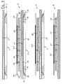
- first laminator 1 comprises a Laminating chamber 10, which is formed by a vacuum cabinet 11 is.
- the right in Figure 1 side wall of the vacuum cabinet 11 is as adjustable, e.g. movable or pivotable door 12 is formed.
- the door 12 in its open position in which they are the right side of the vacuum box 11 releases, and is therefore shown only in dashed lines.
- the laminating 2 Inside the laminating chamber 10 is a number of laminating plates 2 arranged one above the other. In the in FIG 1 shown operating state, the laminating 2 in each case a distance from each other.
- the laminating plates 2 are interconnected via connecting links 23 connected, here the form of vertical have running tie rods.
- the connecting links 23 each run through openings 24 in each case two adjacent laminating 2. by each an enlarged head at the two ends of the links is a limited vertical movement ever two adjacent laminating 2 relative to each other possible.
- lamination 2 engages a Lifting device 13, the e.g. through a spindle or a piston-cylinder arrangement is formed.
- a Lifting device 13 By means of this Lifting device 13, the laminating 2 in their visible in Figure 1, spaced apart position held, each with a laminating 2 the below the laminating plate over the links 23 stops.
- the laminating plates 2 include, except for the top and the lower laminating plate, each at the top a heating plate 20, including a plate frame 21 for the heating plate 20 and finally including a pressing device Third
- the pressing device 3 is in accordance with the laminator 1 Figure 1 each formed by a membrane 30, the on a membrane frame 32 is mounted sealingly.
- the area above each membrane 30 is in each case by a the plate frame 21, here the form of closed Have plates, sealed.
- channels or lines can the Space above the diaphragm 30 specifically evacuated or vented or be charged with a print medium.
- the upper laminating plate 2 comprises only the plate frame 21 and below the pressing device 3; at the bottom in the laminator 1 is located on a plate frame 21, a heating plate 20.
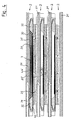
- the vacuum cabinet 11 closed by closing the door 12.
- the laminating chamber 10 is hermetically sealed and can then by a vacuum pump, not shown here be evacuated in the required manner.
- the lifting device 13 are the individual laminating 2 moved down and in their together driven position, as shown in the figure 2, through the Lifting device 13 fixed.
- the Membranes 30 practice the Membranes 30 as pressing device 3 a flat pressing force on the respective below the membrane 30 lying Component 4 with its laminate layers 4 'from. simultaneously is the component 4 with its laminate layers 4 'of below through the respective underlying heating plate 20 heated, thereby using heat and pressure the lamination process takes place.
- the lifting device 13 actuated and the laminating chamber 10 ventilated. As a result, the laminator 1 returns to the state the figure 1 shows. After opening the door 12, the now finished laminated components 4 of the individual heating plates 20 of the laminating 2 are removed. After that can be a new lamination process with simultaneous lamination start from several components 4.
- FIGS 1 and 2 clearly illustrate that the Laminator 1 for simultaneous lamination of several Components 4, here in the example a total of twelve components 4, no larger footprint than with a laminator only a heating plate 20 and an associated pressing device Third
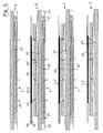
- Figure 3 shows an enlarged view of the upper, the bottom and two of the intermediate laminating plates 2 of the laminator according to Figure 1 in an enlarged Presentation.
- the upper laminating plate 2 according to FIG. 3 consists only of the plate frame 21 and arranged from underneath Pressing device 3.
- the lower laminating 2 includes a plate frame 21 and about a heating plate 20 with an associated heater 20 ', for example electrically or in an alternative embodiment by means a hot liquid is operable.
- the two intermediate laminating plates shown 2 comprise each as a supporting part a plate frame 21, on the top of each a hot plate 20 with the associated heater 20 'is arranged is. At the bottom of each plate frame 21 is one each the pressing devices 3 are arranged.
- These cute elements 25 are by spring force in Ausschubraum biased upward from the upper surface of the heating plate 20.
- Lower and upper side Here is also the component 4 with its laminate layers 4 'of a lower and an upper cover 40 covered.
- the lifting elements 25 is the from the cover sheets 40 on both sides covered component 4 with its laminate layers 4 'at a distance from the hot Hot plate 20 held.
- Lowering the components 4 with their laminate layers 4 'and their cover sheets 40 the surface of the hot heating plate 20 takes place first by moving together the laminating 2.
- the pressing devices 3 each include in addition to the Membrane 30 a membrane frame 32, on which the membrane 30th by means of an edge profile 33 without tools or by means Tool insert is clamped sealing.
- the membrane frame 32 with the clamped membrane 30 is in a Sliding guide 22 and held parallel to the surface plane the membrane 30 and perpendicular to the plane of the drawing displaced. In this way, the membrane frame 32 with the membrane 30 simply from the lamination 2 by pulling out be disconnected for a quick exchange allow the membrane 30 when needed.
- an air channel 34 Above the membrane 30 is an air channel 34, with an area above the membrane 30 and below of the membrane 30 sealed, plate-shaped Plate frame 21 opens. Through the air duct 34 the area above the membrane 30 can be evacuated, as shown in Figure 3. If necessary can through the air duct 34 air or other pressure medium be fed to deflect the membrane downwards and to apply a downward force.
- FIG. 4 of the drawing shows the four laminating plates 2 from Figure 3 now in their driven together state.
- This state is in each case a laminating 2 the downwardly adjacent laminating 2 on.
- a Stop for this edition forms in each case the membrane frame 32, which is on top of the edge of the Heating plate 20 rests.
- FIG. 4 further shows, here is the area above the upper diaphragm 30 vented, resulting here forms a now filled with air diaphragm chamber 31.
- the environment of the laminating plates 2 is as indicated by Figure 2 illustrates, evacuated for the lamination, so that for filling the diaphragm chamber 31 with air admitting of air under atmospheric pressure is sufficient.
- the membrane 30 in the in Figure 4 in the upper laminating 2 shown pressed down shape and exerts a flat pressing force on the component 4 with its laminate layers 4 'and its cover sheets 40 off.
- Figure 5 of the drawing shows in the same representation like Figure 3 shows a modified version of the laminator.
- This change relates to the type of pressing device 3.
- the pressing device 3 is the third each by one with a compressible, self-resetting Material 30 'deposited membrane formed, the expediently consists of an elastic-flexible material.
- Figure 5 shows at each laminating 2 of this downwardly projecting hold-down pins 26, the are arranged to match the lifting elements 25.
- These Hold-down pins 26 serve, when moving together the Laminierplatten 2 each lying below them lifting elements 25 in the associated heating plate 20 to move.
- the laminating plates 2 correspond to FIG 5 the laminating plates 2 according to FIG. 3.
- FIG. 6 shows the laminating plates 2 from FIG. 5 in FIG their together driven condition.
- one laminating plate 2 lies close to its adjacent one Laminierplatte 2 on.
- the Holding frame 32 forms the Holding frame 32 'a defined stop for this together driven position of laminating plates 2.
- each deposited with the material 30 ' Membranes a surface pressure on each Component 4 with its laminate layers 4 'and its cover sheets 40 off.
- the lifting elements 25 are in this state pushed back into the heating plates 20 so that now the component 4 with its laminate layers 40 over its entire surface rests on the respectively associated heating plate 20.
- the pressing devices are 3 to a sufficient extent elastic-flexible, so that, as illustrated in FIG. 6, adapt to the shape of the component 4 and its thickness.
- the strength and thickness of the elastic-flexible Material 30 'of the pressing devices 3 can the on the component 4 and its laminate layers 4 ' applied Andschreibkraft be determined.
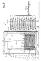
- FIG. 7 shows a further embodiment of the laminator 1, which is now equipped with a conveyor 5, the automatic loading of the laminator 1 with to be laminated Components 4 and unloading of laminated components 4 allowed from the laminator 1.
- the laminating chamber 10 is shown, which also formed here by a vacuum cabinet 11 is.
- the right in Figure 7 side wall of the vacuum cabinet 11 is designed as a sliding door 12, the is here in its open position in which they moved backwards.
- the conveyor 5 comprises two component storage 53, 54, which optionally in front of the open side of Laminating 10 can be positioned. Every component memory 53, 54 takes one of the number of laminating plates 2 in the laminator 1 corresponding number of to be laminated Components 4 or finished laminated components 4 in a the distance of the laminating 2 in the apart driven condition corresponding height distance from each other. This can be done purely by pure horizontal transport movement all components to be laminated simultaneously transported into the laminator 1 or at the same time after the lamination process from the laminator 1 be promoted.
- the laminating chamber 10 associated Conveyor 5 a conveyor belt 50.
- the conveyor belt 50 is from a supply roll 50 ', the outside of the vacuum cabinet 11 is disposed, unwound.
- the conveyor belt 50 arrives at the open side wall in the interior of the laminating 10th and passes through this meandering. It covers over the conveyor belt 50 each laminating plate 2 parallel to the latter Top and parallel to the bottom.
- Within the Laminating 10 are corresponding pulleys 51 arranged on the left and right of the laminating 2.
- the conveyor belt 5 leaves at the upper end of the Laminating 10 this through the open side and is via further deflection rollers 51 to a collecting roller 50 '' for the conveyor belt 50, where the conveyor belt 5 after its use is wound up.
- the component stores 53, 54 have a plurality of endless conveyor belts, each with its top the bearing surface for a component 4 to be laminated, inclusive its laminate layers 4 'or for a finished laminated Form component 4.
- the component memory 53, 54 placed so that its individual conveyor belts in direct comparison stand to the individual laminating 2. In this Position can then be activated by activating the conveyor 5 and the individual conveyor belts in the component memory 53, 54, the transfer of the components 4 either from the component memory 53, 54 on the laminating 2 or vice versa from the laminating 2 in the component memory 53, 54 take place.
- the conveyor belt 50 the here the laminating chamber 10 meandering passes through, can simultaneously as a cover film for the bottom and top of the to be laminated Components 4 are used during the lamination process, because the conveyor belt 50 on one side between the Heating plate 20 and the component 4 and on the other side between the pressing device 3 and the component 4 lies.
- a band tensioning unit 51 ' provided here on the top left and bottom left of the vacuum cabinet 11 and the left in Figure 7 vertical guides 14 acts according to the above left in Figure 7 drawn double arrow 14 'in the sense of Relaxing or tensioning of the band 5 to move.
- FIG. 8 shows the laminator 1 from FIG. 7 in its state during a lamination process.
- These are the Moving laminating plates 2 in their collapsed position, for which the lifting device 13 is used.
- the the individual lamination plates 2 associated pulleys 51st and the conveyor belt 50 are doing together with the laminating 2 drove down.
- the Belt tensioning unit 51 'in the sense of a relaxation of the conveyor belt 50 this gives it so much freedom that it does Applying the pressing force on the components 4 with their laminate layers 4 'not obstructed during the lamination process.
- the component memory 53, 54 at a greater distance from the vacuum cabinet 11 brought so that now the door 12, the vacuum cabinet 11 tightly closes.
- Means is the laminating chamber 10 for the lamination process evacuated.
- the conveyor belt 50 of the conveyor 5 stands during the lamination process still. This is the condition in this condition Conveyor 50 down and up between the door and the rest Vacuum cupboard 11. Since with closed door 12 no Movement of the conveyor belt 5 is required, the Conveyor 50 easy between door 12 and the rest of the vacuum cabinet 11 are clamped sealing.
- the individual Laminierplatten 2 by activation of the lifting device 13 brought back to their divergent position, as it shows the figure 7.
- the door 12 can be opened. After that can the finished laminated components 4 to the component memory 53, 54 or to one of several component stores Pass 53, 54 and then over the discharge line 54 'are discharged. After reloading the individual Laminating plates by transfer of to be laminated further components 4 from the component memory 53, 54 can to run a new lamination process.
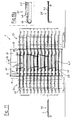
- FIG. 9 of the drawing shows the laminator 1 from FIG. 7 and Figure 8 in plan view.
- the vacuum cabinet 10 visible, which limits the laminating 10.
- the upper wall is omitted here.
- FIG. 9 shows particularly clearly, here are two Component memory 53, 54 used, the component memory 53 a storage for loading the laminating chamber 10 and the component memory 54 an unloading memory for unloading the laminating chamber 10.
- FIG. 10 shows a modification of the laminator 1 according to FIGS FIGS. 7 to 9.
- the modification here is that in the case of the laminator 1 according to FIG. 10, an endless conveyor belt 50 is used.
- the guide of the conveyor belt 50 in a meandering course through the laminating 10 is opposite to the embodiment of the laminator 1 according to the figures 7 to 9 unchanged.
- a cleaning station 55 is provided with the end of the endless conveyor belt 50 after its exit the vacuum cabinet 11 and before its re-entry into the vacuum cabinet 11 can be cleaned.
- adhesions from the conveyor belt 50 are removed, the quality of the surfaces could affect the laminated components 4.
- These adhesions may e.g. Be plastic drops that in the lamination process by liquefaction of thermoplastic Plastics that make up the laminating films exist, can arise.
- the cleaning station comprises 55 three consecutively arranged cleaning brushes 56, by drive means, not shown are rotary drivable, as well as two stationary Cleaning scraper 57, all on the zu cleaning surface of the conveyor belt 50 act.
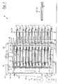
- FIGS 11, 11a and 12 show an embodiment of the laminator 1, in which the conveyor 5 by conveyor chains 58 is formed.
- each laminating 2, which are also vertically movable one above the other inside the Laminating chamber 10 are arranged, a chain conveyor with associated with two parallel conveyor chains 58.
- FIG. 11 Another change of the laminator 1 according to the figures 11, 11 a and 12 is that the vacuum cabinet 11 here on two opposite sides each with a sliding doors 12 is formed. This is a promotion of the components to be laminated 4 in the laminating 10 and a promotion of the finished laminated Components 4 from the laminating chamber 10 with a uniform, same conveying direction possible, as shown in FIG 11 is indicated by arrows.
- a first component memory 53 arranged as a storage.
- Component memory 53 can be laminated components 4 be stored in an altitude, the altitude of the Laminierplatten 2 in their moved apart position corresponds, as Figure 11 shows.
- With the door open 12 on the right side of the vacuum box 11 can by means provided in the component memory 53 chain conveyor all to be laminated components 4 simultaneously be transferred to the laminating 2.
- a second component memory 54 which serves as a discharge storage here. Also this component memory 54 is equipped with conveyor chains 58.
- conveyor chains 58 When open left door 12 of the vacuum box 11 can by activation of the conveyor 5 with the various Conveyor chains 58 all finished laminated components. 4 at the same height of the laminating 2 at the same pass individual floors of the left component memory 54 become.
- the cover sheets 40 are at their respective front, i. in Figure 11a left end with retaining means, e.g. rods provided, which engage with the conveyor chain 58 of the feed line 53 are brought, which then the cover sheets 40 at the same time as transport foils for the component. 4 serve with its laminate layers 4 '.
- retaining means e.g. rods provided
- cover foils 40 additionally serve as transport foils, each in engagement with the conveyor chains 58 of the Conveyor 5 in the laminating chamber 10, in the component memory 53 and in the component memory 54 can be brought.
- FIG. 12 shows the laminator 1 according to FIG. 11 in plan view, the arrangement of the individual parts is particularly becomes clear.
- the lower part of Figure 12 is in the Center of the vacuum cabinet 11 with the enclosed by this Laminating chamber 10 visible, with an upper wall of the Vacuum box 11 is omitted here to take a look to allow the interior of the laminating 10.
- the both doors 12 of the vacuum box 11 are behind, i.e. moved upward according to Figure 12, so that the left and right side of the vacuum box 11 here are open.
- the first component memory 53 for loading the individual laminating 2 serves.
- the feed path 53 ' which in turn for supplying the to be laminated Components 4 and their laminate layers 4 'and the Cover foils 40 and their distribution to the individual Floors of the component memory 53 is used.
- This component memory 54 takes the finished laminated after a lamination process Components 4 of the individual lamination 2 on. About the leftmost in Figure 12 visible discharge line 54 'are the finished laminated components gradually removed from the component memory 54 and conveyed away.
- the conveying device is 5 for the transport of the to be laminated and the Laminated components 4 formed by conveyor chains 58.
- FIG. 12 shows that the individual conveyor chains 58 each parallel to each other and extending in the conveying direction at the feed section 53 ', at the first component store 53, on the individual laminating plates 2, on the second Component memory 54 and provided on the discharge line 54 ' are.
- FIGs 13, 13a and 14 show in the same representation like Figures 11, 11a and 12 another Embodiment of the laminator 1, wherein the conveyor 5 formed by slide and gripper assemblies 52, 52 ' are. There are slide gripper assemblies 52, 52 'again here at the feed section 53', at the first Component memory 53, on the individual laminating plates 2, on the second component memory 54 and on the discharge line 54 'provided.
- FIG. 13a shows an enlarged view of the end region a slider gripper assembly 52, 52 '.
- the one in the end the slider 52 provided gripper 52 ' is in the Able, the two cover sheets 40, below and above of the component 4 with its laminate layers 4 ', to seize.
- the slider By moving the slider are then in the desired direction, the components. 4 with their laminate layers 4 'with the help of here as well conveyed as transport foils cover foils 40 promoted.
Landscapes
- Engineering & Computer Science (AREA)
- Mechanical Engineering (AREA)
- Physics & Mathematics (AREA)
- Fluid Mechanics (AREA)
- Lining Or Joining Of Plastics Or The Like (AREA)
- Photovoltaic Devices (AREA)
Abstract
Description
- Figur 1
- einen ersten Laminator in Seiteneinsicht, teils in Vertikalschnitt, in einem ersten Betriebszustand,
- Figur 2
- den Laminator aus Figur 1 in gleicher Darstellung in einem zweiten Betriebszustand,
- Figur 3
- einen vergrößerten Ausschnitt aus dem Inneren des Laminators gemäß Figur 1 im Vertikalschnitt,
- Figur 4
- einen vergrößerten Ausschnitt aus dem Inneren des Laminators gemäß Figur 2, ebenfalls im Vertikalschnitt,
- Figur 5
- einen vergrößerten Ausschnitt aus einem zweiten Laminator in einem ersten Betriebszustand im Vertikalschnitt,
- Figur 6
- den Ausschnitt gemäß Figur 5, nun in einem zweiten Betriebszustand in gleicher Darstellung,
- Figur 7
- eine dritte Ausführung des Laminators mit einer Fördereinrichtung, in einem ersten Betriebszustand, in Seitenansicht, teils im Vertikalschnitt,
- Figur 8
- den Laminator mit Fördereinrichtung aus Figur 7 in gleicher Darstellung in einem zweiten Betriebszustand,
- Figur 9
- den Laminator mit Fördereinrichtung gemäß Figur 7 und Figur 8 in Draufsicht,
- Figur 10
- den Laminator gemäß Figur 7 in gleicher Darstellung und in gleichem Betriebszustand, nun mit einer Reinigungsstation für die Fördereinrichtung,
- Figur 11
- den Laminator in einer weiteren Ausführung, ebenfalls mit einer Fördereinrichtung, teils in Seitenansicht, teils im Vertikalschnitt,
- Figur 11a
- ein vergrößertes Detail aus der Fördereinrichtung gemäß Figur 11 in Seitenansicht,
- Figur 12
- den Laminator aus Figur 11 in Draufsicht,
- Figur 13
- eine weitere Ausführung des Laminators mit einer geänderten Fördereinrichtung, teils in Seitenansicht, teils im Vertikalschnitt,
- Figur 13a
- ein vergrößertes Detail der Fördereinrichtung gemäß Figur 13 in Seitenansicht und
- Figur 14
- den Laminator aus Figur 13 in Draufsicht.
Claims (32)
- Laminator (1) zum Herstellen von Schichtkörpern, bestehend aus mindestens einer Laminierkammer (10) mit mehreren darin etagenartig angeordneten, beheizbaren Laminierplatten (2), wobei auf jeder Laminierplatte (2) jeweils eine oder mehrere Laminatschichten (4') mit einem Bauteil (4) verschweißbar sind und wobei der Laminator (1) Mittel zum Ausüben einer Andrückkraft auf die Bauteile (4) und die Laminatschichten (4') während des Laminiervorgangs aufweist,
dadurch gekennzeichnet, daß pro Laminierplatte (2) je eine Andrückeinrichtung (3) vorgesehen ist, die jeweils durch eine randseitig dicht eingespannte Membran (30) gebildet ist, die an ihrer von einem benachbarten Bauteil (4) und den zugehörigen Laminatschichten (4') abgewandten Seite eine evakuierbare und belüftbare oder mit einem Druckmedium beschickbare oder von einem komprimierbaren und selbstrückstellbaren Material gefüllte Membrankammer (31) begrenzt. - Laminator nach Anspruch 1, dadurch gekennzeichnet, daß die Laminierkammer (10) durch wenigstens einen Deckel oder eine Tür (12) geöffnet und geschlossen werden kann und im geschlossenen Zustand luftdicht und zur Ausführung eines Laminiervorganges unter Vakuum evakuierbar ist.
- Laminator nach Anspruch 2, dadurch gekennzeichnet, daß alle Laminierplatten (2) und Andrückeinrichtungen (3) in einer einzigen gemeinsamen Laminierkammer (10) angeordnet sind.
- Laminator nach Anspruch 3, dadurch gekennzeichnet, daß die gemeinsame Laminierkammer (10) durch einen Vakuumschrank (11) gebildet ist, in dem die Laminierplatten (2) in horizontaler Ausrichtung angeordnet sind und an dem mindestens eine Seitenwand als verstellbare Tür (12) ausgebildet ist.
- Laminator nach einem der vorhergehenden Ansprüche, dadurch gekennzeichnet, daß die Laminierplatten (2) vertikal bewegbar geführt sind und zwischen einer auseinander gefahrenen Stellung für das Zuführen der Bauteile (4) und der Laminatschichten (4') und für das Abführen der laminierten Bauteile (4) einerseits und einer zusammen gefahrenen Stellung für den Laminiervorgang andererseits verfahrbar sind.
- Laminator nach Anspruch 5, dadurch gekennzeichnet, daß jede Laminierplatte (2) je einen eigenen Plattenrahmen (21) für ihre Halterung aufweist, der jeweils seinerseits in einem in der Laminierkammer (10) angeordneten Führungsrahmen (14), der die vertikale Bewegbarkeit der Laminierplatten (2) ermöglicht, geführt und gehaltert ist.
- Laminator nach einem der vorhergehenden Ansprüche, dadurch gekennzeichnet, daß jede der Laminierplatten (2) mindestens eine Heizplatte (20) aufweist oder umfaßt.
- Laminator nach Anspruch 5 oder 6 und nach Anspruch 7, dadurch gekennzeichnet, daß die Heizplatte (20) jeweils an der Oberseite und die Andrückeinrichtung (3) jeweils an der Unterseite der Laminierplatte (2) angeordnet ist und daß im zusammen gefahrenen Zustand der Laminierplatten (2) mittels der Andrückeinrichtung (3) jeweils in Richtung zu der Heizplatte (20) der darunterliegenden Laminierplatte (2) die Andrückkraft ausübbar ist.
- Laminator nach einem der vorhergehenden Ansprüche, dadurch gekennzeichnet, daß jede Membran (30) auf/in je einen eigenen, von der zugehörigen Laminierplatte (2) trennbaren Membranrahmen (32) dichtend aufgespannt oder aufgeschraubt oder eingespannt ist.
- Laminator nach Anspruch 9, dadurch gekennzeichnet, daß jeder Membranrahmen (32) in je einer parallel zur Flächenebene der Membran (30) in der zugehörigen Laminierplatte (2) verlaufenden Schiebeführung (22) werkzeuglos einschiebbar und herausziehbar gehaltert ist.
- Laminator nach Anspruch 9 oder 10, dadurch gekennzeichnet, daß jede Membran (30) an ihrem Umfang mit einem umlaufenden Randprofil (33) versehen ist, wobei das Randprofil (33) im Querschnitt hakenförmig ist und im auf den Membranrahmen (32) aufgespannten Zustand der Membran (30) den Membranrahmen (32) an dessen Außenumfang hintergreift und wobei das Randprofil (33) werkzeuglos oder mittels Werkzeugeinsatzes jeweils in und außer Eingriff mit dem Membranrahmen (32) der zugehörigen Laminierplatte (2) bringbar ist.
- Laminator nach einem der vorhergehenden Ansprüche, dadurch gekennzeichnet, daß die Membran (30) aus einem elastisch-flexiblen Material gebildet ist.
- Laminator nach einem der vorhergehenden Ansprüche, dadurch gekennzeichnet, daß jeder Laminierplatte (2) ein oder mehrere Anschläge zugeordnet sind, die im zusammen gefahrenen Zustand der Laminierplatten (2) für eine definierte Lage der Laminierplatten (2) relativ zueinander sorgen.
- Laminator nach Anspruch 13, dadurch gekennzeichnet, daß der Anschlag/die Anschläge durch den Membranrahmen (32) oder den Halterahmen (32') der Laminierplatte (2) oder eine an dem Rahmen (32, 32') vorgesehene Rahmenbefestigung gebildet ist/sind.
- Laminator nach einem der Ansprüche 5 bis 14, dadurch gekennzeichnet, daß mindestens eine an der oberen oder an der unteren Laminierplatte (2) angreifende, auf- und abwärts verfahrbare Hubeinrichtung (13) vorgesehen ist und daß die Laminierplatten (2) untereinander über Verbindungsglieder (23) so verbunden sind, daß bei Bewegung der Hubeinrichtung (13) in einer ersten Bewegungsrichtung die Laminierplatten (2) aus ihrer zusammen gefahrenen Stellung heraus nach und nach fortschreitend in deren auseinander gefahrene Stellung überführbar sind und daß bei Bewegung der Hubeinrichtung (13) in einer zweiten Bewegungsrichtung die Laminierplatten (2) aus ihrer auseinander gefahrenen Stellung heraus nach und nach fortschreitend in deren zusammen gefahrene Stellung überführbar sind.
- Laminator nach Anspruch 15, dadurch gekennzeichnet, daß die Hubeinrichtung (13) durch mindestens eine Kolben-Zylinder-Einheit oder durch mindestens eine motorisch verstellbare Spindel gebildet ist.
- Laminator nach Anspruch 15 oder 16, dadurch gekennzeichnet, daß die Verbindungsglieder (23) je Laminierplatte (2) durch mehrere Zugstangen gebildet sind, die jeweils an ihrem einen Ende mit einer Laminierplatte (2) fest verbunden sind, die jeweils durch eine Durchbrechung (24) in der nach unten oder oben folgenden Laminierplatte (2) verlaufen und die an ihrem anderen Ende einen vergrößerten, nicht durch die Durchbrechung (24) passenden Kopf oder Anschlag aufweisen.
- Laminator nach einem der Ansprüche 1 bis 4 und nach Anspruch 7, dadurch gekennzeichnet, daß alle Laminierplatten (2) im Abstand voneinander höhenfest angeordnet sind und daß relativ dazu die Andrückeinrichtungen (3) und/oder die Heizplatten (20) höhenverstellbar sind.
- Laminator nach Anspruch 18, dadurch gekennzeichnet, daß jeweils eine Laminierplatte (2) mit der jeweils zugehörigen Heizplatte (20) und Andrückeinrichtung (3) oder jeweils eine Gruppe aus mehreren Laminierplatten (2) mit den zugehörigen Heizplatten (20) und Andrückeinrichtungen (3) in je einer eigenen, für sich evakuierbaren Laminierkammer (10) angeordnet ist.
- Laminator nach einem der Ansprüche 7 bis 19, dadurch gekennzeichnet, daß jede Heizplatte (20) mit Hubelementen (25), vorzugsweise in Form von in die Heizplatte (20) eingelassenen Hubstiften oder Hubleisten, ausgestattet ist, die wahlweise ein Abheben eines zu laminierenden Bauteils (4) und seiner Laminatschichten (4') oder eines laminierten Bauteils (4) von der Heizplatte (20) oder ein Absenken des zu laminierenden Bauteils (4) und seiner Laminatschichten (4') auf die Heizplatte (20) gestatten.
- Laminator nach einem der vorhergehenden Ansprüche, dadurch gekennzeichnet, daß er eine die zu laminierenden Bauteile (4) und die Laminatschichten (4') zuführende und/oder die laminierten Bauteile (4) nach dem Laminiervorgang abführende Fördereinrichtung (5) umfaßt.
- Laminator nach Anspruch 21, dadurch gekennzeichnet, daß die Fördereinrichtung (5) pro Laminierplatte (2) je ein eigenes, eine das zu laminierende Bauteil (4) und die Laminatschichten (4') tragende Oberfläche der Laminierplatte (2) überstreichendes, endloses oder endliches Förderband (50) umfaßt.
- Laminator nach Anspruch 22, dadurch gekennzeichnet, daß das Förderband (50) außer der das zu laminierende Bauteil (4) und die Laminatschichten (4') tragenden Oberfläche der Laminierplatte (2) auch die jeweils darunterliegende oder darüberliegende Andrückeinrichtung (3) überstreicht.
- Laminator nach Anspruch 21, dadurch gekennzeichnet, daß die Fördereinrichtung (5) ein einziges, den Laminator (1) mäanderförmig durchlaufendes, alle Laminierplatten (2) überstreichendes, endloses oder endliches Förderband (50) umfaßt.
- Laminator nach Anspruch 24, dadurch gekennzeichnet, daß das Förderband (50) außer allen das zu laminierende Bauteil (4) und die Laminatschichten (4') tragenden Oberflächen der Laminierplatten (2) auch alle Andrückeinrichtungen (3) überstreicht.
- Laminator nach Anspruch 21, dadurch gekennzeichnet, daß die Fördereinrichtung (5) mindestens eine in Zu- und Abförderrichtung bewegbare Greifer- und Schieberanordnung (52) umfaßt.
- Laminator nach einem der Ansprüche 21 bis 26, dadurch gekennzeichnet, daß die Fördereinrichtung (5) mindestens einen Bauteile-Vorratsspeicher (53) umfaßt, in dem eine der Zahl der Laminierplatten (2) entsprechende Zahl von zu laminierenden Bauteilen (4) mit den zugehörigen Laminatschichten (4') in einer der jeweiligen Höhenlage der einzelnen Laminierplatten (2) in deren auseinander gefahrener Stellung entsprechenden Höhenlage unterbringbar ist und aus dem die zu laminierenden Bauteile (4) mit den zugehörigen Laminatschichten (4') selbsttätig in eine Laminierposition auf den Laminierplatten (2) überführbar sind.
- Laminator nach einem der Ansprüche 21 bis 27, dadurch gekennzeichnet, daß die Fördereinrichtung (5) wenigstens einen Bauteile-Entladespeicher (54) umfaßt, in den eine der Zahl der Laminierplatten (2) entsprechende Zahl von laminierten Bauteilen (4) in einer der jeweiligen Höhenlage der einzelnen Laminierplatten (2) in deren auseinander gefahrener Stellung entsprechenden Höhenlage unterbringbar ist, wobei die laminierten Bauteile (4) nach dem Laminiervorgang selbsttätig von den Laminierplatten (2) in den Bauteile-Entladespeicher (54) zur Abführung überführbar sind.
- Laminator nach einem der vorhergehenden Ansprüche, dadurch gekennzeichnet, daß er je eine Zuführ- und Abführeinrichtung (41, 42) für mindestens eine das zu laminierende Bauteil (4) und die Laminatschichten (4') oberseitig und/oder unterseitig abdeckende, nach dem Laminiervorgang vom laminierten Bauteil (4) trennbare Abdeckfolie (40) umfaßt.
- Laminator nach einem der Ansprüche 22 bis 25 oder nach Anspruch 29, dadurch gekennzeichnet, daß jedes Förderband (50) ein wieder verwendbares Band ist und/oder daß jede Abdeckfolie (40) eine wieder verwendbare Folie ist, wobei für jedes Förderband (50) und/oder für jede Abdeckfolie (40) eine Reinigungsstation (55) im oder am Laminator (1) oder als separate Station vorgesehen ist.
- Laminator nach Anspruch 30, dadurch gekennzeichnet, daß die Reinigungsstation (55) mindestens eine drehantreibbare Reinigungsbürste (56) und mindestens einen Reinigungsschaber (57) umfaßt, die jeweils in Wirkeingriff mit der Seite/den Seiten des Förderbandes (50) und/oder der Abdeckfolie (40) bringbar sind, die beim Laminiervorgang mit den Laminatschichten (4') in Kontakt tritt/treten.
- Laminator nach einem der Ansprüche 22 bis 25 oder nach Anspruch 29, dadurch gekennzeichnet, daß jedes Förderband (50) ein nur einmal verwendbares Band ist und/oder daß jede Abdeckfolie (40) eine nur einmal verwendbare Folie ist, wobei das Band (50) und/oder die Folie (40) nach ihrer Verwendung entsorgbar und durch ein frisches Band (50) und/oder durch eine frische Folie (40) ersetzbar ist.
Applications Claiming Priority (2)
| Application Number | Priority Date | Filing Date | Title |
|---|---|---|---|
| DE102004027545 | 2004-06-04 | ||
| DE200410027545 DE102004027545A1 (de) | 2004-06-04 | 2004-06-04 | Vorrichtung für das heiße Laminieren und anschließende Abkühlen von Bauteilen |
Publications (2)
| Publication Number | Publication Date |
|---|---|
| EP1609597A2 true EP1609597A2 (de) | 2005-12-28 |
| EP1609597A3 EP1609597A3 (de) | 2006-03-22 |
Family
ID=34937202
Family Applications (1)
| Application Number | Title | Priority Date | Filing Date |
|---|---|---|---|
| EP05011970A Withdrawn EP1609597A3 (de) | 2004-06-04 | 2005-06-03 | Laminator zum Herstellen von Schichtkörpern |
Country Status (2)
| Country | Link |
|---|---|
| EP (1) | EP1609597A3 (de) |
| DE (1) | DE102004027545A1 (de) |
Cited By (31)
| Publication number | Priority date | Publication date | Assignee | Title |
|---|---|---|---|---|
| JP2007054888A (ja) * | 2005-07-04 | 2007-03-08 | Meier Vakuumtechnik Gmbh | メンブランプレス |
| EP1997614A2 (de) | 2007-05-30 | 2008-12-03 | Robert Bürkle GmbH | Verfahren und Vorrichtung zum Laminieren von im Wesentlichen plattenförmigen Werkstücken unter Druck- und Wärmeeinwirkung |
| EP1997613A2 (de) | 2007-05-30 | 2008-12-03 | Robert Bürkle GmbH | Mehretagen-Laminierpresse |
| EP2065177A1 (de) * | 2007-11-30 | 2009-06-03 | komax Holding AG | Heizplatte mit Hubelementen |
| DE202009005897U1 (de) | 2009-04-22 | 2009-07-23 | Böhm Fertigungstechnik Suhl GmbH | Laminierpresse mit Transporteinrichtung |
| EP2127867A2 (de) | 2008-05-29 | 2009-12-02 | Robert Bürkle GmbH | Presse und Verfahren zum Laminieren von im Wesentlichen plattenförmigen Werkstücken |
| DE102009010351A1 (de) | 2009-02-25 | 2010-09-02 | Theodor Hymmen Holding Gmbh | Verfahren und Vorrichtung zum Verkleben von plattenförmigen und bahnförmigen Werkstoffen |
| DE102009042148A1 (de) | 2009-09-14 | 2011-03-24 | Schmid Technology Systems Gmbh | Etagenpresse und Verfahren zur Herstellung von plattenförmigen Werkstücken |
| CN102099192A (zh) * | 2008-05-15 | 2011-06-15 | 迈雅太阳能解决方案有限公司 | 用于层压构件的层压装置 |
| WO2011141433A1 (de) | 2010-05-11 | 2011-11-17 | Schmid Technology Systems Gmbh | Etagenpresse, etagenelement einer solchen etagenpresse und verfahren zur herstellung von plattenförmigen werkstücken mit einer solchen etagenpresse |
| WO2011141479A1 (de) * | 2010-05-11 | 2011-11-17 | Siempelkamp Maschinen- Und Anlagenbau Gmbh & Co. Kg | Vulkanisierpressenanlage |
| WO2012150030A3 (en) * | 2011-05-02 | 2013-03-28 | Centrotherm Photovoltaics Ag | Laminating device for laminating components |
| CN103273601A (zh) * | 2013-06-17 | 2013-09-04 | 贵州大自然科技有限公司 | 棕床垫热压成型方法及装置 |
| US9242434B2 (en) | 2009-10-09 | 2016-01-26 | Fotoverbundglas Marl Gmbh | Device and method for producing laminated safety glass |
| CN107053819A (zh) * | 2017-06-06 | 2017-08-18 | 济南月宫冷冻设备有限公司 | 层压机及层压机系统 |
| CN108453984A (zh) * | 2018-03-14 | 2018-08-28 | 常州市科诺电子设备有限公司 | 大吨位大幅面智能防火板材真空热压成套设备及制备方法 |
| EP3407393A1 (de) * | 2017-05-23 | 2018-11-28 | Meyer Burger (Switzerland) AG | Solarmodulfertigungsstrasse |
| DE102017005609A1 (de) * | 2017-06-13 | 2018-12-13 | Mühlbauer Gmbh & Co. Kg | Mehrlagige Polymerverbundvorrichtung mit eingeschlossenen Bauteilen, Verfahren zur Herstellung von mehrlagigen Polymerverbundvorrichtungen mit eingeschlossenen Bauteilen und Vorrichtung zur Herstellung von mehrlagigen Polymerverbundvorrichtungen mit eingeschlossenen Bauteilen |
| CN109435416A (zh) * | 2018-12-17 | 2019-03-08 | 陆凤生 | 太阳能电池组件层压机 |
| CN109461793A (zh) * | 2018-12-17 | 2019-03-12 | 王立忠 | 用于太阳能电池组件的压合模块及制造太阳能电池组件的方法 |
| CN113840460A (zh) * | 2021-08-09 | 2021-12-24 | 深圳市鑫达辉软性电路科技有限公司 | 一种用于物联网的超高频柔性电路板压接的层压机 |
| EP3991971A1 (de) * | 2020-10-28 | 2022-05-04 | Qinhuangdao Visible Automation Equipment Co. Ltd. | Plattenpressenlaminator und druckaufbringungsverfahren |
| CN115101615A (zh) * | 2022-06-13 | 2022-09-23 | 秦皇岛凯伏澜新能源科技有限公司 | 封闭式光伏组件层压机、层压设备及层压方法 |
| CN115440850A (zh) * | 2022-09-22 | 2022-12-06 | 浙江晶科能源有限公司 | 光伏层压机、光伏组件的层压方法 |
| CN115674858A (zh) * | 2022-11-22 | 2023-02-03 | 浙江松发复合新材料有限公司 | 一种不锈钢覆铜板带轧制加工设备及方法 |
| CN115692529A (zh) * | 2023-01-04 | 2023-02-03 | 唐山海泰新能科技股份有限公司 | 一种分体渐进式层压机 |
| CN116968375A (zh) * | 2023-08-10 | 2023-10-31 | 河北科技师范学院 | 一种多层层压机加热片的快速拆装方法及热片式多层层压机及所用的加热片固定装置 |
| CN118358215A (zh) * | 2024-03-29 | 2024-07-19 | 泰州新源电工器材有限公司 | 一种绝缘纸板加工用热压机 |
| CN118664999A (zh) * | 2023-03-16 | 2024-09-20 | 浙江晶科能源有限公司 | 层压机和层压机的控制方法 |
| CN118952814A (zh) * | 2024-08-05 | 2024-11-15 | 山东福特尔新材料科技有限公司 | 一种环保无胶复合方块地毯真空层压固化装置 |
| EP4624156A1 (de) * | 2024-03-27 | 2025-10-01 | Prologium Technology Co., Ltd. | Laminiermaschine und laminierverfahren |
Families Citing this family (7)
| Publication number | Priority date | Publication date | Assignee | Title |
|---|---|---|---|---|
| DE102008044862A1 (de) * | 2008-08-28 | 2010-03-04 | Robert Bürkle GmbH | Verfahren und Laminierpresse zum Laminieren von Werkstücken |
| DE102010054993B4 (de) * | 2010-12-17 | 2016-02-25 | Wemhöner Surface GmbH & Co. KG | Laminiervorrichtung flächiger Werkstücke |
| DE102013100316A1 (de) * | 2013-01-11 | 2014-07-17 | L&S Technischer Handel Gmbh & Co. Kg | Vorrichtung und Verfahren zum Herstellen von Verbundglas |
| DE102014206751A1 (de) | 2014-04-08 | 2015-10-08 | Bayerische Motoren Werke Aktiengesellschaft | Verfahren und Fertigungssystem zum Kaschieren von Interieurkomponenten von Fahrzeugen |
| CN104494184A (zh) * | 2014-12-09 | 2015-04-08 | 浙江美诺华药物化学有限公司 | 一种用于化工原料中转槽板材的压板机 |
| CN111438974B (zh) * | 2020-04-01 | 2024-11-05 | 洛阳广盈机械设备有限公司 | 一种移出式自升降多层负压制板装置 |
| DE102022107462A1 (de) | 2022-03-29 | 2023-10-05 | Pva Industrial Vacuum Systems Gmbh | Hochtemperatur-Fügeofen |
Family Cites Families (14)
| Publication number | Priority date | Publication date | Assignee | Title |
|---|---|---|---|---|
| US4190484A (en) * | 1975-10-20 | 1980-02-26 | Rembert Duvelius | Press for producing shaped articles |
| DE3300622A1 (de) * | 1983-01-11 | 1984-07-12 | Licentia Patent-Verwaltungs-Gmbh, 6000 Frankfurt | Verfahren und vorrichtung zur herstellung eines aus mindestens zwei plattenfoermigen bauelementen bestehenden schichtkoerpers |
| JPS60151048A (ja) * | 1984-01-19 | 1985-08-08 | 日立化成工業株式会社 | 積層板の製造法 |
| FR2587273B1 (fr) * | 1985-09-19 | 1988-04-08 | Darragon Sa | Procede et presse-autoclave de stratification de circuits imprimes multicouches et/ou de plastification d'elements plats, et dispositif de transformation en presse-autoclave de ce type |
| DE3539989A1 (de) * | 1985-11-12 | 1987-05-14 | Lauffer Maschf | Presse zum laminieren von mehrlagenschaltungen |
| DE3725007A1 (de) * | 1987-07-29 | 1989-02-09 | Matsushita Electric Works Ltd | Viel-platten-presse zum herstellen von laminaten unter unterdruck |
| DE3844498A1 (de) * | 1988-12-30 | 1990-07-05 | Klaus Schneider | Vorrichtung zum verpressen von multilayerpaketen |
| DE9003398U1 (de) * | 1990-03-23 | 1991-07-25 | Robert Bosch Gmbh, 7000 Stuttgart | Mit einem Fluid betriebene Schließvorrichtung |
| DE4016565C2 (de) * | 1990-05-23 | 1995-04-20 | Fibron Gmbh | Aufheizeinrichtung für plattenförmige Zuschnitte thermoplastischer Kunststoffe |
| JPH09141743A (ja) * | 1995-11-24 | 1997-06-03 | N P C:Kk | ラミネート装置 |
| US5993582A (en) * | 1996-08-13 | 1999-11-30 | Canon Kabushiki Kaisha | Continuous vacuum lamination treatment system and vacuum lamination apparatus |
| ITMI981185A1 (it) * | 1998-05-28 | 1999-11-28 | Gen Electric | Piastra per idroformatura |
| SE520583C2 (sv) * | 2000-11-28 | 2003-07-29 | Flow Holdings Sagl | Pressanläggning av en tryckcellspress med en tråganordning delbar i en övre och nedre del samt förfarande för anläggningen och användning av anordningen |
| WO2003095186A1 (en) * | 2002-05-08 | 2003-11-20 | Flow Holdings Sagl | Fluid cell press with a gripping arrangement and method and use of the press |
-
2004
- 2004-06-04 DE DE200410027545 patent/DE102004027545A1/de not_active Withdrawn
-
2005
- 2005-06-03 EP EP05011970A patent/EP1609597A3/de not_active Withdrawn
Cited By (57)
| Publication number | Priority date | Publication date | Assignee | Title |
|---|---|---|---|---|
| JP2007054888A (ja) * | 2005-07-04 | 2007-03-08 | Meier Vakuumtechnik Gmbh | メンブランプレス |
| EP1741547A3 (de) * | 2005-07-04 | 2008-05-14 | Meier Vakuumtechnik GmbH | Membranpresse |
| DE102007025380A1 (de) | 2007-05-30 | 2008-12-04 | Robert Bürkle GmbH | Mehretagen-Laminierpresse |
| US7779884B2 (en) | 2007-05-30 | 2010-08-24 | Robert Burkle Gmbh | Multi-level laminating press |
| CN101314270B (zh) * | 2007-05-30 | 2012-07-04 | 罗伯特别克勒有限公司 | 用于在压力和热作用下层压板状工件的方法和装置 |
| JP2008296280A (ja) * | 2007-05-30 | 2008-12-11 | Robert Buerkle Gmbh | 多段積層プレス |
| DE102007034135A1 (de) | 2007-05-30 | 2009-01-29 | Robert Bürkle GmbH | Verfahren und Vorrichtung zum Laminieren von im Wesentlichen plattenförmigen Werkstücken unter Druck- und Wärmeeinwirkung |
| EP1997613A2 (de) | 2007-05-30 | 2008-12-03 | Robert Bürkle GmbH | Mehretagen-Laminierpresse |
| EP1997614A2 (de) | 2007-05-30 | 2008-12-03 | Robert Bürkle GmbH | Verfahren und Vorrichtung zum Laminieren von im Wesentlichen plattenförmigen Werkstücken unter Druck- und Wärmeeinwirkung |
| EP1997613A3 (de) * | 2007-05-30 | 2011-04-27 | Robert Bürkle GmbH | Mehretagen-Laminierpresse |
| EP1997614A3 (de) * | 2007-05-30 | 2010-09-22 | Robert Bürkle GmbH | Verfahren und Vorrichtung zum Laminieren von im Wesentlichen plattenförmigen Werkstücken unter Druck- und Wärmeeinwirkung |
| EP2065177A1 (de) * | 2007-11-30 | 2009-06-03 | komax Holding AG | Heizplatte mit Hubelementen |
| US8454357B2 (en) | 2007-11-30 | 2013-06-04 | Komax Holding Ag | Hotplate with lifting elements |
| CN102099192A (zh) * | 2008-05-15 | 2011-06-15 | 迈雅太阳能解决方案有限公司 | 用于层压构件的层压装置 |
| JP2009285731A (ja) * | 2008-05-29 | 2009-12-10 | Robert Buerkle Gmbh | 板状の加工物を積層するためのプレス機および方法 |
| DE102008025790A1 (de) | 2008-05-29 | 2009-12-03 | Robert Bürkle GmbH | Presse und Verfahren zum Laminieren von im Wesentlichen plattenförmigen Werkstücken |
| CN101590702A (zh) * | 2008-05-29 | 2009-12-02 | 罗伯特别克勒有限公司 | 用于层压基本为板形的工件的压力机和方法 |
| CN101590702B (zh) * | 2008-05-29 | 2013-02-20 | 罗伯特别克勒有限公司 | 用于层压基本为板形的工件的压力机和方法 |
| EP2127867A2 (de) | 2008-05-29 | 2009-12-02 | Robert Bürkle GmbH | Presse und Verfahren zum Laminieren von im Wesentlichen plattenförmigen Werkstücken |
| DE102009010351A1 (de) | 2009-02-25 | 2010-09-02 | Theodor Hymmen Holding Gmbh | Verfahren und Vorrichtung zum Verkleben von plattenförmigen und bahnförmigen Werkstoffen |
| DE202009005897U1 (de) | 2009-04-22 | 2009-07-23 | Böhm Fertigungstechnik Suhl GmbH | Laminierpresse mit Transporteinrichtung |
| DE102009042148A1 (de) | 2009-09-14 | 2011-03-24 | Schmid Technology Systems Gmbh | Etagenpresse und Verfahren zur Herstellung von plattenförmigen Werkstücken |
| DE102009042148B4 (de) | 2009-09-14 | 2019-10-10 | Schmid Technology Systems Gmbh | 14.09.2009Etagenpresse und Verfahren zur Herstellung von plattenförmigen Werkstücken |
| DE102009042148B8 (de) * | 2009-09-14 | 2019-12-12 | Schmid Technology Systems Gmbh | Etagenpresse und Verfahren zur Herstellung von plattenförmigen Werkstücken |
| US9242434B2 (en) | 2009-10-09 | 2016-01-26 | Fotoverbundglas Marl Gmbh | Device and method for producing laminated safety glass |
| WO2011141479A1 (de) * | 2010-05-11 | 2011-11-17 | Siempelkamp Maschinen- Und Anlagenbau Gmbh & Co. Kg | Vulkanisierpressenanlage |
| DE102010020930A1 (de) | 2010-05-11 | 2011-11-17 | Schmid Technology Systems Gmbh | Etagenpresse, Etagenelement einer solchen Etagenpresse und Verfahren zur Herstellung von plattenförmigen Werkstücken mit einer solchen Etagenpresse |
| WO2011141433A1 (de) | 2010-05-11 | 2011-11-17 | Schmid Technology Systems Gmbh | Etagenpresse, etagenelement einer solchen etagenpresse und verfahren zur herstellung von plattenförmigen werkstücken mit einer solchen etagenpresse |
| CN102933380A (zh) * | 2010-05-11 | 2013-02-13 | 西姆佩尔坎普机械设备制造有限责任公司和两合公司 | 硫化压力机系统 |
| CN102933380B (zh) * | 2010-05-11 | 2015-05-20 | 辛北尔康普机器及成套设备有限责任公司 | 硫化压力机系统 |
| WO2012150030A3 (en) * | 2011-05-02 | 2013-03-28 | Centrotherm Photovoltaics Ag | Laminating device for laminating components |
| CN103273601A (zh) * | 2013-06-17 | 2013-09-04 | 贵州大自然科技有限公司 | 棕床垫热压成型方法及装置 |
| CN103273601B (zh) * | 2013-06-17 | 2016-01-20 | 贵州大自然科技股份有限公司 | 棕床垫热压成型方法及装置 |
| EP3407393A1 (de) * | 2017-05-23 | 2018-11-28 | Meyer Burger (Switzerland) AG | Solarmodulfertigungsstrasse |
| WO2018215853A1 (en) * | 2017-05-23 | 2018-11-29 | Meyer Burger (Switzerland) Ag | Solar module production line |
| CN107053819A (zh) * | 2017-06-06 | 2017-08-18 | 济南月宫冷冻设备有限公司 | 层压机及层压机系统 |
| CN107053819B (zh) * | 2017-06-06 | 2022-12-16 | 济南月宫冷冻设备有限公司 | 层压机及层压机系统 |
| DE102017005609A1 (de) * | 2017-06-13 | 2018-12-13 | Mühlbauer Gmbh & Co. Kg | Mehrlagige Polymerverbundvorrichtung mit eingeschlossenen Bauteilen, Verfahren zur Herstellung von mehrlagigen Polymerverbundvorrichtungen mit eingeschlossenen Bauteilen und Vorrichtung zur Herstellung von mehrlagigen Polymerverbundvorrichtungen mit eingeschlossenen Bauteilen |
| US10740668B2 (en) | 2017-06-13 | 2020-08-11 | Muehlbauer GmbH & Co. KG | Multiply polymer composite device with enclosed components, method for producing multiply polymer composite devices with enclosed components and device for producing multiply polymer composite devices with enclosed components |
| DE102017005609B4 (de) | 2017-06-13 | 2022-04-21 | Mühlbauer Gmbh & Co. Kg | Mehrlagige Polymerverbundvorrichtung mit eingeschlossenen Bauteilen, Verfahren zur Herstellung von mehrlagigen Polymerverbundvorrichtungen mit eingeschlossenen Bauteilen und Vorrichtung zur Herstellung von mehrlagigen Polymerverbundvorrichtungen mit eingeschlossenen Bauteilen |
| CN108453984A (zh) * | 2018-03-14 | 2018-08-28 | 常州市科诺电子设备有限公司 | 大吨位大幅面智能防火板材真空热压成套设备及制备方法 |
| CN109461793A (zh) * | 2018-12-17 | 2019-03-12 | 王立忠 | 用于太阳能电池组件的压合模块及制造太阳能电池组件的方法 |
| CN109435416A (zh) * | 2018-12-17 | 2019-03-08 | 陆凤生 | 太阳能电池组件层压机 |
| EP3991971A1 (de) * | 2020-10-28 | 2022-05-04 | Qinhuangdao Visible Automation Equipment Co. Ltd. | Plattenpressenlaminator und druckaufbringungsverfahren |
| CN113840460A (zh) * | 2021-08-09 | 2021-12-24 | 深圳市鑫达辉软性电路科技有限公司 | 一种用于物联网的超高频柔性电路板压接的层压机 |
| CN115101615A (zh) * | 2022-06-13 | 2022-09-23 | 秦皇岛凯伏澜新能源科技有限公司 | 封闭式光伏组件层压机、层压设备及层压方法 |
| CN115101615B (zh) * | 2022-06-13 | 2024-05-24 | 苏州优敖智能科技有限公司 | 封闭式光伏组件层压机、层压设备及层压方法 |
| CN115440850A (zh) * | 2022-09-22 | 2022-12-06 | 浙江晶科能源有限公司 | 光伏层压机、光伏组件的层压方法 |
| CN115674858A (zh) * | 2022-11-22 | 2023-02-03 | 浙江松发复合新材料有限公司 | 一种不锈钢覆铜板带轧制加工设备及方法 |
| CN115692529A (zh) * | 2023-01-04 | 2023-02-03 | 唐山海泰新能科技股份有限公司 | 一种分体渐进式层压机 |
| CN115692529B (zh) * | 2023-01-04 | 2023-03-17 | 唐山海泰新能科技股份有限公司 | 一种分体渐进式层压机 |
| CN118664999A (zh) * | 2023-03-16 | 2024-09-20 | 浙江晶科能源有限公司 | 层压机和层压机的控制方法 |
| CN116968375A (zh) * | 2023-08-10 | 2023-10-31 | 河北科技师范学院 | 一种多层层压机加热片的快速拆装方法及热片式多层层压机及所用的加热片固定装置 |
| EP4624156A1 (de) * | 2024-03-27 | 2025-10-01 | Prologium Technology Co., Ltd. | Laminiermaschine und laminierverfahren |
| JP2025156050A (ja) * | 2024-03-27 | 2025-10-14 | 輝能科技股▲分▼有限公司 | 積層機械及び積層方法 |
| CN118358215A (zh) * | 2024-03-29 | 2024-07-19 | 泰州新源电工器材有限公司 | 一种绝缘纸板加工用热压机 |
| CN118952814A (zh) * | 2024-08-05 | 2024-11-15 | 山东福特尔新材料科技有限公司 | 一种环保无胶复合方块地毯真空层压固化装置 |
Also Published As
| Publication number | Publication date |
|---|---|
| DE102004027545A1 (de) | 2005-12-29 |
| DE102004027545A8 (de) | 2006-06-08 |
| EP1609597A3 (de) | 2006-03-22 |
Similar Documents
| Publication | Publication Date | Title |
|---|---|---|
| EP1609597A2 (de) | Laminator zum Herstellen von Schichtkörpern | |
| DE69019170T2 (de) | Vorgeschlitzte Injektionsstelle sowie konische Kanüle. | |
| EP1997614B1 (de) | Verfahren und Vorrichtung zum Laminieren von im Wesentlichen plattenförmigen Werkstücken unter Druck- und Wärmeeinwirkung | |
| EP2522581B1 (de) | Arbeitsstation für eine Verpackungsmaschine und Verfahren zum Werkzeugwechsel | |
| EP1997613B1 (de) | Mehretagen-Laminierpresse | |
| DE4113568C1 (de) | ||
| EP2141018A2 (de) | Verfahren und Vorrichtung zum Laminieren von im Wesentlichen plattenförmigen Werkstücken unter Druck- und Wärmeeinwirkung | |
| DE202008018124U1 (de) | Roboter mit Fügewerkzeug | |
| DD229791A5 (de) | Verfahren zum laminieren eines films unter druck und waerme und vorrichtung zur durchfuehrung des verfahrens | |
| DE112010001156T5 (de) | Laminiereinrichtung und Laminierverfahren für elne Solarbatterie | |
| DE102005060452A1 (de) | Handhabungsvorrichtung | |
| EP1907209A2 (de) | Maschine zur herstellung von plattenförmigen elementen aus verbundmaterial | |
| DE202013102624U1 (de) | Fertigungseinrichtung | |
| DE69020170T4 (de) | Apparat zum beschichten der oberfläche und der seitenkanten einer platte aus holz oder ähnlichem material mit einer wärmeverformbaren folie. | |
| DE3320078A1 (de) | Anordnung und verfahren zur herstellung von geschichteten einheiten | |
| DE102013101055A1 (de) | Verfahren und Vorrichtung zum Tiefziehen | |
| DE3420428A1 (de) | Verfahren zum laminieren eines films und vorrichtung zur durchfuehrung des verfahrens | |
| AT506120B1 (de) | Vorrichtung zum heizen oder kühlen plattenförmiger elemente | |
| DE69023011T2 (de) | Apparat zum beschichten einer oberfläche und der seitenkanten einer holzplatte oder ähnlichen materials mit einer wärmeverformbaren folie. | |
| DE3725007A1 (de) | Viel-platten-presse zum herstellen von laminaten unter unterdruck | |
| DE3223171A1 (de) | Vorrichtung zum verformen von platten aus thermoplastischem kunststoff | |
| DE2928231C2 (de) | ||
| AT506430A1 (de) | Distanzelement für plattenfírmige elemente | |
| DE4232963C1 (de) | Vorrichtung zum Aufbringen eines bedruckten Labels auf den Seitenwänden eines Kunststoffbehälters | |
| DE3514487A1 (de) | Verfahren und vorrichtung fuer die beschickung von stanzen, inline-maschinen o.dergl. mit aus wellpappebogen bestehenden paketen |
Legal Events
| Date | Code | Title | Description |
|---|---|---|---|
| PUAI | Public reference made under article 153(3) epc to a published international application that has entered the european phase |
Free format text: ORIGINAL CODE: 0009012 |
|
| AK | Designated contracting states |
Kind code of ref document: A2 Designated state(s): AT BE BG CH CY CZ DE DK EE ES FI FR GB GR HU IE IS IT LI LT LU MC NL PL PT RO SE SI SK TR |
|
| AX | Request for extension of the european patent |
Extension state: AL BA HR LV MK YU |
|
| PUAL | Search report despatched |
Free format text: ORIGINAL CODE: 0009013 |
|
| AK | Designated contracting states |
Kind code of ref document: A3 Designated state(s): AT BE BG CH CY CZ DE DK EE ES FI FR GB GR HU IE IS IT LI LT LU MC NL PL PT RO SE SI SK TR |
|
| AX | Request for extension of the european patent |
Extension state: AL BA HR LV MK YU |
|
| RIC1 | Information provided on ipc code assigned before grant |
Ipc: B30B 15/00 20060101ALI20060201BHEP Ipc: B30B 15/32 20060101ALI20060201BHEP Ipc: B30B 7/02 20060101ALI20060201BHEP Ipc: B30B 5/02 20060101ALI20060201BHEP Ipc: B32B 31/04 00000000AFI20050926BHEP |
|
| AKX | Designation fees paid | ||
| STAA | Information on the status of an ep patent application or granted ep patent |
Free format text: STATUS: THE APPLICATION IS DEEMED TO BE WITHDRAWN |
|
| 18D | Application deemed to be withdrawn |
Effective date: 20060923 |
|
| REG | Reference to a national code |
Ref country code: DE Ref legal event code: 8566 |