EP1609896B1 - Procédé pour la déposition de microcapsules dans un fil multifilament et produits correspondants - Google Patents
Procédé pour la déposition de microcapsules dans un fil multifilament et produits correspondants Download PDFInfo
- Publication number
- EP1609896B1 EP1609896B1 EP05253341A EP05253341A EP1609896B1 EP 1609896 B1 EP1609896 B1 EP 1609896B1 EP 05253341 A EP05253341 A EP 05253341A EP 05253341 A EP05253341 A EP 05253341A EP 1609896 B1 EP1609896 B1 EP 1609896B1
- Authority
- EP
- European Patent Office
- Prior art keywords
- yarn
- agents
- microcapsules
- filaments
- separating
- Prior art date
- Legal status (The legal status is an assumption and is not a legal conclusion. Google has not performed a legal analysis and makes no representation as to the accuracy of the status listed.)
- Expired - Lifetime
Links
Images


Classifications
-
- D—TEXTILES; PAPER
- D06—TREATMENT OF TEXTILES OR THE LIKE; LAUNDERING; FLEXIBLE MATERIALS NOT OTHERWISE PROVIDED FOR
- D06M—TREATMENT, NOT PROVIDED FOR ELSEWHERE IN CLASS D06, OF FIBRES, THREADS, YARNS, FABRICS, FEATHERS OR FIBROUS GOODS MADE FROM SUCH MATERIALS
- D06M23/00—Treatment of fibres, threads, yarns, fabrics or fibrous goods made from such materials, characterised by the process
- D06M23/12—Processes in which the treating agent is incorporated in microcapsules
-
- D—TEXTILES; PAPER
- D02—YARNS; MECHANICAL FINISHING OF YARNS OR ROPES; WARPING OR BEAMING
- D02G—CRIMPING OR CURLING FIBRES, FILAMENTS, THREADS, OR YARNS; YARNS OR THREADS
- D02G3/00—Yarns or threads, e.g. fancy yarns; Processes or apparatus for the production thereof, not otherwise provided for
- D02G3/22—Yarns or threads characterised by constructional features, e.g. blending, filament/fibre
- D02G3/40—Yarns in which fibres are united by adhesives; Impregnated yarns or threads
Definitions
- the present invention relates to a process for providing additives to yarn made of multifilament textiles.
- Micro-encapsulation has been used in the textile industry since the early 1990's. Many textile manufacturers are looking into the use of microcapsules to functionalize their products by giving textiles: a durable scent; a means for applying a cosmetic, such as a body lotion, or a pharmaceutical product.
- Microcapsules applied to textile materials impart characteristics which depend on the nature of the active substances present inside the microcapsules.
- the large number and variety of active substance that can be used is further proof of the usefulness of the micro-encapsulation technique in the fabrication of different textiles which have many applications.
- Microcapsules have been applied to the textile webs (woven, knitted and no woven fabrics), fibers, and monofilaments or multifilament yarns. The majority of described techniques for applying of microcapsules to the textiles is designated for the webs finishing.
- Impregnation is one method of web/fabric finishing.
- the web is placed in a treatment bath, such as a "pad” machine, which contains both charged microcapsules and a binder.
- Optionally products include: dispersing agents; pressure absorbing agents; softening agents and surfactants alone or in combination may also be added.
- the treated fabric must be dried and/or cured (soaking process); or squeezed and dried and/or cured (padding process).
- the binders anchor the microcapsules to the fabric.
- Suitable binders for microcapsule finishing include: polymeric melamine compounds; polymeric glyoxal compounds; polymeric silicone compounds; polyalkylene glycols; poly(meth)acrylates; polymeric fluorocarbons and epichlorohydrin-crosslinked polyamidoamines.
- the surfactants present in the bath facilitate interactions between the components of the bath and the fabrics and improve the "fabric hand" after treatment.
- the drying/curing processes are necessary for water/solvent evaporation from the treated fabric and in some cases for activating some binders requiring higher temperature to bind the web/fabric.
- the impregnation method (padding or soaking) is described in U.S. Patent 4,882,220 where microcapsules containing a fragrance are applied to a fabric by soaking, padding and printing processes.
- U.S. Patent Application 2002/0166628 the soaking method is disclosed.
- Canadian Patent Application 2,483,279 describes applying microcapsules by soaking and padding.
- Finishing of fabrics with microcapsules containing skin-conditioning agents by soaking, padding, coating, spraying and printing method is described in U.S. Patent 5,232,769 .
- Japan Patent document JP 11012953 describes the method for obtaining an antiinflammatory and/or analgesic textile material by textile finishing with microcapsules containing a biological active agent.
- Microcapsules have also been applied to textile fabrics using a coating process.
- the fabric to be treated is exposed to microcapsules coated with the binder in a coating machine.
- any excess of coated microcapsules is eliminated from the fabric, for example, by a knife system.
- the coated fabric is then dried and/or cured.
- This method is described in U.S. Patent 3,479,811 , where expandable micro-spheres are incorporated on the surface of the fabric by the coating process.
- Canadian Patent 1240883 describes a coating process for microcapsules containing thermo chromic pigments.
- the coating method to functionalize fabric by microcapsules is also described in Korean Patents KR 2002056779 and KR 2001069654 . Electrically conductive and electromagnetic radiation absorptive fabric was obtained by microcapsules coating described in U.S. Patent Application 2004/0212 .
- microcapsules to textile fabrics
- spraying described in International Patent WO 00/05446 in Korean Patent KR 2002082692 and in two Japan Patents JP2000178873 and JP02200602
- printing described in European patent EP 1231319 printing allows only selected areas of textile fabric to be functionalized
- doping a spinning solution with the microcapsules and extruding the fibers already finished as described in U.S. Patent 3,852,401 .
- EP 0 326 243 discloses a method and apparatus for spraying a dry particulate powder into a continuous roving or tow.
- a process for depositing additives into a yarn having multi-filaments comprising steps of; separating the multi-filaments of the yarn into individual filaments while winding the yarn; injecting the additive onto the individual filaments; and promoting the individual filaments of the yarn to close up one against the other, whereby the additives are entrapped within the multi-filaments.
- an apparatus for depositing microcapsules into a yarn having a plurality of filaments comprising; a supply spool, a take-up spool winding the yarn in a first direction between the supply spool and the take-up spool, a means for separating the yarn at, at least one separating point disposed between the supply spool and the take-up spool, the means for separating the yarn thereby exposing the filaments, and at least one nozzle proximate the separating point, the at least one nozzle injecting a liquid onto the filaments in a second direction transverse the first direction, the liquid having a the microcapsules suspended therein and thereby injecting the microcapsules.
- a multifilament yarn having a cross sectional perimeter, the yarn comprising: individual filaments interconnected together to produce the yarn; and microcapsules having a range of diameter of 0.1 to 200 ⁇ m on the individual filaments within the perimeter of the yarn.
- the invention is applicable to manmade textiles that include but are not limited to: polyesters, polyamides (nylons), aramids, polypropylene, and other synthetic and/or artificial multifilament yarns.
- Multifilament yarns are understood to be composed of a plurality of filaments.
- yarn is defined as a continuous bundle of textile fibers, filaments or materials in a form suitable for intertwining to produce a textile fabric.
- a multi-filament yarn has two or more individual filaments intertwined.
- There are many forms of yarn such as; spun yarn where a number of fibers are twisted together; zero-twist yarn, where the filaments are laid together without any twist; twist yarn which includes a number of filaments with a twist.
- Winding is understood to mean a process of transferring yarn or thread from one type of package to another to facilitate subsequent processing.
- the package or spool is understood as the forms for winding yarn, most of these packages are flangeless to allow high speed of unwinding.
- Precision winders are used for the most part with filament yarns, they include a cam driven traverse and an oscillating motor moving a traverse, that synchronize the spindle to produce packages with a wound diamond-pattern.
- Drum winders including propeller type systems, are used principally for spun yarn, where a frictional contact drives the package.
- the term texturing is understood as a process that produces random loops, crimping, or other operation which increases the texture of a yarn. These operations also increase insulation value, warmth and absorption of the yarn, and provides a different texture to the surface of a yarn.
- the present process of deposition of microcapsules requires the application of the microcapsules onto a textured yarn.
- Many types of textured yarns are known to the skilled practitioner they include: Draw Texture Yarn (DTY) and Air Textured Yarn (ATY). As will be described, non-textured or flat yarns may be used as a starting material.
- a textile winding machine which is understood to include :a winder; a texturing machine, or a twister.
- a preferred embodiment of the texturing machine is a false twist texturing machine or an air texturing machine.
- Textile handling or processing includes: spinning; plying; twisting; texturing and coning. Textile processing includes many mechanical operations used to translate a textile fiber or yarn to a fabric or other textile material and would be understood by the skilled practitioner.
- Micro-encapsulation is a technique of enclosing chemically, physico-chemically or biologically reactive material in tiny microcapsules from which the material can be released under particular conditions.
- a microcapsule is composed of an outer wall or shell comprising a natural, semi-synthetic or synthetic, high molecular weight material such as gelatin; Arabic gum; agar agar; alginic acid and salts thereof; fatty acids; cetyl alcohol; collagen; chitosan; lecithins; albumin; starch; dextran; polypeptides; cellulose and chemically modified cellulose; polyacrylates; polyvinyl alcohol; polyvinyl pyrrolidone; polyurethane; polyolefin; polyamide; an aminoplast; polyester; polysaccharide; silicone resins; epoxy resins and formaldehyde resins.
- the aminoplast is a melamine.
- Microcapsules have a particle diameter in the range from to 0.1 to 1000 ⁇ m, preferably between 0.1 to 200 ⁇ m, and most preferably 0.5 to 20 ⁇ m.
- the process of the present invention is continuous, rapid, and substantially dry, it is executed over a short period of time, of as little as, 1/10 to 1 sec, while the classic soaking process may require from 2 to 3 hours, furthermore the dry conditions (dry yarn) provides good fixation of microcapsules.
- the process of the present invention is applicable to many kinds of yarn, allows for flexibility by allowing for the use of short runs of yarn, as well as, lower quantities of actively charged microcapsules to achieve the target activity of final product.
- the yarn of the present invention has a length and a perimeter. However, with the yarn produced by the process of the present invention, microcapsules are found within the perimeter of the yarn, not only on the perimeter, or outer surface, as with some processes.
- the present process is eco-friendly as active ingredients are recycled in the system and chemical losses are minimized, thus also improving cost effectiveness.
- the yarns finished by the process of present invention have a substantially uniform microcapsules distribution.
- the textiles webs fabricated from yarns of the present invention have a "soft hand" and are applicable to textile webs which gradually release encapsulated active substances and which may be in permanent contact with wearer's skin and body.
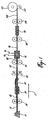
- Figure 1 represents one embodiment of the process of the present invention for producing a multifilament Draw Textured Yarn (DTY) including deposited microcapsules according to the present invention in a textile winder.
- the process steps, as well as the schematic nature of the filaments of the yarn during the processing is represented in Figure 1 .
- the direction of movement of the yarn during processing is indicated by the arrow 2.
- a supply spool 10 of a multi-filament partially oriented yarn (POY) 12 is fed from the spool 10 to a first shaft 20 also called an input feeding shaft or roll, rotating at a given speed. From this shaft 20 the yarn is fed to a second shaft or roll 60, which turns at a higher speed than the first shaft 20.
- POY multi-filament partially oriented yarn
- the yarn 12 is simultaneously drawn, its length is increased and diameter diminished and twisted.
- the yarn 12 is twisted after the first shaft 20 by a friction device, such as a set of spindles or friction discs 50 which produce a twisted yarn 22.
- the yarn 22 enters a heater 30 where its temperature is increased so that the yarn 22 is thermo-fixed (130°C to 500°C).
- the heater 30 is followed immediately by a cooling zone 40 which may be at room temperature or may be cooled below room temperature.
- the cooler 40 has a smooth curved surface which facilitates the cooling and reduces the likelihood of breaking very fine filaments of yarn.
- the yarn 52 leaving the friction discs 50 may in some cases be straightened as represented in the Figure 1 .
- the tension between the second shaft 60 and the first shaft 20 caused by the greater speed of the second shaft 60 causes the filaments of the yarn 22 to be elongated while heated.
- the tension of the drawn yarn 62 leaving the second shaft 60 is lower due to the lower speed of shaft 80 (or the "2 bis" roll) in relation to shaft 60.
- the yarn travels or winds through an opening or passage extending through the body of device 70 in the direction indicated by the arrow 2.
- the filament in yarn 62 are separated as well as, possibly interlaced or intermingled in the device 70, where in a preferred embodiment there is an air jet 72.
- the yarn 62 enters the device 70 where the air jet 72 (at a pressure as much as 100 psi) is directed at the yarn 62 in a perpendicular or nearly perpendicular direction with respect to the of movement of the yarn 2.
- the yarn 62 comes into contact with air vortices produced by the air jet 72 which act as a means of separating of the filaments of the yarn 62 in a preferred embodiment.
- the air jet 72 enters the device 70, through an aperture transverse to the opening through the device 70.
- a gas jet such as the air jet 72
- a gas jet are produced by a gas or fluid passing through an aperture, a hole, or a nozzle, and possibly via other devices such as a valve, which produces a very high velocity gas/fluid stream.
- the air in the air jet 72 may be replaced with another suitable gas or combination of gases such as an inert gas like nitrogen, helium, neon or argon if required.
- the air/gas jet 72 may also be heated.
- the device 70 includes a hole or nozzle for a stream 74 through which suspended microcapsules are injected into the device 70 at the point close to where the filaments have been separated from one another, into individual filaments, while winding through the device 70.
- This nozzle is located along the winding path of the yarn, and is located proximate to a point where the filaments have been separated.
- the nozzle producing the liquid jet 74 is located downstream, with respect to the direction of travel of the yarn 2, of this yarn separating point.
- the microcapsules liquid jet 74 leaves a nozzle intersecting the yarn winding opening, the intersection of liquid nozzle and yarn winding opening is substantially opposite and/or slightly downstream of an aperture for an air jet 72.
- the liquid nozzle and the aperture may both be transverse to the yarn winding opening through the device 70.
- the aperture for the jet 72 and the nozzle for the liquid stream 74 are perpendicular to the wall of the opening of the device.
- the stream or spray 74 of microcapsules will be injected into and adhere to the separated individual filaments and coat the filament surfaces.
- there are two air jets and two liquid jets and each air and liquid jet is in close proximity to one another and are situated along the wall of opening through the device 70.
- the orientation of the nozzles along the wall opening may be directed at the winding yarn so that the jet makes a perpendicular angle to the direction of travel of the yarn 2.
- the angle made between the direction of the liquid jet 74, the air jet 72 when either jet leaves the nozzle in a substantially straight line, and the direction of travel may vary by 30° from the perpendicular and as much as 45° from the perpendicular.
- This braided, interlaced or intermingled and textured yarn 76 thus produced includes microcapsules within the structure, as well as on the external surfaces of the yarn 76.
- the microcapsules are also found within the narrow hollows of the intermingled or entangled filaments. Because the microcapsules make it into these grooves or channels of the specific filaments of yarn, the yarn is expected to retain the microcapsules and therefore the properties of the materials within the microcapsules for a longer period of time, than in processes where the yarn is coated only on the surface.
- Figure 5 is a electro-micrograph of a yarn where the individual filaments include microcapsules.
- the additives may be injected into the yarn directly after the shaft 60 without the aid of an air jet 72. But the use of an air jet improves the process by separating the individual filaments of 52 before inserting the microcapsules.
- the jet 72 separates the filaments to a greater extent than with only un-tensioning due to the effects of the operation of the shafts alone, and is thus a preferred mode of operation for this invention.
- additive, microcapsule and nanocapsule are used interchangeably, each of which can have a single constituent or multiple components.
- the additives are preferably microcapsules in a range of diameter from 0.1 to 1000 ⁇ m, preferably between 0.1 to 200 ⁇ m, and most preferably 0.5 to 20 ⁇ m, where the microcapsules have an outer wall and a central core.
- the wall is adapted to bind to the filaments.
- the outer wall of the microcapsule fuses with the individual filament by the action of heat and/or with the binder.
- the central core of the complete particle or microcapsule may include a substance or material which is chemically, physico-chemically or biologically active or simply cosmetic. These materials may be topical skin lotions or medicines.
- the chemically, physico-chemically or biologically active material enclosed inside of microcapsule may include the following types of substances: bioactive agents, drugs and pharmaceuticals; enzymes; dyes and pigments; fragrances; moisturizing agents; bleaching agents; depilatory agents; UV-block agents; softening agents; elasticity improving agents; flame-, moth-, crease- and soil-proofing agents; water repellent agents; anti-shrinking agents; cross-linking agents; magnetic particles; thermochromic, photochromic, electrochromic, piezorochromic, solvatechromic, carsolchromic materials; insects repellents; pesticides; static electricity-controlling or reducing agents; electrically conductive materials; radar-absorbing materials; reflecting particles; heat-absorbing and/or heat-releasing phase change agents; decontamination agents; zeolites; activated carbon; and combinations of these substances.
- the yarn 76 continues to the third shaft 80 and the fourth shaft (also be called the delivery or nip roll), 100.
- a heater 90 may be included in between the two rolls 80.
- the optional heater 90 may evaporate any solvents or aqueous component injected with the microcapsules suspension and also helps to further bind the microcapsules to the filaments.
- the fourth set of shafts 100 serves to control overfeed in the temperature setting zone, before the yarn 102 is drawn or wound onto the take-up spool 112 with the aid of take-up shaft 110.
- the device 70 has been located directly after the shaft 60 without the inclusion of an air jet, as well as, directly after the second heater 90 and before the nip roll 100. Microcapsules have successfully been applied and inserted into the multi-filaments of the yarn at various locations.
- the deposition process of the present invention requires that the yarn be textured before the separation and deposition occurs.
- the starting yarns may be textured, immediately upstream of the process of the present invention, and this is described in Fig. 2 .
- POY Partially Oriented Yarn
- FOY Fully Oriented Yarn
- LOY Low Oriented Yarn
- more than one spool of POY, FOY, LOY or combinations thereof is fed in a winding machine.
- Each POY or other yarn passes over a heater into an air jet device.
- Figure 2 is an option of texturizing POY into a multi-filament yarn before the deposition of the additive/microcapsule.
- the direction of the movement of the yarn in Figure 2 is indicated by the arrow number 3.
- spools 150, 160
- the filaments are drawn by a second set of shafts (220, 230) at a greater speed through a similar series of steps which include a heating step (190, 200) with the POY.
- These POY yarns can be further textured such that the feed rate of the yarns from the second shafts 220 and 230 are different in the order of -10% to +200% thus the yarn 231 leaving the shaft 230 may be fed at a speed as much as 200% greater than the yarn 221 leaving the shaft 220.
- the yarn 221 is called the core yarn while the yarn 231 is called the effect yarn in entering the air jet device 240 the air jet 242 has a tendency of enveloping the effect yarn 231 over the core yarn 221, to give a multiplicity of loops and thus the POY yarn which was only partially oriented is now a multi-filament yarn ready to have additives incorporated by the process of the present invention through the hole for jet 264.
- the type of process arrangement often includes two stabilizing rollers 250 and 270, which reduce and stabilize the yarn produced to a more uniform thickness.
- the microcapsule jet device 260 optionally including another air jet 262, is placed between the two sets of stabilizing rollers 250 and 270.
- the liquid jet 264 incorporates additives within the yarn, with individual filaments separated by un-tensioning of the yarn or by the action of an air jet.
- the multi-filament yarn leaving the jet device 260 and roller 270, including microcapsules may once again be heated to evaporate the aqueous phase and so as to further adhere the microcapsules to the now multi-filament texturized yarn in heater 280.
- the heater 280 is between rolls 270 and 290. From the roll 290, the yarn is wound onto the take-up spool with the aid of take-up shaft.
- the take-up spool and shaft are not illustrated in Figure 2 .
- Figure 3 represents a tank 300 which includes a mechanically or magnetically driven agitator 310 where the suspension of microcapsules in aqueous phase is prepared.
- the tank 300 may include a means 320 which heat the suspension of particles in a controlled manner.
- the suspension is re-circulated from the tank 300 by means of a pump 330.
- the pump 330 is selected from the group of pumps which are designed to minimize the shear and thus the breakage of microcapsules in suspension.
- the types of pumps applicable are selected from the group consisting of peristaltic, diaphragm, progressing cavity, and centrifugal disc pumps. The skilled practitioner would understand that this group of pumps is not limitative and other pumps minimizing the shearing of microcapsules may be employed.
- the suspension is circulated in a piping or tubing system 332 to the typical jet device 370 where the multi-filament yarn 360 will be intermingled by the action of the air jet 372 and coated by the action of the jet 374 of microcapsules.
- the suspension is not completely consumed by spraying onto the filaments and is collected in a vessel 380 for re-circulation by pump 339 back to the original reservoir 300.
- the suspension of microcapsules may contain components that have a tendency to block jet 374 which requires periodic cleaning or de-blocking of the hole through which liquid jet passes during operation by periodic maintenance. This periodic cleaning may be performed by a mechanical device or through the selection of self-cleaning jets.
- Fig. 4 illustrates a cross sectional view of a preferred embodiment of the present device 470 used to deposit additives such as microcapsules and nano-capsules into the filaments of a textured yarn.
- the device includes a body 400 defining a central opening or hole 405 which passes through the device 470, in a preferred embodiment the hole is cylindrical.
- the hole 405 is adapted to allow: the passage of textured yarn 62 at high speed into and through the opening 405, and the exit of the intermingled yarn 76 at the outlet end of the opening 405.
- the direction of the movement of the yarn 62 through the device 470 is indicated by the arrow 4.
- the wall of opening 405 is intersected by at least one hole for a liquid jet 474, which due to an un-tensioning caused either by the slight reduction of speed through the device, or by the inclusion in a preferred embodiment of an aperture for an gas or air jet 472 which will open the multifilament and allow the deposition of additives within the individual filaments of the yarn 62.
- a liquid jet 474 which due to an un-tensioning caused either by the slight reduction of speed through the device, or by the inclusion in a preferred embodiment of an aperture for an gas or air jet 472 which will open the multifilament and allow the deposition of additives within the individual filaments of the yarn 62.
- Fig. 4 represents a preferred embodiment which includes two liquid holes or nozzles 473, 475, which produce two liquid sprays (or jets) 474, 476.
- the number and placement of liquid holes can be increased or decreased depending on the speed of the yarn through the device 470, and would be understood by a skilled practitioner.
- the hole(s) 473, (475) are liquid nozzle(s) and are located opposite an aperture 471 for the air jet 472 along the wall of the opening.
- the air jet hole 471 and the air jet 472 are once again used to separate the filaments of the yarn.
- This embodiment of the device has mechanical means for cleaning the liquid nozzles by a system of plungers 491 and 493 which scrap any build-up from the top of the liquid holes 473, 475.
- Arrow 495 represents the direction of the movement of the plungers 491, 493. In Fig.
- one of the plungers 491 is in a retracted position, while plunger 493 is in an extended position removing any deposits of additives which may have built up in the hole 475.
- Other means for the cleaning of the nozzles 473, 475 can be envisaged and include the redirection or the addition of a the high pressure air jet towards the top of the liquid jets 473, 475. Many such alternatives are available and known to the skilled practitioner.
- the deposited microcapsules have been represented by varying sized triangles, indicating the incorporation of microcapsules on the surface and within the yarn 76.
- the excess liquid from the jets 474, 476 passes out the end of the device at the outlet end of the device 470.
- This excess is collected in a tank or container 480 and re-circulated back to the liquid nozzles 473, 475 in a manner as represented in Figure 3 .
- of the device 470 is enclosed in a casing, which is designed to collect the excess liquid from the jet 474, 476 and may be under a slight negative pressure so that any vapors can be evacuated from the surroundings and treated.
- microcapsules Before being deposited an aqueous suspension of the microcapsules is required.
- the microcapsules are mixed with various ingredients to produce an aqueous suspension.
- the microcapsules containing a wide variety of products encapsulated within an outer shell typically polymeric in nature, in one embodiment the encapsulated product is a scent of lavender which contains linolyl acetate. Commonly the outer shell is a type of polyurethane or similar compound previously described.
- the suspension in includes; the microcapsules in aqueous suspension; a binder; and a softener typically a silicon micro-emulsion.
- microcapsules, the binder and the softener are added in a ratio that varies from 35:35:30 to 48:48:4 with a preferred embodiment being 45:45:10. These mixtures are then dispersed in aqueous phase in a ratio up to 25 to 30% with a preferred embodiment being between 15 and 20%.
- Example 1 Multifilament (pes) polyester yarn with lavender perfume microcapsules.
- Example 1 describes the production of a yarn that can be used to produce a fabric with a lavender aroma, mainly for underwear and hosiery.
- the multi-filament polyester yarn with a final decitex of 78 and 72 filaments is sprayed with a suspension composed of 85% water, 6.75% of polyurethane binder, 6.75% of concentrated microcapsule solution and 1.5% of a silicone softener.
- the microcapsules used has a mean diameter of 2 microns ( ⁇ m). The deposition / application process was conducted on the false twist texturing machine.
- the speed and other adjustments are standard for a DTY process with the following exceptions: the speed differential between the roll 60, and the rolls 80 of the spraying jet 70. These speeds were adjusted in order to have minimal tension on the yarn 62 and to facilitate the opening of the multifilament. This opening of the multifilament produces a yarn which has the microcapsules within the yarn.
- the speed of the nip rolls 100 is increased to provide more tension on the yarn in order to prevent yarn sticking on the "2 bis" roll, 80.
- the stickiness of the yarns derives from the fresh solution being sprayed thereon.
- the delivery rate of the liquid to the jet 70 is 0.139 ml/min and the air pressure is 20 psi.
- Example 1 The yarn produced in Example 1 was knitted on a "FAK” (Fiber analysis knitter) one feed laboratory knitting machine (Lawson Hemphill Inc.) with a E22 gauge.
- FAM Fiber analysis knitter
- one feed laboratory knitting machine Lawson Hemphill Inc.
- Example 2 Multifilament polyamide (nylon) yarn with citronella (lemon grass) perfume microcapsules.
- the multi-filament nylon yarn with a final decitex of 78 and 68 filaments was sprayed with a suspension composed of 85% water, 4.5% of polyurethane binder, 9% of concentrated microcapsule solution and 1.5% of a silicone softener.
- the microcapsules once again had a mean diameter of 2 microns ( ⁇ m).
- the deposition process was conducted in the same manner, at the same speed and settings as described in Example 1.
- the delivery rate of the liquid to the jet 70 is 0.439 ml/min and the air pressure is 30 psi.
- the deposition of the microcapsules was conducted on a textile winding machine.
- the yarn produced was knitted and compared statistically as in Example 1.
- Example 3 Multifilament yarn polypropylene (pp) with lavender perfume microcapsules.
- the multi-filament- pp (polypropylene) yarn with a final decitex of 78 and 68 filaments was sprayed with the solution composed of 80% water, 9% of polyurethane binder, 9% of concentrated microcapsule solution and 2% of a silicone softener. All components and conditions were maintained as in Examples 1 and 2.
- the delivery rate of the liquid to the jet 70 is 0.781 ml/min and the air pressure is 30 psi.
- Example 3 The yarns produced in Example 3 were knitted in the same manner as in Examples 1 and 2.
- Example 4 used a solution composed of 85% water, 4.5% of acrylic copolymer binder, 9% of concentrated microcapsule solution and 1.5% of a silicone softener and delivery rate of the liquid to the jet 70 was 0.439 ml/min and the air pressure is 30 psi.
- Example 5 a solution composed of 80% water, 9% of polyurethane binder, 9% of concentrated microcapsule solution and 2% of a silicone softener was used, at feed rate of the liquid to the jet 70 of 0.781 ml/min and at an air pressure of 30 psi.
- Example 6 A multifilament polyester (pes) yarn with a final decitex of 156 and 200 filaments was used, and sprayed with the solution composed of 60% water, 18% of polyurethane binder, 18% of concentrated microcapsule solution and 4% of a silicone softener. All the process conditions were maintained as in the preceding Examples. The delivery rate of the liquid to the jet 70 is 2.49 ml/min and the air pressure is 30 psi. The produced yarn was knit as in the previous Examples.
Landscapes
- Engineering & Computer Science (AREA)
- Textile Engineering (AREA)
- Mechanical Engineering (AREA)
- Yarns And Mechanical Finishing Of Yarns Or Ropes (AREA)
- Chemical Or Physical Treatment Of Fibers (AREA)
- Artificial Filaments (AREA)
Claims (24)
- Un procédé permettant le dépôt de microcapsules au sein d'un fil comportant des multi-filaments, comprenant les étapes suivantes :on prépare une suspension aqueuse de microcapsules;on sépare les multi-filaments du fil en filaments individuels tout en enroulant le fil;on injecte la suspension aqueuse de microcapsules sur les filaments individuels; eton fait en sorte que les filaments individuels du fil se referment l'un sur l'autre, de façon à ce que les microcapsules soient confinés au sein des multi-filaments.
- Le procédé de la revendication 1, dans lequel les microcapsules ont un diamètre variant entre 0,1 et 200 µm, et dans lequel les microcapsules comprennent une paroi extérieure et un noyau central.
- Le procédé de la revendication 1, dans lequel on exécute les étapes sur le fil pendant l'opération d'une machine à bobiner le textile.
- Le procédé de la revendication 3, dans lequel la machine à bobiner le textile est choisie parmi le groupe constitué par un bobinoir, une machine à texturer et un retordoir.
- Le procédé de la revendication 4, dans lequel la machine à texturer est une machine à texturer à fausse torsion.
- Le procédé de la revendication 4, dans lequel la machine à texturer est une machine à texturer à l'air.
- Le procédé de la revendication 1, dans lequel la séparation des multi-filaments du fil s'obtient par une relâche de la tension du fil entre deux arbres d'une machine à bobiner le textile.
- Le procédé de la revendication 1, dans lequel la séparation des multi-filaments du fil s'obtient par un jet de gaz propulsé sur le fil.
- Le procédé selon la revendication 1, dans lequel l'injection des microcapsules sur les filaments individuels s'obtient par l'entremise d'un jet de liquide.
- Le procédé selon la revendication 1, dans lequel le fil est choisi parmi le groupe constitué par des polyesters, polyamides, polypropylène, polyéthylène, aramides, les fils synthétiques à multi-filaments et les fils artificiels à multi-filaments.
- Le procédé selon la revendication 1, dans lequel le fil comportant des multi-filaments s'obtient par texturation d'un fil partiellement orienté (POY) ou d'un fil complètement orienté (FOY).
- Le procédé de la revendication 2, dans lequel le noyau central comprend un matériau chimiquement, ou physico-chimiquement ou biologiquement actif, et le matériau est choisi parmi le groupe constitué par des agents bioactifs; des médicaments et des produits pharmaceutiques; des enzymes, des teintures et des pigments; des parfums; des agents hydratants, des agents de blanchiment; des agents dépilatoires; des agents UV-bloquants; des agents adoucissants; des agents d'amélioration de l'élasticité; des agents ignifugeants, antimitages, de protection contre les faux-plis, de protection contre les saletés; des agents hydrofuges; des agents anti-rétrécissement; des agents de réticulation; des particules magnétiques, des matériaux thermochromiques, photochromiques, électrochromiques, piézorochromiques, solvatéchromiques, carsolchromiques; des insectifuges; des pesticides, des agents de contrôle ou de réduction de l'électricité; des matériaux conducteurs de l'électricité, des matériaux absorbants le radar; des particules réfléchissantes, des agents de changement de phase dans l'absorption et/ou la libération de la chaleur; des agents de décontamination; des zéolites; et le charbon actif; et les combinaisons de ces dernières.
- Le procédé de la revendication 2, dans lequel la paroi extérieure est un matériau naturel, semi-synthétique ou synthétique, à masse moléculaire élevée, notamment la gélatine; la gomme arabique, l'agar-agar; l'acide alginique et ses sels; les acides gras, l'alcool cétylique, le collagène; le chitosane; les lécithines; l'albumine, l'amidon, le dextrane; les polypeptides; la cellulose et la cellulose chimiquement modifiée; les polyacrylates, l'alcool polyvinylique; le polyvinyl pyrrolidone; le polyuréthanne; les polyoléfines; les polyamides, un aminoplaste; les polyesters; les polysaccharides, les résines siliconées; les résines époxy et les résines à base de formaldéhyde.
- Un dispositif permettant de dépôt de microcapsules au sein d'un fil comportant une pluralité de filaments, le dispositif comprenant :une bobine d'alimentation,une bobine réceptrice enroulant le fil selon une première direction entre la bobine d'alimentation et la bobine réceptrice,un moyen pour séparer le fil en au moins un point de séparation disposé entre la bobine d'alimentation et la bobine réceptrice, le moyen pour séparer le fil exposant ainsi les filaments, etau moins une buse prévue au voisinage du point de séparation, la au moins une buse injectant un liquide sur les filaments selon une seconde direction transversale par rapport à la première direction, les microcapsules étant suspendues dans le liquide, faisant en sorte de procéder à l'injection des microcapsules.
- Le dispositif de la revendication 14, dans lequel la au moins une buse est située en aval du point de séparation.
- Le dispositif de la revendication 14, comprenant :un corps disposé entre les deux bobines, le corps définissantune ouverture à travers laquelle le fil s'enroule selon la première direction etla au moins une buse étant orienté pour croiser l'ouverture, et faisant ainsi parvenir le liquide comportant les microcapsules vers le fil.
- Le dispositif de la revendication 14, dans lequel le moyen pour séparer le fil comprendun premier et un second arbre, les arbres étant disposés entre la bobine d'alimentation et la bobine réceptrice,le premier arbre enroulant le fil à une première vitesse etle second arbre enroulant le fil parvenant du premier arbre à une seconde vitesse de rotation inférieure à la première vitesse, faisant en sorte de produire une relâche de la tension du fil.
- Le dispositif de la revendication 16, dans lequel le moyen pour séparer le fil comprendau moins une ouverture définie dans le corps, l'ouverture étant reliée à une alimentation de gaz sous pression, le passage du gaz à travers l'ouverture produisant un jet de gaz projeté sur le fil en direction transversale par rapport à la première direction.
- Le dispositif de la revendication 18, dans lequel l'ouverture projette le jet de gaz de façon à produire un angle lorsqu'il croise la première direction, l'angle variantentre en angle perpendiculaire à la première direction,et 30° par rapport à la perpendiculaire à la première direction.
- Le dispositif de la revendication 18, dans lequel la au moins une buse, comporte deux buses.
- Un fil multi-filament comportant un périmètre en coupe, le fil comprenant :des filaments individuels reliés entre eux pour constituer le fil; etdes microcapsules, ayant un diamètre variant entre 0,1 et 200 µm, prévues sur les filaments individuels à l'intérieur du périmètre du fil.
- Le fil de la revendication 21, dans lequel les microcapsules comprennent une paroi extérieure et un noyau central.
- Le fil de la revendication 22, dans lequel le noyau central comprend un matériau chimiquement, physico-chimiquement ou biologiquement actif et le matériau étant choisi parmi le groupe constitué par des agents bioactifs; des médicaments et des produits pharmaceutiques; des enzymes, des teintures et des pigments; des parfums; des agents hydratants, des agents de blanchiment; des agents dépilatoires; des agents UV-bloquants; des agents adoucissants; des agents d'amélioration de l'élasticité; des agents ignifugeants, antimitages, de protection contre les faux-plis, de protection contre les saletés; des agents hydrofuges; des agents anti-rétrécissement; des agents de réticulation; des particules magnétiques, des matériaux thermochromiques, photochromiques, électrochromiques, piézorochromiques, solvatéchromiques, carsolchromiques; des insectifuges; des pesticides, des agents de contrôle ou de réduction de l'électricité; des matériaux conducteurs de l'électricité, des matériaux absorbants le radar; des particules réfléchissantes, des agents de changement de phase dans l'absorption et/ou la libération de la chaleur; des agents de décontamination; des zéolites; et le charbon actif; et les combinaisons de ces dernières.
- Le fil de la revendication 23, dans lequel le fil est choisi parmi le groupe constitué par des polyesters, polyamides, polypropylène, polyéthylène, aramides, les fils synthétiques à multi-filaments et les fils artificiels à multi-filaments.
Applications Claiming Priority (2)
| Application Number | Priority Date | Filing Date | Title |
|---|---|---|---|
| US57494204P | 2004-05-28 | 2004-05-28 | |
| US574942P | 2004-05-28 |
Publications (3)
| Publication Number | Publication Date |
|---|---|
| EP1609896A2 EP1609896A2 (fr) | 2005-12-28 |
| EP1609896A3 EP1609896A3 (fr) | 2006-12-06 |
| EP1609896B1 true EP1609896B1 (fr) | 2008-07-30 |
Family
ID=35124322
Family Applications (1)
| Application Number | Title | Priority Date | Filing Date |
|---|---|---|---|
| EP05253341A Expired - Lifetime EP1609896B1 (fr) | 2004-05-28 | 2005-05-31 | Procédé pour la déposition de microcapsules dans un fil multifilament et produits correspondants |
Country Status (4)
| Country | Link |
|---|---|
| US (1) | US20050262646A1 (fr) |
| EP (1) | EP1609896B1 (fr) |
| AT (1) | ATE403021T1 (fr) |
| DE (1) | DE602005008513D1 (fr) |
Families Citing this family (14)
| Publication number | Priority date | Publication date | Assignee | Title |
|---|---|---|---|---|
| GB2426255B (en) * | 2005-05-16 | 2009-09-23 | Univ Manchester | Operative devices |
| US20100012017A1 (en) * | 2006-09-27 | 2010-01-21 | Luvgear Inc. | Device and method for identifying a change in a predetermined condition |
| JP5822289B2 (ja) * | 2010-08-23 | 2015-11-24 | 倉敷紡績株式会社 | 詰め物体 |
| CN107130333B (zh) * | 2017-06-19 | 2019-05-07 | 山东大学 | 一种海藻酸与壳聚糖混编纤维及其制备方法 |
| CA3128516C (fr) | 2019-02-14 | 2024-03-12 | Cyclopure, Inc. | Materiaux polymeres de cyclodextrine porteurs de charge et leurs procedes de preparation et d'utilisation |
| US11001645B2 (en) | 2019-02-14 | 2021-05-11 | Cyclopure, Inc. | Charge-bearing cyclodextrin polymeric materials and methods of making and using same |
| CN110129942B (zh) * | 2019-06-14 | 2020-09-25 | 武汉纺织大学 | 弹性导电纱线及其制备方法 |
| CN110983530B (zh) * | 2019-11-22 | 2021-03-26 | 武汉纺织大学 | 一种摩擦纺相变抗静电复合纱及其制备方法 |
| CN111020775B (zh) * | 2019-11-22 | 2021-03-26 | 武汉纺织大学 | 一种摩擦纺相变导电复合纱及其制备方法 |
| CN111155218B (zh) * | 2019-12-24 | 2021-12-17 | 浙江银汇高纤材料股份有限公司 | 一种化纤长丝的后处理设备 |
| WO2022032440A1 (fr) * | 2020-08-10 | 2022-02-17 | 深圳先进技术研究院 | Microsphère composite, procédé de préparation et application associés |
| CN113338045A (zh) * | 2021-05-07 | 2021-09-03 | 广东前进牛仔布有限公司 | 一种环保的纱线浆染方法、微胶囊结构、纱线及面料 |
| WO2024151850A1 (fr) | 2023-01-12 | 2024-07-18 | Cyclopure, Inc. | Régénération d'adsorbants polymères de cyclodextrine |
| CN116905147B (zh) * | 2023-04-25 | 2026-02-27 | 东华大学 | 一种复合管状结构拉胀纱线的加工装置、方法及用途 |
Family Cites Families (26)
| Publication number | Priority date | Publication date | Assignee | Title |
|---|---|---|---|---|
| US2730455A (en) * | 1952-10-30 | 1956-01-10 | Carl C Swann | Method of coating fibers, threads, and/or filamentary material |
| US3479811A (en) * | 1967-11-29 | 1969-11-25 | Dow Chemical Co | Yarn and method of making the same |
| US3586560A (en) * | 1968-06-17 | 1971-06-22 | Eastman Kodak Co | Method of making a fiber-filled thermoplastic article |
| US3648650A (en) * | 1969-06-02 | 1972-03-14 | Burlington Industries Inc | Yarn coating system |
| CA935955A (en) * | 1969-08-22 | 1973-10-30 | Kanegafuchi Boseki Kabushiki Kaisha | Process of treating fibrous articles with microcapsules containing hydrophobic treating agent |
| JPS5022613B1 (fr) * | 1971-06-29 | 1975-08-01 | ||
| GB1565195A (en) * | 1975-11-07 | 1980-04-16 | Ici Ltd | Method for producing fibre-reinforced thermoplastic polymer |
| CA1240883A (fr) | 1985-01-30 | 1988-08-23 | Norikazu Nakasuji | Materiau textile thermochrome |
| JPS6452837A (en) * | 1987-05-18 | 1989-02-28 | Sumitomo Chemical Co | Method for opening fiber |
| US4873937A (en) * | 1988-01-28 | 1989-10-17 | Nordson Corporation | Method and apparatus for spraying powder into a continuous tow |
| US4882220A (en) * | 1988-02-02 | 1989-11-21 | Kanebo, Ltd. | Fibrous structures having a durable fragrance |
| JPH02200602A (ja) | 1989-01-30 | 1990-08-08 | Kuraray Co Ltd | 防虫繊維およびその製造方法 |
| US5232769A (en) * | 1989-08-01 | 1993-08-03 | Kanebo, Ltd. | Microcapsule, treating liquids containing the same, and textile structure having microcapsules adhering thereto |
| US5225018A (en) * | 1989-11-08 | 1993-07-06 | Fiberweb North America, Inc. | Method and apparatus for providing uniformly distributed filaments from a spun filament bundle and spunbonded fabric obtained therefrom |
| US5308563A (en) * | 1992-08-31 | 1994-05-03 | Basf Corporation | Process for producing antistatic yarns |
| US5941256A (en) * | 1996-12-24 | 1999-08-24 | Gillette Canada Inc. | Dental hygiene article |
| JPH1112953A (ja) | 1997-06-30 | 1999-01-19 | Lion Corp | 繊維処理用マイクロカプセル及びマイクロカプセル付着繊維 |
| FR2781238B1 (fr) | 1998-07-20 | 2000-10-06 | Ted Lapidus | Article textile ou vestimentaire ou de toilette et soin du corps, porteur de microcapsules, et procedes pour sa realisation |
| JP2000178873A (ja) | 1998-12-15 | 2000-06-27 | Teijin Ltd | 芳香性及び難燃性を有するポリエステル繊維布帛 |
| AU7136000A (en) * | 1999-07-19 | 2001-02-05 | Avantgarb, Llc | Nanoparticle-based permanent treatments for textiles |
| KR20020056779A (ko) | 2000-12-29 | 2002-07-10 | 이원목, 김창복 | 향기 코팅 조성물을 이용하여 제조한 향기나는 원단 및그의 제조 방법 |
| DE10106596A1 (de) | 2001-02-09 | 2002-08-22 | Deotexis Inc | Verfahren zum bereichsweisen Bedrucken eines Textilmaterials |
| KR20010069654A (ko) | 2001-04-25 | 2001-07-25 | 이상민 | 향기원단 코팅방법 |
| KR20020082692A (ko) | 2001-04-25 | 2002-10-31 | 문상배 | 분무형 캡슐 향 조성물 및 그의 제조방법 |
| US20020166628A1 (en) * | 2001-05-09 | 2002-11-14 | Larry Harris | Process for applying microcapsules to textile materials and products formed by the process |
| DE50204522D1 (de) | 2002-04-30 | 2005-11-17 | Cognis Ip Man Gmbh | Mit Mikrokapseln ausgerüstete Fasern und textile Flächengebilde |
-
2005
- 2005-05-27 US US11/138,859 patent/US20050262646A1/en not_active Abandoned
- 2005-05-31 DE DE602005008513T patent/DE602005008513D1/de not_active Expired - Lifetime
- 2005-05-31 EP EP05253341A patent/EP1609896B1/fr not_active Expired - Lifetime
- 2005-05-31 AT AT05253341T patent/ATE403021T1/de not_active IP Right Cessation
Also Published As
| Publication number | Publication date |
|---|---|
| EP1609896A2 (fr) | 2005-12-28 |
| ATE403021T1 (de) | 2008-08-15 |
| US20050262646A1 (en) | 2005-12-01 |
| EP1609896A3 (fr) | 2006-12-06 |
| DE602005008513D1 (de) | 2008-09-11 |
Similar Documents
| Publication | Publication Date | Title |
|---|---|---|
| EP1609896B1 (fr) | Procédé pour la déposition de microcapsules dans un fil multifilament et produits correspondants | |
| CA2038542C (fr) | Dispositif et procede d'amalgame de fils multiples continus | |
| US6253431B1 (en) | Air opening jet apparatus | |
| Muñoz et al. | Functional textiles for skin care active substance encapsulation | |
| JP6776938B2 (ja) | 嵩高糸の製造方法 | |
| US4265082A (en) | Spun-like yarn and a process for manufacturing the same | |
| US3969885A (en) | Method for manufacturing a textured yarn | |
| US5307616A (en) | Method to manufacture a slub yarn | |
| WO2007053429A2 (fr) | Procédé servant à enrober des fibres et des fils et produits enrobés formés à partir de celui-ci | |
| JPS59173335A (ja) | 糸の製造方法 | |
| WO2004053213A1 (fr) | Traitement de fils de filaments permettant de fournir a ces derniers les caracteristiques d'un file, fils susmentionnes et tissus fabriques a partir de ces derniers | |
| JPH02118131A (ja) | 放射線不透過性糸 | |
| JP4245952B2 (ja) | 頭飾用再生コラーゲン繊維の製造方法及び連続乾燥装置 | |
| CA2051856A1 (fr) | Fils composites a brins courts et longs, ainsi que procede et appareil de fabrication | |
| US5746046A (en) | Method for forming comingled composite yarn | |
| JP6926667B2 (ja) | 嵩高糸 | |
| WO1998028482A1 (fr) | Fil a coudre enduit d'un liant | |
| JPS61174438A (ja) | スラブヤ−ン及びその製造方法 | |
| JPS61502475A (ja) | 糸条への液体の付与方法並びに装置 | |
| JPS6319610B2 (fr) | ||
| EP0504445B1 (fr) | Dispositif et procédé pour mélanger des fils multifilament continus | |
| WO1998022224A9 (fr) | Procede de traitement d'une matiere textile mobile | |
| WO1998028483A1 (fr) | Filaments torsades, teintes et tisses | |
| WO1998022224A1 (fr) | Procede de traitement d'une matiere textile mobile | |
| JPH0232370B2 (ja) | Tokushuhoriesuterukakoitonoseizoho |
Legal Events
| Date | Code | Title | Description |
|---|---|---|---|
| PUAI | Public reference made under article 153(3) epc to a published international application that has entered the european phase |
Free format text: ORIGINAL CODE: 0009012 |
|
| AK | Designated contracting states |
Kind code of ref document: A2 Designated state(s): AT BE BG CH CY CZ DE DK EE ES FI FR GB GR HU IE IS IT LI LT LU MC NL PL PT RO SE SI SK TR |
|
| AX | Request for extension of the european patent |
Extension state: AL BA HR LV MK YU |
|
| PUAL | Search report despatched |
Free format text: ORIGINAL CODE: 0009013 |
|
| AK | Designated contracting states |
Kind code of ref document: A3 Designated state(s): AT BE BG CH CY CZ DE DK EE ES FI FR GB GR HU IE IS IT LI LT LU MC NL PL PT RO SE SI SK TR |
|
| AX | Request for extension of the european patent |
Extension state: AL BA HR LV MK YU |
|
| 17P | Request for examination filed |
Effective date: 20070601 |
|
| AKX | Designation fees paid |
Designated state(s): AT BE BG CH CY CZ DE DK EE ES FI FR GB GR HU IE IS IT LI LT LU MC NL PL PT RO SE SI SK TR |
|
| GRAP | Despatch of communication of intention to grant a patent |
Free format text: ORIGINAL CODE: EPIDOSNIGR1 |
|
| GRAC | Information related to communication of intention to grant a patent modified |
Free format text: ORIGINAL CODE: EPIDOSCIGR1 |
|
| GRAS | Grant fee paid |
Free format text: ORIGINAL CODE: EPIDOSNIGR3 |
|
| GRAA | (expected) grant |
Free format text: ORIGINAL CODE: 0009210 |
|
| AK | Designated contracting states |
Kind code of ref document: B1 Designated state(s): AT BE BG CH CY CZ DE DK EE ES FI FR GB GR HU IE IS IT LI LT LU MC NL PL PT RO SE SI SK TR |
|
| REG | Reference to a national code |
Ref country code: GB Ref legal event code: FG4D |
|
| REG | Reference to a national code |
Ref country code: CH Ref legal event code: EP |
|
| REF | Corresponds to: |
Ref document number: 602005008513 Country of ref document: DE Date of ref document: 20080911 Kind code of ref document: P |
|
| REG | Reference to a national code |
Ref country code: IE Ref legal event code: FG4D |
|
| PG25 | Lapsed in a contracting state [announced via postgrant information from national office to epo] |
Ref country code: LT Free format text: LAPSE BECAUSE OF FAILURE TO SUBMIT A TRANSLATION OF THE DESCRIPTION OR TO PAY THE FEE WITHIN THE PRESCRIBED TIME-LIMIT Effective date: 20080730 Ref country code: IS Free format text: LAPSE BECAUSE OF FAILURE TO SUBMIT A TRANSLATION OF THE DESCRIPTION OR TO PAY THE FEE WITHIN THE PRESCRIBED TIME-LIMIT Effective date: 20081130 Ref country code: NL Free format text: LAPSE BECAUSE OF FAILURE TO SUBMIT A TRANSLATION OF THE DESCRIPTION OR TO PAY THE FEE WITHIN THE PRESCRIBED TIME-LIMIT Effective date: 20080730 |
|
| PG25 | Lapsed in a contracting state [announced via postgrant information from national office to epo] |
Ref country code: PT Free format text: LAPSE BECAUSE OF FAILURE TO SUBMIT A TRANSLATION OF THE DESCRIPTION OR TO PAY THE FEE WITHIN THE PRESCRIBED TIME-LIMIT Effective date: 20081230 Ref country code: SI Free format text: LAPSE BECAUSE OF FAILURE TO SUBMIT A TRANSLATION OF THE DESCRIPTION OR TO PAY THE FEE WITHIN THE PRESCRIBED TIME-LIMIT Effective date: 20080730 Ref country code: AT Free format text: LAPSE BECAUSE OF FAILURE TO SUBMIT A TRANSLATION OF THE DESCRIPTION OR TO PAY THE FEE WITHIN THE PRESCRIBED TIME-LIMIT Effective date: 20080730 Ref country code: BG Free format text: LAPSE BECAUSE OF FAILURE TO SUBMIT A TRANSLATION OF THE DESCRIPTION OR TO PAY THE FEE WITHIN THE PRESCRIBED TIME-LIMIT Effective date: 20081030 Ref country code: ES Free format text: LAPSE BECAUSE OF FAILURE TO SUBMIT A TRANSLATION OF THE DESCRIPTION OR TO PAY THE FEE WITHIN THE PRESCRIBED TIME-LIMIT Effective date: 20081110 Ref country code: FI Free format text: LAPSE BECAUSE OF FAILURE TO SUBMIT A TRANSLATION OF THE DESCRIPTION OR TO PAY THE FEE WITHIN THE PRESCRIBED TIME-LIMIT Effective date: 20080730 |
|
| PG25 | Lapsed in a contracting state [announced via postgrant information from national office to epo] |
Ref country code: BE Free format text: LAPSE BECAUSE OF FAILURE TO SUBMIT A TRANSLATION OF THE DESCRIPTION OR TO PAY THE FEE WITHIN THE PRESCRIBED TIME-LIMIT Effective date: 20080730 |
|
| PG25 | Lapsed in a contracting state [announced via postgrant information from national office to epo] |
Ref country code: DK Free format text: LAPSE BECAUSE OF FAILURE TO SUBMIT A TRANSLATION OF THE DESCRIPTION OR TO PAY THE FEE WITHIN THE PRESCRIBED TIME-LIMIT Effective date: 20080730 Ref country code: EE Free format text: LAPSE BECAUSE OF FAILURE TO SUBMIT A TRANSLATION OF THE DESCRIPTION OR TO PAY THE FEE WITHIN THE PRESCRIBED TIME-LIMIT Effective date: 20080730 |
|
| PG25 | Lapsed in a contracting state [announced via postgrant information from national office to epo] |
Ref country code: SK Free format text: LAPSE BECAUSE OF FAILURE TO SUBMIT A TRANSLATION OF THE DESCRIPTION OR TO PAY THE FEE WITHIN THE PRESCRIBED TIME-LIMIT Effective date: 20080730 Ref country code: RO Free format text: LAPSE BECAUSE OF FAILURE TO SUBMIT A TRANSLATION OF THE DESCRIPTION OR TO PAY THE FEE WITHIN THE PRESCRIBED TIME-LIMIT Effective date: 20080730 Ref country code: CZ Free format text: LAPSE BECAUSE OF FAILURE TO SUBMIT A TRANSLATION OF THE DESCRIPTION OR TO PAY THE FEE WITHIN THE PRESCRIBED TIME-LIMIT Effective date: 20080730 |
|
| PLBE | No opposition filed within time limit |
Free format text: ORIGINAL CODE: 0009261 |
|
| STAA | Information on the status of an ep patent application or granted ep patent |
Free format text: STATUS: NO OPPOSITION FILED WITHIN TIME LIMIT |
|
| 26N | No opposition filed |
Effective date: 20090506 |
|
| PG25 | Lapsed in a contracting state [announced via postgrant information from national office to epo] |
Ref country code: MC Free format text: LAPSE BECAUSE OF NON-PAYMENT OF DUE FEES Effective date: 20090531 |
|
| REG | Reference to a national code |
Ref country code: CH Ref legal event code: PL |
|
| GBPC | Gb: european patent ceased through non-payment of renewal fee |
Effective date: 20090531 |
|
| PG25 | Lapsed in a contracting state [announced via postgrant information from national office to epo] |
Ref country code: LI Free format text: LAPSE BECAUSE OF NON-PAYMENT OF DUE FEES Effective date: 20090531 Ref country code: CH Free format text: LAPSE BECAUSE OF NON-PAYMENT OF DUE FEES Effective date: 20090531 Ref country code: SE Free format text: LAPSE BECAUSE OF FAILURE TO SUBMIT A TRANSLATION OF THE DESCRIPTION OR TO PAY THE FEE WITHIN THE PRESCRIBED TIME-LIMIT Effective date: 20081030 |
|
| REG | Reference to a national code |
Ref country code: IE Ref legal event code: MM4A |
|
| PG25 | Lapsed in a contracting state [announced via postgrant information from national office to epo] |
Ref country code: IE Free format text: LAPSE BECAUSE OF NON-PAYMENT OF DUE FEES Effective date: 20090531 |
|
| PG25 | Lapsed in a contracting state [announced via postgrant information from national office to epo] |
Ref country code: GB Free format text: LAPSE BECAUSE OF NON-PAYMENT OF DUE FEES Effective date: 20090531 Ref country code: PL Free format text: LAPSE BECAUSE OF FAILURE TO SUBMIT A TRANSLATION OF THE DESCRIPTION OR TO PAY THE FEE WITHIN THE PRESCRIBED TIME-LIMIT Effective date: 20080730 |
|
| PG25 | Lapsed in a contracting state [announced via postgrant information from national office to epo] |
Ref country code: GR Free format text: LAPSE BECAUSE OF FAILURE TO SUBMIT A TRANSLATION OF THE DESCRIPTION OR TO PAY THE FEE WITHIN THE PRESCRIBED TIME-LIMIT Effective date: 20081031 |
|
| PG25 | Lapsed in a contracting state [announced via postgrant information from national office to epo] |
Ref country code: IT Free format text: LAPSE BECAUSE OF NON-PAYMENT OF DUE FEES Effective date: 20090531 |
|
| PG25 | Lapsed in a contracting state [announced via postgrant information from national office to epo] |
Ref country code: LU Free format text: LAPSE BECAUSE OF NON-PAYMENT OF DUE FEES Effective date: 20090531 |
|
| PG25 | Lapsed in a contracting state [announced via postgrant information from national office to epo] |
Ref country code: HU Free format text: LAPSE BECAUSE OF FAILURE TO SUBMIT A TRANSLATION OF THE DESCRIPTION OR TO PAY THE FEE WITHIN THE PRESCRIBED TIME-LIMIT Effective date: 20090131 |
|
| PGFP | Annual fee paid to national office [announced via postgrant information from national office to epo] |
Ref country code: FR Payment date: 20110610 Year of fee payment: 7 |
|
| PGRI | Patent reinstated in contracting state [announced from national office to epo] |
Ref country code: IT Effective date: 20110616 |
|
| PG25 | Lapsed in a contracting state [announced via postgrant information from national office to epo] |
Ref country code: TR Free format text: LAPSE BECAUSE OF FAILURE TO SUBMIT A TRANSLATION OF THE DESCRIPTION OR TO PAY THE FEE WITHIN THE PRESCRIBED TIME-LIMIT Effective date: 20080730 |
|
| PG25 | Lapsed in a contracting state [announced via postgrant information from national office to epo] |
Ref country code: CY Free format text: LAPSE BECAUSE OF FAILURE TO SUBMIT A TRANSLATION OF THE DESCRIPTION OR TO PAY THE FEE WITHIN THE PRESCRIBED TIME-LIMIT Effective date: 20080730 |
|
| PGFP | Annual fee paid to national office [announced via postgrant information from national office to epo] |
Ref country code: IT Payment date: 20110530 Year of fee payment: 7 |
|
| PGFP | Annual fee paid to national office [announced via postgrant information from national office to epo] |
Ref country code: DE Payment date: 20110727 Year of fee payment: 7 |
|
| PG25 | Lapsed in a contracting state [announced via postgrant information from national office to epo] |
Ref country code: IT Free format text: LAPSE BECAUSE OF NON-PAYMENT OF DUE FEES Effective date: 20120531 |
|
| REG | Reference to a national code |
Ref country code: FR Ref legal event code: ST Effective date: 20130131 |
|
| REG | Reference to a national code |
Ref country code: DE Ref legal event code: R119 Ref document number: 602005008513 Country of ref document: DE Effective date: 20121201 |
|
| PG25 | Lapsed in a contracting state [announced via postgrant information from national office to epo] |
Ref country code: FR Free format text: LAPSE BECAUSE OF NON-PAYMENT OF DUE FEES Effective date: 20120531 |
|
| PG25 | Lapsed in a contracting state [announced via postgrant information from national office to epo] |
Ref country code: DE Free format text: LAPSE BECAUSE OF NON-PAYMENT OF DUE FEES Effective date: 20121201 |