EP1609940B1 - Abfallsicherheitsvorrichtung eines Rollvorhangs - Google Patents
Abfallsicherheitsvorrichtung eines Rollvorhangs Download PDFInfo
- Publication number
- EP1609940B1 EP1609940B1 EP05013407A EP05013407A EP1609940B1 EP 1609940 B1 EP1609940 B1 EP 1609940B1 EP 05013407 A EP05013407 A EP 05013407A EP 05013407 A EP05013407 A EP 05013407A EP 1609940 B1 EP1609940 B1 EP 1609940B1
- Authority
- EP
- European Patent Office
- Prior art keywords
- rocking
- flap
- lever
- notch
- apron
- Prior art date
- Legal status (The legal status is an assumption and is not a legal conclusion. Google has not performed a legal analysis and makes no representation as to the accuracy of the status listed.)
- Expired - Lifetime
Links
Images





Classifications
-
- E—FIXED CONSTRUCTIONS
- E06—DOORS, WINDOWS, SHUTTERS, OR ROLLER BLINDS IN GENERAL; LADDERS
- E06B—FIXED OR MOVABLE CLOSURES FOR OPENINGS IN BUILDINGS, VEHICLES, FENCES OR LIKE ENCLOSURES IN GENERAL, e.g. DOORS, WINDOWS, BLINDS, GATES
- E06B9/00—Screening or protective devices for wall or similar openings, with or without operating or securing mechanisms; Closures of similar construction
- E06B9/56—Operating, guiding or securing devices or arrangements for roll-type closures; Spring drums; Tape drums; Counterweighting arrangements therefor
- E06B9/80—Safety measures against dropping or unauthorised opening; Braking or immobilising devices; Devices for limiting unrolling
- E06B9/82—Safety measures against dropping or unauthorised opening; Braking or immobilising devices; Devices for limiting unrolling automatic
- E06B9/84—Safety measures against dropping or unauthorised opening; Braking or immobilising devices; Devices for limiting unrolling automatic against dropping
-
- E—FIXED CONSTRUCTIONS
- E05—LOCKS; KEYS; WINDOW OR DOOR FITTINGS; SAFES
- E05D—HINGES OR SUSPENSION DEVICES FOR DOORS, WINDOWS OR WINGS
- E05D13/00—Accessories for sliding or lifting wings, e.g. pulleys, safety catches
- E05D13/003—Anti-dropping devices
-
- E—FIXED CONSTRUCTIONS
- E05—LOCKS; KEYS; WINDOW OR DOOR FITTINGS; SAFES
- E05Y—INDEXING SCHEME ASSOCIATED WITH SUBCLASSES E05D AND E05F, RELATING TO CONSTRUCTION ELEMENTS, ELECTRIC CONTROL, POWER SUPPLY, POWER SIGNAL OR TRANSMISSION, USER INTERFACES, MOUNTING OR COUPLING, DETAILS, ACCESSORIES, AUXILIARY OPERATIONS NOT OTHERWISE PROVIDED FOR, APPLICATION THEREOF
- E05Y2900/00—Application of doors, windows, wings or fittings thereof
-
- E—FIXED CONSTRUCTIONS
- E05—LOCKS; KEYS; WINDOW OR DOOR FITTINGS; SAFES
- E05Y—INDEXING SCHEME ASSOCIATED WITH SUBCLASSES E05D AND E05F, RELATING TO CONSTRUCTION ELEMENTS, ELECTRIC CONTROL, POWER SUPPLY, POWER SIGNAL OR TRANSMISSION, USER INTERFACES, MOUNTING OR COUPLING, DETAILS, ACCESSORIES, AUXILIARY OPERATIONS NOT OTHERWISE PROVIDED FOR, APPLICATION THEREOF
- E05Y2900/00—Application of doors, windows, wings or fittings thereof
- E05Y2900/10—Application of doors, windows, wings or fittings thereof for buildings or parts thereof
- E05Y2900/106—Application of doors, windows, wings or fittings thereof for buildings or parts thereof for garages
Definitions
- the present invention relates to an anti-fall device of a flexible structure closing apron capable of being wound around a substantially cylindrical support system and mounted to rotate around a fixed shaft, generally above an opening to condemn.
- the invention finds a particularly advantageous, but not exclusive, application in the field of vertical erasure closures equipping the accesses of industrial and commercial buildings.
- curtains or apron more generally designate any means capable of closing an opening.
- the winding of the deck is traditionally performed around at least one spool mounted to rotate on said fixed shaft.
- Each coil is also connected to the fixed shaft by means of a spiral-type compensation spring, wound inside said coil itself.
- This elastic return means is responsible for at least partially counterbalancing the weight of the deck by restoring during the opening phase, the energy stored as torque during the closing phase.
- roller curtains around a fixed shaft are subject to a number of regulatory and prescriptive requirements.
- the French standard NF P 25-362 replaced by the European standard EN 12604: 2000, having the status of a French standard, taking effect on January 20, 2001, concerns the safety of users in case of failure of the closing.
- an apron has a relatively large weight, generally ranging from several tens to several hundred kilograms. Combined with a high fall speed, this mass is a real danger for users.
- the outer end of the compensation spring is integral with the locking element which is mounted movably in displacement on the corresponding coil, the locking element being able to move in the direction of a static member integral with the fixed shaft. to cooperate by locking with a stop portion of said static member, said locking member being held away from the static member by the restoring force exerted by the compensation spring.
- the compensation spring is the only part controlling the immobilization or displacement of the locking element relative to the coil. In other words, it alone ensures the immobilisation of the blocking element in the passive position, it also controls only the movement towards the static body, and finally it guarantees only the maintenance in the active position; the passive and active positions being those in which said blocking element and said static body are respectively at a distance and in contact with each other.
- the position of the locking element with respect to the static member therefore depends solely and especially directly on the state of the compensation spring.
- the compensation spring Under normal conditions of use, the compensation spring is constantly stretched due to excessive winding of the coil constituting it, and this regardless of the position of the deck. As also its inner end is fixed, the restoring force is felt at its outer end. It is indeed the only one likely to move, for the double reason that it is secured to the locking element mounted movably moving on the coil on the one hand, and that said coil is itself mounted mobile in rotation around the fixed shaft on the other hand.
- the only restoring force thus makes it possible to advantageously maintain the blocking element in the passive position, that is to say at a distance from the static body. This balance remains perfectly stable as long as the compensation spring retains its original mechanical properties.
- the compensation spring When a failure occurs at the compensation spring, the break occurs systematically at the point where the stresses are maximum, that is to say where the curvature is the strongest.
- the part concerned corresponds, of course, to the internal end of the compensation spring, and more generally to the entire zone located near the attachment point on the fixed shaft. The compensation spring is thus released from the inside, from any mechanical stress so that the restoring force disappears.
- the compensation spring Since the compensation spring is wound on itself when the closure functions normally, the volume it occupies inside the coil is very much lower than that which it has at rest, that is to say when not subject to any winding stress. Also, after rupture, it will tend to resume naturally its original form. In case of failure, there is consequently a substantially radial expansion of the compensation spring which tends to deviate as much as possible from the axis around which it was wound. This movement continues until the deployment of the spring is stopped, due to the limited space inside the coil.
- the locking element When no longer subjected to the restoring force exerted by the compensation spring, the locking element is therefore free to leave its passive position and move relative to the coil on which it is mounted, in the direction of the static organ. This obviously implies that it can be driven on the move through a moving body. This is precisely what happens when the compensation spring breaks then animates the double movement of radial extension and rotation previously described. The locking element, secured to the outer end of the compensation spring, is then moved to the active position in which it cooperates by locking with the static member.
- the locking element cooperating with the outer end of the compensation spring is rotatably mounted on the coil and is constituted by an axis on which is freely hooked the free end of the spring, said axis passing through the coil and having at one of its ends opening therefrom a shutter which is integral with it and which is intended to come into contact with the static body by tilting when the spring breaks.
- the curtain is manually operable in recovery, excluding any action downhill. Indeed, the descent is possible only by unlocking the locking member, but the adverse consequence would be to lower the curtain of the entire height separating it with the ground, without limitation of its stroke to 30 cm. The intervention of a specialist is then necessary.
- the invention relates to an anti-fall device of a closing apron for being wound around at least one spool mounted to rotate on a fixed shaft and connected thereto via a compensation spring wound on itself between two blanks of the coil and whose inner end is integral with the shaft, while its outer end cooperates with a locking element mounted to move on said coil so that that in case of failure of the compensation spring, said element comes to cooperate by locking with a stop portion of a static member integral with the fixed shaft and therefore of the apron, said locking member being rotatably mounted on the coil and constituted by an axis on which is freely hooked the free end of the spring, said axis passing through the coil and having at one of its ends opening therefrom a shutter which is integral therewith and which is intended to come into contact with the static body by tilting, upon rupture of the spring, characterized in that the static abutment member of the locking flap is constituted by an outer plate fixed on the shaft, concentrically to this one and to a flan of the coil located opposite,
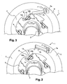
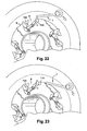
- the device 1 generally designated in the figures makes it possible to prevent the fall of a closing apron (not shown).
- the blocking element 7 of the anti-fall device is rotatably mounted on the coil 2 and is constituted by an axis 7a on which is freely hooked the free end of the spring, said axis 7a passing through the coil 2 and having at one of its ends protruding therefrom a flap 7b which is integral therewith and which is intended to come into contact with the static member 9 by tilting, when the spring breaks.
- the static stop member 9 of the locking flap 7b is constituted by an outer plate fixed on the shaft 3, concentrically with it and a blank 5 of the coil 2 located opposite the screw, static plate 9 on which is formed on its periphery at least one notch 8 with which is likely to cooperate the flap 7b, during a failure of the compensation spring, which notch 8 is associated with unlocking means 11, 11A flap 7, in a downward direction F of the deck.
- the unlocking means of the flap 7b after its blocking are constituted by a rocking lever 12, 12A resiliently biased by a return spring 13, 13A, disposed near the notch 8 of the static plate 9, outside of that and capable of pivoting about a fixed axis 14, 14A perpendicular to the plate 9 and parallel to the axis 7a of the flap 7b, so that upon release thereof, by breaking the compensation spring, it can act as a first step pre-tilting on said lever 12, 12A, by action on one of its end zones 12a, 12Aa directed in the direction of the descent F of the apron, in a path limited by the presence bordering the notch 8 of the plate static 9 on which abuts the flap 7b, the pre-tilting having the effect of raising the other end 12b, 12Ab of the rocking lever 12, 12A to raise it in the notch 8 of the static plate 9 so as to provide the catch of the flap 7b during its passage in a
- the device comprises immobilization means 15, 15A of the rocking lever 12, 12A in the pre-tilt position, so as to allow its successive tilting by hooking its end beforehand raised by the flap 7b during its passage, in a downward movement of the deck and consequently the complete tilting of the rocking lever 12, 12A to accompany said flap 7b in the raised position and allow it to escape the notch 8 of the tray 9.
- the immobilizing means of the rocking lever 12 in pre-tilt position are constituted by a ball 16 disposed in the static plate 9 and protruding from it under the thrust of an internal spring, so as to make the ball 16 retractable at the passage of the rocking lever 12 to be housed in a corresponding hole thereof, when in the pre-tilt position.
- the immobilizing means 15A of the rocking lever 12A in the pre-tilt position are constituted by a counter-lever forming a latch, one of its ends 15Aa is articulated on an axis 17 perpendicular to the static plate 9 located near the the axis of articulation of the rocking lever 12A and whose other end comprises, facing one of the ends 12Aa of said lever 12A directed in the direction F of the descent, a curved portion 15Ab constituting a hook capable of retaining in the first pre-tilting position the lever 12A, the pre-tilting and the hooking takes place when the flap 7b comes into abutment in the notch 8, while the stall occurs after the flap 7b has overcome the notch 8 being accompanied by the lever 12A, by complete tilting thereof, until said flap 7b comes into contact with a second portion 15A of the counter lever 15A forming a finger, protruding from the flat static water 9, so as
- the return spring 13 is common to the tilting lever 12A and against the lever 15A.
- the plate comprises four unlocking devices 11, 11A, arranged at 90 ° from each other to correspond to a pitch of 30 cm down the apron.
Landscapes
- Engineering & Computer Science (AREA)
- Structural Engineering (AREA)
- Architecture (AREA)
- Civil Engineering (AREA)
- Operating, Guiding And Securing Of Roll- Type Closing Members (AREA)
- Spinning Or Twisting Of Yarns (AREA)
- Window Of Vehicle (AREA)
- Rolls And Other Rotary Bodies (AREA)
- Crushing And Grinding (AREA)
- Pivots And Pivotal Connections (AREA)
- Yarns And Mechanical Finishing Of Yarns Or Ropes (AREA)
Claims (6)
- Fallsicherungsvorrichtung eines Rolltores, zum Aufwickeln auf mindestens eine Rolle (2), die drehbar an einer festen Achse (3) gelagert ist und mit dieser durch eine Kompensationsfeder verbunden ist, die auf sich selbst zwischen zwei Scheiben (5,6) der Rolle (2) aufgewickelt ist, und deren internes Ende mit der Achse (3) fest verbunden ist, während dessen äußeres Ende mit einem Blockierelement (7) zusammenwirkt, welches derart verlagerbar an der Rolle (2) angebracht ist, dass im Falle eines Versagens der Kompensationsfeder das Blockierelement (7) durch Blockieren mit einem einen Anschlag bildenden Teil eines mit der festen Achse (3) und somit auch mit dem Rolltor fest verbundenen, unbeweglichen Bauteils (9) zusammenwirkt, wobei das Blockierelement (7) drehbar an der Rolle (2) gelagert ist und durch eine Achse (7a) gebildet ist, an der das freie Ende der Feder lose eingehängt ist, die Achse die Rolle (2) durchdringt und an einem ihrer aus der Rolle ragenden Enden eine mit ihr fest verbundene Klappe (7b) aufweist, um im Falle des Brechens der Feder mit dem unbeweglichen Bauteil (9) durch Schwenken in Kontakt zu kommen, dadurch gekennzeichnet, dass das einen Anschlag für die Blockierklappe (7b) bildende unbewegliche Bauteil (9) aus einer äußeren an der Achse (3) befestigten und zu dieser und zu einer Scheibe (5) der gegenüberliegenden Rolle (2) konzentrischen Platte gebildet ist, statische Platte (9), deren Außenkante mindestens eine Auskerbung (8) aufweist, mit der im Falle eines Versagens der Kompensationsfeder die Klappe (7b) zusammenwirken kann, wobei die Auskerbung (8) mit Deblockiereinrichtungen (11, 11A) der Klappe (7) in Abwärtsrichtung (F) des Rolltors verbunden ist.
- Vorrichtung nach Anspruch 1, dadurch gekennzeichnet, dass die Deblockiereinrichtungen (11,11A) der Klappe (7b) nach ihrer Blockierung aus einem durch eine Rückholfeder (13,13A) elastisch zurückgeholten Schwenkhebel (12,12A) gebildet sind, der in der Nähe der Auskerbung (8) der unbeweglichen Platte (9) an deren Außenseite angeordnet ist und um eine zur Platte (9) rechtwinklig und zur Achse (7a) der Klappe (7b) parallel stehende feste Achse (14,14A) schwenkbar ist, so dass die Klappe bei deren Freigabe durch Bruch der Kompensationsfeder in einem ersten Schritt auf den Hebel (12, 12A) durch Wirkung auf eine seiner Außenflächen (12a, 12Aa) vorläufig schwenkend in Abwärtsrichtung (F) des Rolltors gerichtet einwirken kann gemäß eines durch die angrenzende Auskerbung (8) der unbeweglichen Platte (9) begrenzten Weges, an welcher Auskerbung die Klappe (7b) anstößt, wobei das vorläufige Schwenken bewirkt, das andere Ende (12a, 12Ab) des Schwenkhebels (12, 12A) anzuheben, um ihn in der Auskerbung (8) der unbeweglichen Platte (9) hervorzuheben so dass er sich dem Einhaken der Klappe (7b) anbietet während ihres Vorbeibewegens bei einer Bewegung in Abwärtsrichtung (F) nach einer teilweisen Aufwärtsbewegung des Rolltores, dadurch in einem zweiten Schritt das vollständige Schwenken des Schwenkhebels (12, 12A) bewirkend, was bewirkt, die sich in einer hervorgehobenen Position befindliche Klappe (7b) zu begleiten, um ihr zu ermöglichen, aus der Auskerbung (8) herauszukommen und dadurch eine Abwärtsbewegung des Rolltores zu bewirken bis zur nächste Auskerbung (8) der unbeweglichen Platte (9), gemäß dem gewählten Schritt.
- Vorrichtung nach Anspruch 2, dadurch gekennzeichnet, dass sie Immobilisierungseinrichtungen (15, 15A) des Schwenkhebels (12, 12A) in einer vorläufigen Schwenkposition aufweist, zum Ermöglichen des nacheinander Schwenkens durch Einhaken seines zuvor durch die Klappe (7b) bei deren Vorbeibewegung angehobenen Endes bei einer Abwärtsbewegung des Rolltors und folglich dem vollständigen Schwenken des Schwenkhebels (12,12A), um die sich in angehobener Stellung befindende Klappe (7b) zu begleiten, und ihr zu ermöglichen, aus der Auskerbung (8) der unbeweglichen Platte (9) herauszukommen.
- Vorrichtung nach Anspruch 3, dadurch gekennzeichnet, dass die Immobilisierungseinrichtungen des Schwenkhebels (12) in der vorläufigen Schwenkposition aus einer Kugel (16) gebildet sind, die in der unbeweglichen Platte (9) angeordnet ist und unter dem Schub einer internen Feder aus dieser hervorsteht, so dass die Kugel (16) bei der Vorbeibewegung des Schwenkhebels (12) einfahrbar ist, um in ein ihr entsprechendes Loch zu gelangen, wenn er sich in der vorläufigen Schwenkposition befindet.
- Vorrichtung nach Anspruch 3, dadurch gekennzeichnet, dass die Immobilisierungseinrichtungen (15A) des Schwenkhebels (12A) in der vorläufigen Schwenkposition aus einem eine Verriegelung bildenden Gegenhebel gebildet sind, dessen eines Ende (15Aa) mit einer zur unbeweglichen Platte (9) senkrecht stehenden, sich in der Nähe der Drehachse des Schwenkhebels (12A) befindlichen Achse (17) gelenkig verbunden ist, und dessen anderes Ende bezüglich eines der in Abwärtsrichtung (F) gerichteten Enden (12Aa) des Hebels (12A) einen gekrümmten Abschnitt (15Ab) aufweist, der einen Haken aufweist zum Festhalten des Hebels (12A) in der ersten Position des vorläufigen Schwenkens, wobei das vorläufige Schwenken und das Einhaken während des in der Auskerbung (8) in Anschlag Kommens der Klappe (7b) erfolgen, wohingegen das Aushaken erfolgt nachdem die Klappe (7b) die Auskerbung (8) überwunden hat, begleitet durch den Hebel (12A) durch dessen vollständiges Schwenken, bis die Klappe (7b) mit einen, einen gegenüber der unbeweglichen Platte (9) hervorstehenden Finger bildenden, zweiten Abschnitt (15Ac) des Gegenhebels (15A) in Kontakt kommt, um einen Schub auf den Finger (15Ac) auszuüben und dadurch den einen Haken bildenden Abschnitt (15Ab) freizugeben von wo der Schwenkhebel (12A), ihm dadurch das Einnehmen der Ausgangsposition zu ermöglichen im Ausblick auf eine erneute vorläufige Schwenkbewegung und anschließende vollständige Schwenkbewegung des Schwenkhebels (12A).
- Vorrichtung nach einem der Ansprüche 1 bis 5, dadurch gekennzeichnet, dass die Platte vier in einem 90° Winkel zueinander angeordnete Immobilisierungseinrichtungen (11, 11A) aufweist, um einem Abstiegsschritt des Rolltores von 30 cm zu entsprechen.
Priority Applications (1)
| Application Number | Priority Date | Filing Date | Title |
|---|---|---|---|
| PL05013407T PL1609940T3 (pl) | 2004-06-22 | 2005-06-22 | System odblokowania urządzenia zapobiegającego spadnięciu dla zwijanego zamknięcia |
Applications Claiming Priority (2)
| Application Number | Priority Date | Filing Date | Title |
|---|---|---|---|
| FR0407104A FR2871841B1 (fr) | 2004-06-22 | 2004-06-22 | Systeme de deblocage d'un dispositif anti-chute pour fermeture a enroulement |
| FR0407104 | 2004-06-22 |
Publications (2)
| Publication Number | Publication Date |
|---|---|
| EP1609940A1 EP1609940A1 (de) | 2005-12-28 |
| EP1609940B1 true EP1609940B1 (de) | 2009-12-09 |
Family
ID=34946934
Family Applications (1)
| Application Number | Title | Priority Date | Filing Date |
|---|---|---|---|
| EP05013407A Expired - Lifetime EP1609940B1 (de) | 2004-06-22 | 2005-06-22 | Abfallsicherheitsvorrichtung eines Rollvorhangs |
Country Status (7)
| Country | Link |
|---|---|
| EP (1) | EP1609940B1 (de) |
| AT (1) | ATE451536T1 (de) |
| DE (1) | DE602005018132D1 (de) |
| ES (1) | ES2335105T3 (de) |
| FR (1) | FR2871841B1 (de) |
| PL (1) | PL1609940T3 (de) |
| PT (1) | PT1609940E (de) |
Family Cites Families (4)
| Publication number | Priority date | Publication date | Assignee | Title |
|---|---|---|---|---|
| US5253693A (en) * | 1992-09-29 | 1993-10-19 | Atlas Roll-Lite Door Corp. | Hold and release mechanism for a fire door spring tension adjusting wheel |
| FR2756319B1 (fr) * | 1996-11-28 | 1999-05-21 | Javey Michel | Dispositif anti-chute pour fermetures a effacement vertical |
| FR2772070B1 (fr) * | 1997-12-09 | 2000-01-07 | Michel Javey | Dispositif de retenue pour fermeture a enroulement |
| FR2790033B1 (fr) * | 1999-02-19 | 2001-06-08 | Profilmar | Dispositif antichute pour fermeture a deplacement vertical |
-
2004
- 2004-06-22 FR FR0407104A patent/FR2871841B1/fr not_active Expired - Fee Related
-
2005
- 2005-06-22 EP EP05013407A patent/EP1609940B1/de not_active Expired - Lifetime
- 2005-06-22 PL PL05013407T patent/PL1609940T3/pl unknown
- 2005-06-22 ES ES05013407T patent/ES2335105T3/es not_active Expired - Lifetime
- 2005-06-22 AT AT05013407T patent/ATE451536T1/de not_active IP Right Cessation
- 2005-06-22 DE DE602005018132T patent/DE602005018132D1/de not_active Expired - Lifetime
- 2005-06-22 PT PT05013407T patent/PT1609940E/pt unknown
Also Published As
| Publication number | Publication date |
|---|---|
| EP1609940A1 (de) | 2005-12-28 |
| FR2871841A1 (fr) | 2005-12-23 |
| FR2871841B1 (fr) | 2006-08-11 |
| ES2335105T3 (es) | 2010-03-22 |
| PT1609940E (pt) | 2009-12-17 |
| ATE451536T1 (de) | 2009-12-15 |
| DE602005018132D1 (de) | 2010-01-21 |
| PL1609940T3 (pl) | 2010-05-31 |
Similar Documents
| Publication | Publication Date | Title |
|---|---|---|
| EP0845575B1 (de) | Absturzsicherungsvorrichtung für vertikal einziehbare Verschlusseinrichtungen | |
| EP1270866B1 (de) | Fallschutzvorrichtung für einen aufrollbaren Verschluss | |
| EP3149262B1 (de) | Schloss für kraftfahrzeug | |
| EP0768445B1 (de) | Aufrollbare Verschlusseinrichtung mit Festwelle, Federgewichtsausgleich und Verriegelungseinrichtung | |
| EP0819204B1 (de) | Hubtor mit sicherheitssystem | |
| EP1609940B1 (de) | Abfallsicherheitsvorrichtung eines Rollvorhangs | |
| EP1816294B1 (de) | Federgehäuse einer Fallschutzvorrichtung für Rollläden mit vertikaler Bewegungsrichtung | |
| EP1030028B1 (de) | Fangvorrichtung für eine vertikal bewegbare Verschlusseinrichtung | |
| FR2884279A1 (fr) | Dispositif anti-chute pour fermeture a enroulement avec ou sans systeme de deblocage | |
| EP0922832B1 (de) | Fangvorrichtung für rollbare Verschlussvorrichtungen | |
| FR2871840A1 (fr) | Systeme de deblocage d'un dispositif anti-chute pour fermeture a enroulement | |
| EP2441913A1 (de) | Blockiervorrichtung einer Lastschiene eines Schirms, und Schließ- oder Sonnenschutzinstallation, die mit einer solchen Blockiervorrichtung ausgestattet ist | |
| FR2919013A1 (fr) | Boite a ressort de dispositif antichute de rideau roulant a deplacement vertical munie d'une surete,et elements de surete correspondants. | |
| EP2230372B1 (de) | Sicherheitsschleuse | |
| EP2184434B1 (de) | Motorisierter Rolladen | |
| WO2016091587A1 (fr) | Serrure pour un ouvrant de véhicule automobile | |
| FR2793837A1 (fr) | Dispositif de securite anti-chute pour fermeture a effacement vertical | |
| EP2397645B1 (de) | Mono-gesteuerte motorisch angetriebene Jalousie | |
| EP3622160B1 (de) | Motorisierter rollladen | |
| FR2758157A1 (fr) | Dispositif de securite dit parachute pour porte basculante, du type porte de garage | |
| FR2748056A1 (fr) | Dispositif de levage de porte a mouvement vertical | |
| EP2660414B1 (de) | Sicherheitsschleusenvorrichtung | |
| FR2858350A3 (fr) | Dispositif de securite antichute pour fermetures coulissantes verticales roulantes | |
| EP1241319A1 (de) | Sicherheitseinrichtung für eine Schliess- oder Sonnenschutzeinrichtung und Bedienungseinheit dieser Einrichtung | |
| FR2793838A1 (fr) | Dispositif de securite anti-chute pour fermetures a effacement vertical |
Legal Events
| Date | Code | Title | Description |
|---|---|---|---|
| PUAI | Public reference made under article 153(3) epc to a published international application that has entered the european phase |
Free format text: ORIGINAL CODE: 0009012 |
|
| AK | Designated contracting states |
Kind code of ref document: A1 Designated state(s): AT BE BG CH CY CZ DE DK EE ES FI FR GB GR HU IE IS IT LI LT LU MC NL PL PT RO SE SI SK TR |
|
| AX | Request for extension of the european patent |
Extension state: AL BA HR LV MK YU |
|
| 17P | Request for examination filed |
Effective date: 20060422 |
|
| AKX | Designation fees paid |
Designated state(s): AT BE BG CH CY CZ DE DK EE ES FI FR GB GR HU IE IS IT LI LT LU MC NL PL PT RO SE SI SK TR |
|
| 111L | Licence recorded |
Free format text: 0101 FERMETURES JAVEY SAS Effective date: 20080705 |
|
| GRAP | Despatch of communication of intention to grant a patent |
Free format text: ORIGINAL CODE: EPIDOSNIGR1 |
|
| GRAS | Grant fee paid |
Free format text: ORIGINAL CODE: EPIDOSNIGR3 |
|
| GRAA | (expected) grant |
Free format text: ORIGINAL CODE: 0009210 |
|
| AK | Designated contracting states |
Kind code of ref document: B1 Designated state(s): AT BE BG CH CY CZ DE DK EE ES FI FR GB GR HU IE IS IT LI LT LU MC NL PL PT RO SE SI SK TR |
|
| REG | Reference to a national code |
Ref country code: GB Ref legal event code: FG4D Free format text: NOT ENGLISH |
|
| REG | Reference to a national code |
Ref country code: CH Ref legal event code: EP Ref country code: CH Ref legal event code: PK Free format text: COMPLETEMENT D'ENREGISTREMENT DE LICENCE: LICENCE EXCLUSIVE |
|
| REG | Reference to a national code |
Ref country code: PT Ref legal event code: SC4A Free format text: AVAILABILITY OF NATIONAL TRANSLATION Effective date: 20091211 |
|
| REG | Reference to a national code |
Ref country code: IE Ref legal event code: FG4D |
|
| REG | Reference to a national code |
Ref country code: CH Ref legal event code: NV Representative=s name: WILLIAM BLANC & CIE CONSEILS EN PROPRIETE INDUSTRI |
|
| REF | Corresponds to: |
Ref document number: 602005018132 Country of ref document: DE Date of ref document: 20100121 Kind code of ref document: P |
|
| REG | Reference to a national code |
Ref country code: ES Ref legal event code: FG2A Ref document number: 2335105 Country of ref document: ES Kind code of ref document: T3 |
|
| REG | Reference to a national code |
Ref country code: NL Ref legal event code: VDEP Effective date: 20091209 |
|
| PG25 | Lapsed in a contracting state [announced via postgrant information from national office to epo] |
Ref country code: SE Free format text: LAPSE BECAUSE OF FAILURE TO SUBMIT A TRANSLATION OF THE DESCRIPTION OR TO PAY THE FEE WITHIN THE PRESCRIBED TIME-LIMIT Effective date: 20091209 Ref country code: FI Free format text: LAPSE BECAUSE OF FAILURE TO SUBMIT A TRANSLATION OF THE DESCRIPTION OR TO PAY THE FEE WITHIN THE PRESCRIBED TIME-LIMIT Effective date: 20091209 Ref country code: LT Free format text: LAPSE BECAUSE OF FAILURE TO SUBMIT A TRANSLATION OF THE DESCRIPTION OR TO PAY THE FEE WITHIN THE PRESCRIBED TIME-LIMIT Effective date: 20091209 |
|
| LTIE | Lt: invalidation of european patent or patent extension |
Effective date: 20091209 |
|
| PG25 | Lapsed in a contracting state [announced via postgrant information from national office to epo] |
Ref country code: SI Free format text: LAPSE BECAUSE OF FAILURE TO SUBMIT A TRANSLATION OF THE DESCRIPTION OR TO PAY THE FEE WITHIN THE PRESCRIBED TIME-LIMIT Effective date: 20091209 |
|
| REG | Reference to a national code |
Ref country code: PL Ref legal event code: T3 |
|
| PG25 | Lapsed in a contracting state [announced via postgrant information from national office to epo] |
Ref country code: AT Free format text: LAPSE BECAUSE OF FAILURE TO SUBMIT A TRANSLATION OF THE DESCRIPTION OR TO PAY THE FEE WITHIN THE PRESCRIBED TIME-LIMIT Effective date: 20091209 |
|
| REG | Reference to a national code |
Ref country code: IE Ref legal event code: FD4D |
|
| REG | Reference to a national code |
Ref country code: CH Ref legal event code: PFA Owner name: JAVEY, MICHEL Free format text: JAVEY, MICHEL#7, RUE DE MENANS#70700 GY (FR) -TRANSFER TO- JAVEY, MICHEL#7, RUE DE MENANS#70700 GY (FR) |
|
| PG25 | Lapsed in a contracting state [announced via postgrant information from national office to epo] |
Ref country code: NL Free format text: LAPSE BECAUSE OF FAILURE TO SUBMIT A TRANSLATION OF THE DESCRIPTION OR TO PAY THE FEE WITHIN THE PRESCRIBED TIME-LIMIT Effective date: 20091209 Ref country code: BG Free format text: LAPSE BECAUSE OF FAILURE TO SUBMIT A TRANSLATION OF THE DESCRIPTION OR TO PAY THE FEE WITHIN THE PRESCRIBED TIME-LIMIT Effective date: 20100309 Ref country code: EE Free format text: LAPSE BECAUSE OF FAILURE TO SUBMIT A TRANSLATION OF THE DESCRIPTION OR TO PAY THE FEE WITHIN THE PRESCRIBED TIME-LIMIT Effective date: 20091209 Ref country code: IS Free format text: LAPSE BECAUSE OF FAILURE TO SUBMIT A TRANSLATION OF THE DESCRIPTION OR TO PAY THE FEE WITHIN THE PRESCRIBED TIME-LIMIT Effective date: 20100409 Ref country code: IE Free format text: LAPSE BECAUSE OF FAILURE TO SUBMIT A TRANSLATION OF THE DESCRIPTION OR TO PAY THE FEE WITHIN THE PRESCRIBED TIME-LIMIT Effective date: 20091209 Ref country code: RO Free format text: LAPSE BECAUSE OF FAILURE TO SUBMIT A TRANSLATION OF THE DESCRIPTION OR TO PAY THE FEE WITHIN THE PRESCRIBED TIME-LIMIT Effective date: 20091209 |
|
| PGFP | Annual fee paid to national office [announced via postgrant information from national office to epo] |
Ref country code: PT Payment date: 20100616 Year of fee payment: 6 |
|
| PG25 | Lapsed in a contracting state [announced via postgrant information from national office to epo] |
Ref country code: SK Free format text: LAPSE BECAUSE OF FAILURE TO SUBMIT A TRANSLATION OF THE DESCRIPTION OR TO PAY THE FEE WITHIN THE PRESCRIBED TIME-LIMIT Effective date: 20091209 Ref country code: CZ Free format text: LAPSE BECAUSE OF FAILURE TO SUBMIT A TRANSLATION OF THE DESCRIPTION OR TO PAY THE FEE WITHIN THE PRESCRIBED TIME-LIMIT Effective date: 20091209 |
|
| PLBE | No opposition filed within time limit |
Free format text: ORIGINAL CODE: 0009261 |
|
| STAA | Information on the status of an ep patent application or granted ep patent |
Free format text: STATUS: NO OPPOSITION FILED WITHIN TIME LIMIT |
|
| PG25 | Lapsed in a contracting state [announced via postgrant information from national office to epo] |
Ref country code: CY Free format text: LAPSE BECAUSE OF FAILURE TO SUBMIT A TRANSLATION OF THE DESCRIPTION OR TO PAY THE FEE WITHIN THE PRESCRIBED TIME-LIMIT Effective date: 20091209 Ref country code: GR Free format text: LAPSE BECAUSE OF FAILURE TO SUBMIT A TRANSLATION OF THE DESCRIPTION OR TO PAY THE FEE WITHIN THE PRESCRIBED TIME-LIMIT Effective date: 20100310 |
|
| PGFP | Annual fee paid to national office [announced via postgrant information from national office to epo] |
Ref country code: CH Payment date: 20100624 Year of fee payment: 6 Ref country code: ES Payment date: 20100719 Year of fee payment: 6 |
|
| 26N | No opposition filed |
Effective date: 20100910 |
|
| PGFP | Annual fee paid to national office [announced via postgrant information from national office to epo] |
Ref country code: DE Payment date: 20100610 Year of fee payment: 6 Ref country code: IT Payment date: 20100629 Year of fee payment: 6 |
|
| BERE | Be: lapsed |
Owner name: JAVEY, MICHEL Effective date: 20100630 |
|
| PG25 | Lapsed in a contracting state [announced via postgrant information from national office to epo] |
Ref country code: DK Free format text: LAPSE BECAUSE OF FAILURE TO SUBMIT A TRANSLATION OF THE DESCRIPTION OR TO PAY THE FEE WITHIN THE PRESCRIBED TIME-LIMIT Effective date: 20091209 Ref country code: MC Free format text: LAPSE BECAUSE OF NON-PAYMENT OF DUE FEES Effective date: 20100630 |
|
| GBPC | Gb: european patent ceased through non-payment of renewal fee |
Effective date: 20100622 |
|
| PGFP | Annual fee paid to national office [announced via postgrant information from national office to epo] |
Ref country code: PL Payment date: 20100621 Year of fee payment: 6 |
|
| PG25 | Lapsed in a contracting state [announced via postgrant information from national office to epo] |
Ref country code: BE Free format text: LAPSE BECAUSE OF NON-PAYMENT OF DUE FEES Effective date: 20100630 |
|
| REG | Reference to a national code |
Ref country code: CH Ref legal event code: PCAR Free format text: NOVAGRAAF SWITZERLAND SA;CHEMIN DE L'ECHO 3;1213 ONEX (CH) |
|
| PG25 | Lapsed in a contracting state [announced via postgrant information from national office to epo] |
Ref country code: GB Free format text: LAPSE BECAUSE OF NON-PAYMENT OF DUE FEES Effective date: 20100622 |
|
| REG | Reference to a national code |
Ref country code: FR Ref legal event code: CL Name of requester: FERMETURES JAVEY SAS, FR Effective date: 20110905 Ref country code: FR Ref legal event code: CL Name of requester: JAVEY SAS, FR Effective date: 20110905 |
|
| REG | Reference to a national code |
Ref country code: PT Ref legal event code: MM4A Free format text: LAPSE DUE TO NON-PAYMENT OF FEES Effective date: 20111222 |
|
| PG25 | Lapsed in a contracting state [announced via postgrant information from national office to epo] |
Ref country code: PT Free format text: LAPSE BECAUSE OF NON-PAYMENT OF DUE FEES Effective date: 20111222 |
|
| REG | Reference to a national code |
Ref country code: CH Ref legal event code: PL |
|
| PG25 | Lapsed in a contracting state [announced via postgrant information from national office to epo] |
Ref country code: IT Free format text: LAPSE BECAUSE OF NON-PAYMENT OF DUE FEES Effective date: 20110622 |
|
| REG | Reference to a national code |
Ref country code: DE Ref legal event code: R119 Ref document number: 602005018132 Country of ref document: DE Effective date: 20120103 |
|
| PG25 | Lapsed in a contracting state [announced via postgrant information from national office to epo] |
Ref country code: CH Free format text: LAPSE BECAUSE OF NON-PAYMENT OF DUE FEES Effective date: 20110630 Ref country code: DE Free format text: LAPSE BECAUSE OF NON-PAYMENT OF DUE FEES Effective date: 20120103 Ref country code: LI Free format text: LAPSE BECAUSE OF NON-PAYMENT OF DUE FEES Effective date: 20110630 |
|
| PG25 | Lapsed in a contracting state [announced via postgrant information from national office to epo] |
Ref country code: LU Free format text: LAPSE BECAUSE OF NON-PAYMENT OF DUE FEES Effective date: 20100622 Ref country code: HU Free format text: LAPSE BECAUSE OF FAILURE TO SUBMIT A TRANSLATION OF THE DESCRIPTION OR TO PAY THE FEE WITHIN THE PRESCRIBED TIME-LIMIT Effective date: 20100610 |
|
| PG25 | Lapsed in a contracting state [announced via postgrant information from national office to epo] |
Ref country code: TR Free format text: LAPSE BECAUSE OF FAILURE TO SUBMIT A TRANSLATION OF THE DESCRIPTION OR TO PAY THE FEE WITHIN THE PRESCRIBED TIME-LIMIT Effective date: 20091209 Ref country code: PL Free format text: LAPSE BECAUSE OF NON-PAYMENT OF DUE FEES Effective date: 20110622 |
|
| REG | Reference to a national code |
Ref country code: PL Ref legal event code: LAPE |
|
| REG | Reference to a national code |
Ref country code: ES Ref legal event code: FD2A Effective date: 20130417 |
|
| PG25 | Lapsed in a contracting state [announced via postgrant information from national office to epo] |
Ref country code: ES Free format text: LAPSE BECAUSE OF NON-PAYMENT OF DUE FEES Effective date: 20110623 |
|
| REG | Reference to a national code |
Ref country code: FR Ref legal event code: PLFP Year of fee payment: 12 |
|
| REG | Reference to a national code |
Ref country code: FR Ref legal event code: PLFP Year of fee payment: 13 |
|
| REG | Reference to a national code |
Ref country code: FR Ref legal event code: PLFP Year of fee payment: 14 |
|
| REG | Reference to a national code |
Ref country code: FR Ref legal event code: TP Owner name: JAVEY, FR Effective date: 20180328 |
|
| PGFP | Annual fee paid to national office [announced via postgrant information from national office to epo] |
Ref country code: FR Payment date: 20220630 Year of fee payment: 18 |
|
| PG25 | Lapsed in a contracting state [announced via postgrant information from national office to epo] |
Ref country code: FR Free format text: LAPSE BECAUSE OF NON-PAYMENT OF DUE FEES Effective date: 20230630 |