EP1610042B1 - Joint plat recouvert d'élastomère - Google Patents
Joint plat recouvert d'élastomère Download PDFInfo
- Publication number
- EP1610042B1 EP1610042B1 EP05012074A EP05012074A EP1610042B1 EP 1610042 B1 EP1610042 B1 EP 1610042B1 EP 05012074 A EP05012074 A EP 05012074A EP 05012074 A EP05012074 A EP 05012074A EP 1610042 B1 EP1610042 B1 EP 1610042B1
- Authority
- EP
- European Patent Office
- Prior art keywords
- gasket
- sealing rib
- elastomeric material
- screen
- nbr
- Prior art date
- Legal status (The legal status is an assumption and is not a legal conclusion. Google has not performed a legal analysis and makes no representation as to the accuracy of the status listed.)
- Expired - Lifetime
Links
Images

Classifications
-
- F—MECHANICAL ENGINEERING; LIGHTING; HEATING; WEAPONS; BLASTING
- F16—ENGINEERING ELEMENTS AND UNITS; GENERAL MEASURES FOR PRODUCING AND MAINTAINING EFFECTIVE FUNCTIONING OF MACHINES OR INSTALLATIONS; THERMAL INSULATION IN GENERAL
- F16J—PISTONS; CYLINDERS; SEALINGS
- F16J15/00—Sealings
- F16J15/02—Sealings between relatively-stationary surfaces
- F16J15/06—Sealings between relatively-stationary surfaces with solid packing compressed between sealing surfaces
- F16J15/10—Sealings between relatively-stationary surfaces with solid packing compressed between sealing surfaces with non-metallic packing
- F16J15/12—Sealings between relatively-stationary surfaces with solid packing compressed between sealing surfaces with non-metallic packing with metal reinforcement or covering
- F16J15/121—Sealings between relatively-stationary surfaces with solid packing compressed between sealing surfaces with non-metallic packing with metal reinforcement or covering with metal reinforcement
- F16J15/122—Sealings between relatively-stationary surfaces with solid packing compressed between sealing surfaces with non-metallic packing with metal reinforcement or covering with metal reinforcement generally parallel to the surfaces
Definitions
- the present invention relates to gaskets, and more particularly, to an elastomer coated screen gasket.
- Gaskets have been used for many years for providing a sealed connection between two relatively static members. Gaskets typically require a compressive load between the members being sealed in order for the gasket to provide an effective seal (see e.g. US.A.4 955 621 ). For example, a gasket placed between two stationary members, such as an engine block and an oil pan or an engine cylinder head and a valve/cam cover, is compressed between these elements.
- One gasket design has a solid metal core which may or may not be coated or partially coated with a polymeric material.
- the use of a solid metal core increases the cost of the gasket and requires a greater thickness due to the stamping operation used to manufacture the metal core.
- any desired change in shape of the gasket requires new stamping plates, making minor design changes cost prohibitive.
- the polymeric material coating the gasket may be hard to process requiring longer manufacturing times and further increasing the cost of the gasket.
- the present invention provides a gasket including a wire screen.
- An elastomeric material coats the wire screen.
- the use of a wire screen reduces the cost of the gasket while improving durability and design flexibility.
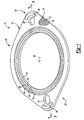
- Figure 1 is a perspective view of an elastomer coated screen gasket according to the principles of the present invention
- Figure 2 is a schematic view of a wire screen used in the gasket of the present invention.
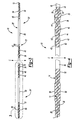
- Figure 3 is a cross sectional view taken along line 3-3 of Figure 1 ;
- Figure 4 is a magnified view of detail 3 in Figure 3 .
- gasket 10 according to the principles of the present invention is shown. It will be understood that the shape and dimensions of the gasket 10 enclosed herein are for illustrative purposes only and do not limit the scope of the present application.
- the gasket 10 includes a screen 12 embedded in an elastomeric material 14.
- the screen 12 (as illustrated in Figure 2 ) includes several openings 16 between the cross weaved wires 17 which facilitate the flow of the elastomeric material 14 therethrough while the gasket 10 is being molded.
- the screen 12 may be comprised of aluminum, copper, steel, carbon fiber, perforated sheeting, such as MYLAR, or any other suitable material and may be pre-cut into a desired shape prior to the introduction of the elastomeric material 14 or may be in sheet form and cut later.
- the screen 12 has a thickness T which according to a first embodiment may be approximately 0.2 millimeters (mm) to 0.3 millimeters (mm). The thickness T is generally uniform.
- a central aperture 18 may be formed along a centerline C prior to the introduction of the elastomeric material 14.
- a first end 20 of the screen 12 may further include a first aperture 22 for receipt of a first coupling mechanism (not shown), such as, for example, a bolt or screw, therethrough.
- the screen 12 has a second end 24 which may include a second aperture 26 for receipt of a second coupling mechanism (not shown).
- the screen 12 has a top side 28 and a bottom side 30 which is coated with the elastomeric material 14.
- the elastomeric material 14 may coat the top side 28 and bottom side 30 of the screen 12 such that the screen 12 is completely embedded by the elastomeric material 14, forming the gasket top side 28' and the gasket bottom side 30', each having a first end 20' and a second end 24'.
- the central aperture 18 of the screen 12 may be coated or remain uncoated by the elastomeric material 14.
- Both the top side 28' and the bottom side 30' may include a plurality of sealing ribs 36, 40, 42.
- the plurality of sealing ribs 36, 40, 42 may be formed from elastomeric material 14 and may surround the central aperture 18 of the screen 12. More specifically, an area 34 having a first predetermined thickness may be formed directly adjacent to the central aperture 18. The area 34 is adjacent a first sealing rib 36.
- the first sealing rib 36 is adjacent a valley 38.
- the valley 38 is further adjacent to a second sealing rib 40.
- the second sealing rib 40 is separated from a third sealing rib 42 by a second valley 44.
- the first sealing rib 36 has a height H1 which is generally greater than a height H2 of the second sealing rib 40.
- the third sealing rib 42 also has a height H3 which is generally smaller than the height H2 of the second sealing rib 40.
- the valleys 38 and 44 are configured such that when a downward force F is applied to the first, second and third sealing ribs 36, 40 and 42, the first, second and third sealing ribs 36, 40 and 42 can deform into the valleys 38 and 44.
- the first, second and third sealing ribs 36, 40, 42 ensure a tight seal.
- the first end 20' of gasket 10 may include a first mounting aperture 46 which corresponds to the first aperture 22 of the screen 12 for receipt of the first coupling mechanism therethrough.
- the first mounting aperture 46 may be configured to extend beyond the first aperture 22 of the screen 12 to provide a first elastomeric buffer region 48.
- the second end 24' of gasket 10 may include a second mounting aperture 50 corresponding to the second aperture 26 of the screen 12 for receipt of the second coupling mechanism therethrough.
- the second mounting aperture 50 may also extend beyond the second aperture 26 of the screen 12 to form a second elastomeric buffer region 52.
- the first and second elastomeric buffer regions 48, 52 ensure a tight seal against the first and second coupling mechanism. It should be understood that the screen 12 may be completely coated with the elastomeric material prior to a cutting process during which the apertures in the screen are formed.
- a first raised portion or shelf 54 may be formed adjacent to the first mounting aperture 46 on both the top side 28' and bottom side 30' of gasket 10.
- a second raised portion or shelf 56 may also be formed on both the top side 28' and bottom side 30' adjacent to the second mounting aperture 50.
- the first raised portion 54 and second raised portion 56 provide a support to prevent the flexing of a part (not shown) which mates with the gasket 10 and thus further ensures a tight seal.
- the elastomeric material 14 may comprise nitrile rubber (NBR) with a low acrylonitrile (ACN) content, medium ACN content NBR, high ACN content NBR, butyl-chlorobutyl, chloroprene, chlorosulfonated polyethylene, ethylene propylene, epichlorohydrin, ethylene vinyl acetate, floursilicone, fluorocarbon, hydrogenated NBR, polyisoprene, polyuacrylate, propylene oxide, polybutadiene, polysulfide, modified NBR, silicone, styrene butadiene rubber (SBR) or any enhanced performance polymer or thermoplastic elastomer.
- NBR nitrile rubber
- ACN acrylonitrile
- the screen 12 is placed into a mold cavity (not shown).
- the screen 12 may be of a predetermined shape or may be in sheet form.
- the elastomeric material 14 is injected into the mold cavity.
- the elastomeric material 14 then flows through the openings 16 in the screen 12 to substantially coat the top and bottom of the screen 12, forming the top side 28' and the bottom side 30' of the gasket 10.
- the mold cavity is such that the elastomeric material 14 flows around the central aperture 18, however, it is envisioned that the central aperture 18 could be created in a later processing step.
- the mold cavity may also be configured to enable the elastomeric material 14 to flow and create the first and second mounting apertures 46, 50 or the first and second mounting apertures 46, 50 may be created in a later processing step.
- the mold cavity may be configured to allow excess elastomeric material 14 to form the first, second and third sealing ribs 36, 40, 42.
- the mold cavity could be designed such that excess elastomeric material 14 may form the first raised portion 54 and the second raised portion 56 adjacent the first and second mounting apertures 46, 50.
- the gasket 10 of the present invention reduces the weight and cost of current gaskets through the use of a screen 12.
- the screen 12 provides the gasket 10 with a compression limiting feature while enabling the gasket 10 to have a reduced thickness.
- the screen 12 also enables the shape of the gasket 10 to be easily modified to suit any desired design change.
- the use of the screen 12 also reduces the amount of torque required to create a sufficient seal.
- the elastomeric material 14 coating the screen 12 is generally more durable, resistant and easier to process than current elastomeric materials used in gaskets.
Landscapes
- Engineering & Computer Science (AREA)
- General Engineering & Computer Science (AREA)
- Mechanical Engineering (AREA)
- Gasket Seals (AREA)
- Sealing Material Composition (AREA)
Claims (5)
- Joint (10) comprenant un treillis (12) en fil métallique ; un matériau élastomère (14) enrobant le treillis (12) en fil métallique, le joint (10) comprenant une première face (28') et une deuxième face (30') et une pluralité de nervures (36, 40, 42) d'étanchéité moulées formées dans au moins une desdites première (28') et deuxième faces (30'), une première nervure (36) d'étanchéité adjacente à et entourant une ouverture (18) du joint (10) ; caractérisé par une deuxième nervure (40) d'étanchéité adjacente à la première nervure (36) d'étanchéité, et une troisième nervure (42) d'étanchéité adjacente à la deuxième nervure (40) d'étanchéité, ladite première nervure (36) d'étanchéité présentant une hauteur supérieure à celle de la deuxième nervure (40) d'étanchéité et la deuxième nervure (40) d'étanchéité présentant une hauteur supérieure à celle de la troisième nervure (42) d'étanchéité.
- Joint selon la revendication 1, le joint comportant en outre au moins un orifice (46, 50) de montage situé entre l'ouverture (18) et un bord (20', 24') dudit joint (10).
- Joint selon la revendication 2, le joint (10) comportant en outre au moins une plage moulée (54, 56) adjacente à l'orifice (46, 50) de montage.
- Joint selon la revendication 1, le matériau élastomère (14) étant un élastomère thermoplastique.
- Joint selon la revendication 1, le matériau élastomère (14) étant choisi dans le groupe formé des : caoutchouc nitrile (NBR) à faible teneur en acrylonitrile (ACN), NBR à teneur moyenne en ACN, NBR à forte teneur en ACN, butyle-chlorobutyle, chloroprène, polyéthylène chlorosulfoné, éthylène-propylène, épichlorhydrine, éthylène acétate de vinyle, fluorosilicone, fluorocarbone, NBR hydrogéné, polyisoprène, polyacrylate, oxyde de propylène, polybutadiène, polysulfure, NBR modifié, silicone et caoutchouc butadiène styrène (SBR).
Applications Claiming Priority (2)
| Application Number | Priority Date | Filing Date | Title |
|---|---|---|---|
| US10/873,845 US20050280214A1 (en) | 2004-06-22 | 2004-06-22 | Elastomer coated screen gasket |
| US873845 | 2004-06-22 |
Publications (2)
| Publication Number | Publication Date |
|---|---|
| EP1610042A1 EP1610042A1 (fr) | 2005-12-28 |
| EP1610042B1 true EP1610042B1 (fr) | 2008-04-23 |
Family
ID=34980119
Family Applications (1)
| Application Number | Title | Priority Date | Filing Date |
|---|---|---|---|
| EP05012074A Expired - Lifetime EP1610042B1 (fr) | 2004-06-22 | 2005-06-04 | Joint plat recouvert d'élastomère |
Country Status (7)
| Country | Link |
|---|---|
| US (1) | US20050280214A1 (fr) |
| EP (1) | EP1610042B1 (fr) |
| JP (1) | JP2006010075A (fr) |
| AT (1) | ATE393337T1 (fr) |
| CA (1) | CA2509889A1 (fr) |
| DE (1) | DE602005006196T2 (fr) |
| MX (1) | MXPA05006777A (fr) |
Families Citing this family (39)
| Publication number | Priority date | Publication date | Assignee | Title |
|---|---|---|---|---|
| US7455300B2 (en) * | 2004-12-30 | 2008-11-25 | Dudman Richard L | Gasket ring with sharp peaks |
| CN101454599B (zh) * | 2006-03-28 | 2015-12-16 | 界面性能材料公司 | 由各种材料形成的垫片 |
| USD536077S1 (en) * | 2006-03-31 | 2007-01-30 | Emerson Network Power, Energy Systems, North America, Inc. | Evaporator shroud for DC cooler |
| USD536078S1 (en) * | 2006-03-31 | 2007-01-30 | Emerson Network Power, Energy Systems, North America, Inc. | Condenser shroud cover for DC cooler |
| USD575381S1 (en) | 2006-03-31 | 2008-08-19 | Emerson Network Power | Condenser shroud for DC cooler |
| USD536079S1 (en) * | 2006-03-31 | 2007-01-30 | Emerson Network Power, Energy Systems, North America, Inc. | Evaporator air mover cover for DC cooler |
| US7862049B2 (en) * | 2006-04-17 | 2011-01-04 | Federal Mogul World Wide, Inc. | Gasket and method of forming a seal therewith |
| WO2008038353A1 (fr) * | 2006-09-27 | 2008-04-03 | Daiki Industries, Co., Ltd. | Joint d'étanchéité |
| US20080280040A1 (en) * | 2007-03-28 | 2008-11-13 | Jeffery Barrall | Gasket Formed From Various Materials And Methods Of Making Same |
| US8579299B2 (en) * | 2009-04-03 | 2013-11-12 | Interface Solutions, Inc. | Gasket having adhesive element |
| GB0922625D0 (en) * | 2009-12-24 | 2010-02-10 | Flexitallic Ltd | A gasket |
| FR2968533B1 (fr) * | 2010-12-08 | 2013-09-06 | Brothier Lab | Dispositif medical de renfort |
| JP5618166B2 (ja) * | 2011-06-09 | 2014-11-05 | Nok株式会社 | ガスケット及びその製造方法 |
| US9702464B1 (en) * | 2011-10-03 | 2017-07-11 | The Patent Well LLC | Non-planar stick gaskets for receipt between a base and a workpiece |
| US8822100B2 (en) * | 2011-11-14 | 2014-09-02 | GM Global Technology Operations LLC | Method of controlling thickness of form-in-place sealing for PEM fuel cell stacks |
| USD714917S1 (en) * | 2012-09-26 | 2014-10-07 | Jody Dale Miller | Waxless urinal gasket |
| US10502321B2 (en) * | 2014-01-14 | 2019-12-10 | Compart Systems Pte, Ltd. | Gasket retainer for surface mount fluid component |
| US9869409B2 (en) | 2013-01-15 | 2018-01-16 | Vistadeltek, Llc | Gasket retainer for surface mount fluid component |
| EP2966321B1 (fr) * | 2013-03-05 | 2019-04-10 | Nok Corporation | Dispositif de réduction de bruit d'aspiration |
| DE102013006777A1 (de) | 2013-04-18 | 2014-10-23 | Samson Aktiengesellschaft | Stellgerät für eine verfahrenstechnische Anlage |
| JP5995775B2 (ja) * | 2013-04-26 | 2016-09-21 | 本田技研工業株式会社 | 樹脂製カバーの取付構造 |
| USD745119S1 (en) * | 2013-11-04 | 2015-12-08 | James Browning | Master flange |
| DE202013010604U1 (de) * | 2013-11-23 | 2014-11-24 | Reinz-Dichtungs-Gmbh | Steuerungssystem |
| DE102014105806A1 (de) | 2014-02-25 | 2015-08-27 | Elringklinger Ag | Verfahren zum Herstellen eines Funktionselements für Flachdichtungen sowie Funktionselement für Flachdichtungen |
| USD759219S1 (en) | 2015-03-11 | 2016-06-14 | Garlock Sealing Technologies, Llc | Gasket having raised sealing surface pattern |
| USD759218S1 (en) | 2015-03-11 | 2016-06-14 | Garlock Sealing Technologies, Llc | Gasket having raised sealing surface pattern |
| USD758728S1 (en) | 2015-03-11 | 2016-06-14 | Garlock Sealing Technologies, Llc | Gasket having raised sealing surface pattern |
| USD778142S1 (en) | 2015-03-11 | 2017-02-07 | Garlock Sealing Technologies, Llc | Gasket having raised sealing surface pattern |
| USD753275S1 (en) | 2015-03-11 | 2016-04-05 | Garlock Sealing Technologies, Llc | Gasket having raised sealing surface pattern |
| USD753274S1 (en) | 2015-03-11 | 2016-04-05 | Garlock Sealing Technologies, Llc | Gasket having raised sealing surface pattern |
| USD777016S1 (en) | 2015-03-11 | 2017-01-24 | Garlock Sealing Technologies, Llc | Gasket having raised sealing surface pattern |
| USD759217S1 (en) | 2015-03-11 | 2016-06-14 | Garlock Sealing Technologies, Llc | Gasket having raised sealing surface pattern |
| US9664284B2 (en) * | 2015-08-05 | 2017-05-30 | General Electric Company | Cover system with gasket system therefor |
| US11280410B2 (en) * | 2015-11-13 | 2022-03-22 | Lgc Us Asset Holdings | Non-metal gasket |
| DE202016100268U1 (de) | 2016-01-21 | 2016-02-25 | Abb Technology Ag | Vorrichtung zur Erzeugung, Übertragung, Verteilung und/oder Verwendung elektrischer Energie oder eine Komponente einer solchen Vorrichtung sowie Gasdichtung für eine solche Vorrichtung oder Komponente |
| CN106499802A (zh) * | 2016-12-19 | 2017-03-15 | 中车长春轨道客车股份有限公司 | 传感器橡胶密封垫及带有该传感器橡胶密封垫的齿轮箱 |
| US11187324B2 (en) * | 2018-06-08 | 2021-11-30 | Lydall Performance Materials (Us), Inc. | Gaskets with a non-compressible core and one or more compressible layers |
| USD921168S1 (en) * | 2019-05-07 | 2021-06-01 | Wehrli Custom Fabrication, Inc. | Flow directing ring |
| USD967355S1 (en) * | 2019-11-19 | 2022-10-18 | Transportation Ip Holdings, Llc | Sealing apparatus with retention ribs for an engine valve cover |
Family Cites Families (19)
| Publication number | Priority date | Publication date | Assignee | Title |
|---|---|---|---|---|
| US1883609A (en) * | 1930-05-31 | 1932-10-18 | William J Dennis | Gasket |
| US3158526A (en) * | 1961-11-20 | 1964-11-24 | Farnam Co F D | Reinforced gasket products |
| US3191950A (en) * | 1962-06-11 | 1965-06-29 | Electrada Corp | Reinforced gasket |
| US3140342A (en) * | 1963-07-05 | 1964-07-07 | Chomerics Inc | Electrical shielding and sealing gasket |
| US3794333A (en) * | 1972-07-20 | 1974-02-26 | Felt Products Mfg Co | Gasket |
| US3936059A (en) * | 1973-10-03 | 1976-02-03 | Federal-Mogul Corporation | Sealing boundary gasket for compression between flanged portions of two mating metal members |
| AU2431077A (en) * | 1976-04-30 | 1978-10-19 | Dowty Seals Ltd | Seals and gaskets |
| US4037009A (en) * | 1976-08-11 | 1977-07-19 | Metex Corporation | Conductive elastomeric elements |
| US4403796A (en) * | 1981-07-27 | 1983-09-13 | Rm Industrial Products Company, Inc. | Expansion joints |
| US4575578A (en) * | 1983-01-05 | 1986-03-11 | Keene Corporation | Radiation shielding and thermally conductive gasket with internal bonding agent |
| US4529257A (en) * | 1983-02-22 | 1985-07-16 | International-Telephone & Telegraph Corp. | Combined electrical shield and environmental seal for electrical connector |
| JPH0414681Y2 (fr) * | 1986-04-11 | 1992-04-02 | ||
| US4955621A (en) * | 1989-09-22 | 1990-09-11 | Jpi Transportation Products, Inc. | Gasket |
| SK28294A3 (en) * | 1991-09-13 | 1995-05-10 | Meillor Sa | Sheet gasket, particular for internal combustion engines |
| US6454276B2 (en) * | 1992-08-19 | 2002-09-24 | The Boeing Company | Corrosion resistant gasket for aircraft |
| GB2327699B (en) * | 1997-07-25 | 2001-09-19 | Draftex Ind Ltd | Sealing strips |
| FR2768211B1 (fr) * | 1997-09-09 | 1999-10-22 | Curty Payen Sa | Joint statique d'etancheite |
| US6460861B1 (en) * | 2001-02-12 | 2002-10-08 | International Truck Intellectual Property Company, L.L.C. | Flexible elongated seal with multiple types of reinforcements |
| US7121556B2 (en) * | 2004-04-07 | 2006-10-17 | Freudenberg-Nok General Partnership | Molded plastic gasket |
-
2004
- 2004-06-22 US US10/873,845 patent/US20050280214A1/en not_active Abandoned
-
2005
- 2005-06-04 EP EP05012074A patent/EP1610042B1/fr not_active Expired - Lifetime
- 2005-06-04 DE DE602005006196T patent/DE602005006196T2/de not_active Expired - Lifetime
- 2005-06-04 AT AT05012074T patent/ATE393337T1/de not_active IP Right Cessation
- 2005-06-14 CA CA002509889A patent/CA2509889A1/fr not_active Abandoned
- 2005-06-21 MX MXPA05006777A patent/MXPA05006777A/es not_active Application Discontinuation
- 2005-06-21 JP JP2005180869A patent/JP2006010075A/ja active Pending
Also Published As
| Publication number | Publication date |
|---|---|
| DE602005006196T2 (de) | 2009-07-09 |
| US20050280214A1 (en) | 2005-12-22 |
| DE602005006196D1 (de) | 2008-06-05 |
| MXPA05006777A (es) | 2006-01-26 |
| ATE393337T1 (de) | 2008-05-15 |
| JP2006010075A (ja) | 2006-01-12 |
| CA2509889A1 (fr) | 2005-12-22 |
| EP1610042A1 (fr) | 2005-12-28 |
Similar Documents
| Publication | Publication Date | Title |
|---|---|---|
| EP1610042B1 (fr) | Joint plat recouvert d'élastomère | |
| US5639103A (en) | Flat gasket, in particular for an internal combustion engine and related manufacturing method | |
| US6089572A (en) | Three-layer gasket with primary and secondary sealing element | |
| US6994354B2 (en) | Vibrationally decoupling gasket | |
| US7213814B2 (en) | Seal assembly | |
| US7121556B2 (en) | Molded plastic gasket | |
| JP6128294B2 (ja) | ウォータージャケットスペーサー | |
| JPWO2020026893A1 (ja) | 密封装置及びガスケット | |
| US20060097458A1 (en) | Gasket assembly | |
| JP2005172225A (ja) | 可撓性ストッパを備えたシーリングガスケット | |
| US20080284112A1 (en) | Gasket having formed load bearing compression limiting features | |
| JP4538238B2 (ja) | ガスケット | |
| EP0688395B2 (fr) | Ameliorations relatives a des joints | |
| CN100353095C (zh) | 平板垫片 | |
| JP4866857B2 (ja) | カバーアセンブリ | |
| US20080226862A1 (en) | Barrier Gasket | |
| EP1629223B1 (fr) | Procede de production d'un joint plat et joint plat | |
| JP4317168B2 (ja) | 気密ガスケット | |
| EP3153747A1 (fr) | Joint intégré à hauteur de compression variable | |
| JP2006029587A (ja) | パッキン | |
| JP3000311U (ja) | シート材およびそれを用いたガスケット | |
| KR100212893B1 (ko) | 라미네이트형 실린더 헤드 가스켓 구조 | |
| JP2001355732A (ja) | 金属ガスケット | |
| JPH0742888U (ja) | ビーターシートガスケット | |
| JPH10331980A (ja) | シリンダヘッドガスケットの製造方法 |
Legal Events
| Date | Code | Title | Description |
|---|---|---|---|
| PUAI | Public reference made under article 153(3) epc to a published international application that has entered the european phase |
Free format text: ORIGINAL CODE: 0009012 |
|
| AK | Designated contracting states |
Kind code of ref document: A1 Designated state(s): AT BE BG CH CY CZ DE DK EE ES FI FR GB GR HU IE IS IT LI LT LU MC NL PL PT RO SE SI SK TR |
|
| AX | Request for extension of the european patent |
Extension state: AL BA HR LV MK YU |
|
| 17P | Request for examination filed |
Effective date: 20060303 |
|
| AKX | Designation fees paid |
Designated state(s): AT BE BG CH CY CZ DE DK EE ES FI FR GB GR HU IE IS IT LI LT LU MC NL PL PT RO SE SI SK TR |
|
| GRAP | Despatch of communication of intention to grant a patent |
Free format text: ORIGINAL CODE: EPIDOSNIGR1 |
|
| GRAS | Grant fee paid |
Free format text: ORIGINAL CODE: EPIDOSNIGR3 |
|
| GRAA | (expected) grant |
Free format text: ORIGINAL CODE: 0009210 |
|
| AK | Designated contracting states |
Kind code of ref document: B1 Designated state(s): AT BE BG CH CY CZ DE DK EE ES FI FR GB GR HU IE IS IT LI LT LU MC NL PL PT RO SE SI SK TR |
|
| REG | Reference to a national code |
Ref country code: GB Ref legal event code: FG4D |
|
| REG | Reference to a national code |
Ref country code: CH Ref legal event code: EP |
|
| REF | Corresponds to: |
Ref document number: 602005006196 Country of ref document: DE Date of ref document: 20080605 Kind code of ref document: P |
|
| REG | Reference to a national code |
Ref country code: IE Ref legal event code: FG4D Free format text: LANGUAGE OF EP DOCUMENT: FRENCH |
|
| PG25 | Lapsed in a contracting state [announced via postgrant information from national office to epo] |
Ref country code: SI Free format text: LAPSE BECAUSE OF FAILURE TO SUBMIT A TRANSLATION OF THE DESCRIPTION OR TO PAY THE FEE WITHIN THE PRESCRIBED TIME-LIMIT Effective date: 20080423 |
|
| NLV1 | Nl: lapsed or annulled due to failure to fulfill the requirements of art. 29p and 29m of the patents act | ||
| PG25 | Lapsed in a contracting state [announced via postgrant information from national office to epo] |
Ref country code: PT Free format text: LAPSE BECAUSE OF FAILURE TO SUBMIT A TRANSLATION OF THE DESCRIPTION OR TO PAY THE FEE WITHIN THE PRESCRIBED TIME-LIMIT Effective date: 20080923 Ref country code: NL Free format text: LAPSE BECAUSE OF FAILURE TO SUBMIT A TRANSLATION OF THE DESCRIPTION OR TO PAY THE FEE WITHIN THE PRESCRIBED TIME-LIMIT Effective date: 20080423 Ref country code: FI Free format text: LAPSE BECAUSE OF FAILURE TO SUBMIT A TRANSLATION OF THE DESCRIPTION OR TO PAY THE FEE WITHIN THE PRESCRIBED TIME-LIMIT Effective date: 20080423 Ref country code: BG Free format text: LAPSE BECAUSE OF FAILURE TO SUBMIT A TRANSLATION OF THE DESCRIPTION OR TO PAY THE FEE WITHIN THE PRESCRIBED TIME-LIMIT Effective date: 20080723 Ref country code: ES Free format text: LAPSE BECAUSE OF FAILURE TO SUBMIT A TRANSLATION OF THE DESCRIPTION OR TO PAY THE FEE WITHIN THE PRESCRIBED TIME-LIMIT Effective date: 20080803 |
|
| PG25 | Lapsed in a contracting state [announced via postgrant information from national office to epo] |
Ref country code: AT Free format text: LAPSE BECAUSE OF FAILURE TO SUBMIT A TRANSLATION OF THE DESCRIPTION OR TO PAY THE FEE WITHIN THE PRESCRIBED TIME-LIMIT Effective date: 20080423 Ref country code: PL Free format text: LAPSE BECAUSE OF FAILURE TO SUBMIT A TRANSLATION OF THE DESCRIPTION OR TO PAY THE FEE WITHIN THE PRESCRIBED TIME-LIMIT Effective date: 20080423 |
|
| PG25 | Lapsed in a contracting state [announced via postgrant information from national office to epo] |
Ref country code: IS Free format text: LAPSE BECAUSE OF FAILURE TO SUBMIT A TRANSLATION OF THE DESCRIPTION OR TO PAY THE FEE WITHIN THE PRESCRIBED TIME-LIMIT Effective date: 20080823 |
|
| ET | Fr: translation filed | ||
| PG25 | Lapsed in a contracting state [announced via postgrant information from national office to epo] |
Ref country code: DK Free format text: LAPSE BECAUSE OF FAILURE TO SUBMIT A TRANSLATION OF THE DESCRIPTION OR TO PAY THE FEE WITHIN THE PRESCRIBED TIME-LIMIT Effective date: 20080423 Ref country code: MC Free format text: LAPSE BECAUSE OF NON-PAYMENT OF DUE FEES Effective date: 20080630 Ref country code: CZ Free format text: LAPSE BECAUSE OF FAILURE TO SUBMIT A TRANSLATION OF THE DESCRIPTION OR TO PAY THE FEE WITHIN THE PRESCRIBED TIME-LIMIT Effective date: 20080423 Ref country code: SE Free format text: LAPSE BECAUSE OF FAILURE TO SUBMIT A TRANSLATION OF THE DESCRIPTION OR TO PAY THE FEE WITHIN THE PRESCRIBED TIME-LIMIT Effective date: 20080723 Ref country code: LT Free format text: LAPSE BECAUSE OF FAILURE TO SUBMIT A TRANSLATION OF THE DESCRIPTION OR TO PAY THE FEE WITHIN THE PRESCRIBED TIME-LIMIT Effective date: 20080423 |
|
| PG25 | Lapsed in a contracting state [announced via postgrant information from national office to epo] |
Ref country code: BE Free format text: LAPSE BECAUSE OF FAILURE TO SUBMIT A TRANSLATION OF THE DESCRIPTION OR TO PAY THE FEE WITHIN THE PRESCRIBED TIME-LIMIT Effective date: 20080423 Ref country code: SK Free format text: LAPSE BECAUSE OF FAILURE TO SUBMIT A TRANSLATION OF THE DESCRIPTION OR TO PAY THE FEE WITHIN THE PRESCRIBED TIME-LIMIT Effective date: 20080423 Ref country code: RO Free format text: LAPSE BECAUSE OF FAILURE TO SUBMIT A TRANSLATION OF THE DESCRIPTION OR TO PAY THE FEE WITHIN THE PRESCRIBED TIME-LIMIT Effective date: 20080423 |
|
| PLBE | No opposition filed within time limit |
Free format text: ORIGINAL CODE: 0009261 |
|
| STAA | Information on the status of an ep patent application or granted ep patent |
Free format text: STATUS: NO OPPOSITION FILED WITHIN TIME LIMIT |
|
| 26N | No opposition filed |
Effective date: 20090126 |
|
| PG25 | Lapsed in a contracting state [announced via postgrant information from national office to epo] |
Ref country code: IE Free format text: LAPSE BECAUSE OF NON-PAYMENT OF DUE FEES Effective date: 20080604 Ref country code: EE Free format text: LAPSE BECAUSE OF FAILURE TO SUBMIT A TRANSLATION OF THE DESCRIPTION OR TO PAY THE FEE WITHIN THE PRESCRIBED TIME-LIMIT Effective date: 20080423 |
|
| PG25 | Lapsed in a contracting state [announced via postgrant information from national office to epo] |
Ref country code: IT Free format text: LAPSE BECAUSE OF FAILURE TO SUBMIT A TRANSLATION OF THE DESCRIPTION OR TO PAY THE FEE WITHIN THE PRESCRIBED TIME-LIMIT Effective date: 20080423 |
|
| REG | Reference to a national code |
Ref country code: CH Ref legal event code: PL |
|
| GBPC | Gb: european patent ceased through non-payment of renewal fee |
Effective date: 20090604 |
|
| PG25 | Lapsed in a contracting state [announced via postgrant information from national office to epo] |
Ref country code: LI Free format text: LAPSE BECAUSE OF NON-PAYMENT OF DUE FEES Effective date: 20090630 Ref country code: CH Free format text: LAPSE BECAUSE OF NON-PAYMENT OF DUE FEES Effective date: 20090630 |
|
| PG25 | Lapsed in a contracting state [announced via postgrant information from national office to epo] |
Ref country code: GB Free format text: LAPSE BECAUSE OF NON-PAYMENT OF DUE FEES Effective date: 20090604 |
|
| PG25 | Lapsed in a contracting state [announced via postgrant information from national office to epo] |
Ref country code: LU Free format text: LAPSE BECAUSE OF NON-PAYMENT OF DUE FEES Effective date: 20080604 Ref country code: HU Free format text: LAPSE BECAUSE OF FAILURE TO SUBMIT A TRANSLATION OF THE DESCRIPTION OR TO PAY THE FEE WITHIN THE PRESCRIBED TIME-LIMIT Effective date: 20081024 Ref country code: CY Free format text: LAPSE BECAUSE OF FAILURE TO SUBMIT A TRANSLATION OF THE DESCRIPTION OR TO PAY THE FEE WITHIN THE PRESCRIBED TIME-LIMIT Effective date: 20080423 |
|
| PG25 | Lapsed in a contracting state [announced via postgrant information from national office to epo] |
Ref country code: TR Free format text: LAPSE BECAUSE OF FAILURE TO SUBMIT A TRANSLATION OF THE DESCRIPTION OR TO PAY THE FEE WITHIN THE PRESCRIBED TIME-LIMIT Effective date: 20080423 |
|
| PG25 | Lapsed in a contracting state [announced via postgrant information from national office to epo] |
Ref country code: GR Free format text: LAPSE BECAUSE OF FAILURE TO SUBMIT A TRANSLATION OF THE DESCRIPTION OR TO PAY THE FEE WITHIN THE PRESCRIBED TIME-LIMIT Effective date: 20080724 |
|
| REG | Reference to a national code |
Ref country code: FR Ref legal event code: PLFP Year of fee payment: 11 |
|
| REG | Reference to a national code |
Ref country code: FR Ref legal event code: PLFP Year of fee payment: 12 |
|
| REG | Reference to a national code |
Ref country code: FR Ref legal event code: PLFP Year of fee payment: 13 |
|
| REG | Reference to a national code |
Ref country code: FR Ref legal event code: PLFP Year of fee payment: 14 |
|
| PGFP | Annual fee paid to national office [announced via postgrant information from national office to epo] |
Ref country code: FR Payment date: 20230623 Year of fee payment: 19 Ref country code: DE Payment date: 20230627 Year of fee payment: 19 |
|
| REG | Reference to a national code |
Ref country code: DE Ref legal event code: R119 Ref document number: 602005006196 Country of ref document: DE |
|
| PG25 | Lapsed in a contracting state [announced via postgrant information from national office to epo] |
Ref country code: DE Free format text: LAPSE BECAUSE OF NON-PAYMENT OF DUE FEES Effective date: 20250101 |
|
| PG25 | Lapsed in a contracting state [announced via postgrant information from national office to epo] |
Ref country code: FR Free format text: LAPSE BECAUSE OF NON-PAYMENT OF DUE FEES Effective date: 20240630 |