EP1610105B1 - Vorrichtung zum Montieren einer elektronischen Modulanordnung in einem Sensor - Google Patents
Vorrichtung zum Montieren einer elektronischen Modulanordnung in einem Sensor Download PDFInfo
- Publication number
- EP1610105B1 EP1610105B1 EP05253795.8A EP05253795A EP1610105B1 EP 1610105 B1 EP1610105 B1 EP 1610105B1 EP 05253795 A EP05253795 A EP 05253795A EP 1610105 B1 EP1610105 B1 EP 1610105B1
- Authority
- EP
- European Patent Office
- Prior art keywords
- weight sensor
- sense
- sensor according
- support member
- side wall
- Prior art date
- Legal status (The legal status is an assumption and is not a legal conclusion. Google has not performed a legal analysis and makes no representation as to the accuracy of the status listed.)
- Ceased
Links
- 238000003466 welding Methods 0.000 description 16
- 238000012546 transfer Methods 0.000 description 11
- 230000003750 conditioning effect Effects 0.000 description 10
- 239000000463 material Substances 0.000 description 10
- 230000007613 environmental effect Effects 0.000 description 9
- 229910001220 stainless steel Inorganic materials 0.000 description 9
- 239000010935 stainless steel Substances 0.000 description 9
- XUIMIQQOPSSXEZ-UHFFFAOYSA-N Silicon Chemical compound [Si] XUIMIQQOPSSXEZ-UHFFFAOYSA-N 0.000 description 6
- 230000003071 parasitic effect Effects 0.000 description 6
- 229910052710 silicon Inorganic materials 0.000 description 6
- 239000010703 silicon Substances 0.000 description 6
- PXHVJJICTQNCMI-UHFFFAOYSA-N Nickel Chemical compound [Ni] PXHVJJICTQNCMI-UHFFFAOYSA-N 0.000 description 4
- 230000000694 effects Effects 0.000 description 4
- 238000005516 engineering process Methods 0.000 description 4
- 239000011521 glass Substances 0.000 description 4
- 230000004048 modification Effects 0.000 description 4
- 238000012986 modification Methods 0.000 description 4
- 229910021421 monocrystalline silicon Inorganic materials 0.000 description 4
- 239000004593 Epoxy Substances 0.000 description 3
- 238000000034 method Methods 0.000 description 3
- 230000035945 sensitivity Effects 0.000 description 3
- RYGMFSIKBFXOCR-UHFFFAOYSA-N Copper Chemical compound [Cu] RYGMFSIKBFXOCR-UHFFFAOYSA-N 0.000 description 2
- BQCADISMDOOEFD-UHFFFAOYSA-N Silver Chemical compound [Ag] BQCADISMDOOEFD-UHFFFAOYSA-N 0.000 description 2
- 238000005452 bending Methods 0.000 description 2
- 239000003990 capacitor Substances 0.000 description 2
- 229910052802 copper Inorganic materials 0.000 description 2
- 239000010949 copper Substances 0.000 description 2
- 239000008393 encapsulating agent Substances 0.000 description 2
- 239000007788 liquid Substances 0.000 description 2
- 230000014759 maintenance of location Effects 0.000 description 2
- 239000002184 metal Substances 0.000 description 2
- 229910052751 metal Inorganic materials 0.000 description 2
- 229910052759 nickel Inorganic materials 0.000 description 2
- 238000004806 packaging method and process Methods 0.000 description 2
- 230000008569 process Effects 0.000 description 2
- 230000002441 reversible effect Effects 0.000 description 2
- 229910052709 silver Inorganic materials 0.000 description 2
- 239000004332 silver Substances 0.000 description 2
- 230000002411 adverse Effects 0.000 description 1
- 230000015572 biosynthetic process Effects 0.000 description 1
- 230000008859 change Effects 0.000 description 1
- 230000002860 competitive effect Effects 0.000 description 1
- 230000007797 corrosion Effects 0.000 description 1
- 238000005260 corrosion Methods 0.000 description 1
- 239000013078 crystal Substances 0.000 description 1
- 229910021419 crystalline silicon Inorganic materials 0.000 description 1
- 230000007423 decrease Effects 0.000 description 1
- 230000003247 decreasing effect Effects 0.000 description 1
- 238000011161 development Methods 0.000 description 1
- 238000010586 diagram Methods 0.000 description 1
- 230000002708 enhancing effect Effects 0.000 description 1
- 239000011888 foil Substances 0.000 description 1
- 230000006872 improvement Effects 0.000 description 1
- 238000010348 incorporation Methods 0.000 description 1
- 230000005923 long-lasting effect Effects 0.000 description 1
- 230000007257 malfunction Effects 0.000 description 1
- 238000004519 manufacturing process Methods 0.000 description 1
- 230000013011 mating Effects 0.000 description 1
- 230000007246 mechanism Effects 0.000 description 1
- 239000007769 metal material Substances 0.000 description 1
- 230000002093 peripheral effect Effects 0.000 description 1
- 229920001296 polysiloxane Polymers 0.000 description 1
- 230000002829 reductive effect Effects 0.000 description 1
- 230000004044 response Effects 0.000 description 1
- 238000004092 self-diagnosis Methods 0.000 description 1
- 230000007704 transition Effects 0.000 description 1
- 238000005303 weighing Methods 0.000 description 1
Images





Classifications
-
- G—PHYSICS
- G01—MEASURING; TESTING
- G01G—WEIGHING
- G01G19/00—Weighing apparatus or methods adapted for special purposes not provided for in the preceding groups
- G01G19/40—Weighing apparatus or methods adapted for special purposes not provided for in the preceding groups with provisions for indicating, recording, or computing price or other quantities dependent on the weight
- G01G19/413—Weighing apparatus or methods adapted for special purposes not provided for in the preceding groups with provisions for indicating, recording, or computing price or other quantities dependent on the weight using electromechanical or electronic computing means
- G01G19/414—Weighing apparatus or methods adapted for special purposes not provided for in the preceding groups with provisions for indicating, recording, or computing price or other quantities dependent on the weight using electromechanical or electronic computing means using electronic computing means only
- G01G19/4142—Weighing apparatus or methods adapted for special purposes not provided for in the preceding groups with provisions for indicating, recording, or computing price or other quantities dependent on the weight using electromechanical or electronic computing means using electronic computing means only for controlling activation of safety devices, e.g. airbag systems
-
- B—PERFORMING OPERATIONS; TRANSPORTING
- B60—VEHICLES IN GENERAL
- B60R—VEHICLES, VEHICLE FITTINGS, OR VEHICLE PARTS, NOT OTHERWISE PROVIDED FOR
- B60R21/00—Arrangements or fittings on vehicles for protecting or preventing injuries to occupants or pedestrians in case of accidents or other traffic risks
- B60R21/01—Electrical circuits for triggering passive safety arrangements, e.g. airbags, safety belt tighteners, in case of vehicle accidents or impending vehicle accidents
- B60R21/015—Electrical circuits for triggering passive safety arrangements, e.g. airbags, safety belt tighteners, in case of vehicle accidents or impending vehicle accidents including means for detecting the presence or position of passengers, passenger seats or child seats, and the related safety parameters therefor, e.g. speed or timing of airbag inflation in relation to occupant position or seat belt use
- B60R21/01512—Passenger detection systems
- B60R21/01516—Passenger detection systems using force or pressure sensing means
Definitions
- This invention relates generally to condition responsive sensors and more particularly to weight sensors used for weighing occupants of a vehicular seat in order to prevent or modify airbag deployment for improved safety of the seat occupant.
- US 6 224 094 discloses a vehicle occupant weight sensor comprising opposing studs one having a T-shape and the other a cup shape, which when subjected to the weight of the occupant compresses a liquid therebetween.
- a silicon micromachine sensor measures the pressure of the liquid and hence the weight applied and passes a signal of that along wires passing out of the sensor along the axis of the cup-shaped stud.
- US 2003/0213623 discloses a load cell comprising a disc spring having load measuring devices thereon.
- a housing has a flange contacting the periphery of the disc spring.
- the disc is also loaded at its centre by a ball bearing mounted on a slider mounted on the thrust surface of a piston.
- the housing also mounts an electronic circuit.
- An object of the present invention is the provision of weight sensor apparatus having sense elements with high sensitivity, good stability, good environmental resistance, strong overstress capability and good rejection of parasitic loads.
- Another object of the invention is the provision of a vehicular seat occupant weight sensor apparatus for measuring an occupant's weight by sensing the force transmitted to the vehicle floor from the seat.
- Yet another object of the invention is the provision of a seat weight sensor having an output signal that is proportional to seat weight, that is accurate from -40 degrees C to 115 degrees C, that has minimal vertical height and that is stable over time and during overload exposures (for example, as a result of accidents).
- Still another object of the invention is the provision of such a sensor which will not compromise the mechanical integrity of existing seat assembly architectures during overload exposures (e.g., accidents) as well as the provision of packaging and means of attachment which permit easy incorporation into the vehicle assembly during a high volume production.
- Another object of the invention is the provision of apparatus for mounting an electronic module assembly in a sensor in close, rigid proximity with a stress sensitive sense surface without introducing any unnecessary stresses to the surface, particularly those which can vary over time.
- an occupant weight sensor for a vehicular seat made in accordance with the invention is adapted for interposition between a first frame fixedly attached to the chassis of a vehicle and the seat, for example, a second frame which supports the seat and comprises a sense element having a first body with a generally flat surface having an outer periphery and with piezoresistors attached to the surface and electrically connected in a full Wheatstone configuration.
- a post extends outwardly from the first body along a first longitudinal axis for attachment to the first frame.
- a second body is formed with a force transfer portion permanently attached to the first body along the outer periphery thereof and has a mounting portion for attachment to the second frame.
- Conditioning electronics and a connector are provided for conditioning the bridge output signal and providing electrical power and output.
- the piezoresistors are disposed on the sense surface at selected locations to minimize affects of parasitic loads.
- the full bridge comprises first and second half bridges wherein the first half bridge has a first piezoresistor disposed adjacent to the outer periphery of the first body at one end of a common diameter and a second piezoresistor disposed adjacent to the center of the circular sense surface and the second half bridge has a third piezoresistor disposed adjacent to the center of the sense surface and a fourth piezoresistor disposed adjacent to the outer periphery of the sense surface at the opposite end of the common diameter.
- the full bridge comprises first and second half bridges wherein the first half bridge has a first piezoresistor aligned radially adjacent to the outer periphery of the sense element along a common diameter on one side of the center of the circular surface and a second piezoresistor aligned tangentially disposed closely adjacent to the first piezoresistor, and the second half bridge has third and fourth piezoresistors similarly disposed on the sense surface diametrically opposed to the first and second piezoresistors.
- the piezoresistors are composed of monocrystalline silicon which are glass bonded to the sense surface to provide strong signal to noise ratios and high levels of mechanical safety factor. If desired, the piezoresistors of one or more half bridges may be formed on the same piece of silicon.
- the sense element comprises a first generally cylindrical body having a first longitudinal axis and a portion formed with a circular flat sense surface lying in a plane generally perpendicular to the first longitudinal axis.
- the body has an outer periphery circumscribing the sense surface.
- a plurality of strain gauges are disposed on the sense surface and a post extends outwardly from the body along the first longitudinal axis.
- a second body is attached to the outer periphery of the first body and has a second longitudinal axis generally coincident with the first longitudinal axis when the two bodies are attached to one another and a second post extends outwardly from the second body along the second longitudinal axis.
- An annular axial load applying surface is formed on the second body circumscribing the second post and an annular load reacting surface is formed on and circumscribes the first post and a circumferential groove is formed in the outer surface of the first body forming a web extending between the outer periphery of the first body and the first post to mitigate the affects of parasitic loads applied to the sensor.
- the web is formed with a selected length which is greater than the width of the web.
- a metallic cup-shaped support ring having an end wall and a side wall depending therefrom is rigidly attached to the first body by laser welding the distal free end of the support ring side wall to a seat on the first body removed from the sense surface but with the end wall extending over the planar sense surface.
- a control gap is provided between the end wall and the sense surface and between the side wall and the first body except for the distal free end.
- An electronic module assembly is suitably attached mechanically and electrically to the opposite face surface of the end wall of the support ring by suitable means such as electrically conductive epoxy or laser welding to a ground trace of a printed circuit board of the electronic module assembly.
- Occupant weight sensors made in accordance with the invention employ monocrystalline silicon strain gauge technology to convert mechanical inputs from the system, i.e., the weight of the occupant of the seat into electrical signals.
- monocrystalline silicon strain gauge technology to convert mechanical inputs from the system, i.e., the weight of the occupant of the seat into electrical signals.
- Such technology used for various automotive pressure sensing applications is known, as shown and described in U.S. Patent No. 6,453,747 , assigned to the assignee of the present invention.
- the piezoresistors are electrically connected to form a full Wheatstone bridge.
- the bridge provides a differential output voltage which is proportional to the applied mechanical input, i.e., occupant weight.
- This signal is calibrated and compensated with a bridge conditioning ASIC to ultimately provide the system with a signal proportional to the externally applied weight.
- the ASIC provides full conditioning of the sensor output over the entire operating range of force and temperature. While it is preferred that the output is supply-ratiometric analog, other output formats could be used if desired, such as PWM (pulse width modulation) or low level bus.
- PWM pulse width modulation
- low level bus In addition to providing a force signal, an option could be included to provide a temperature signal to the system.
- a temperature signal could be provided on a continuous basis on an extra connector pin or it could be time multiplexed into the force signal pin.
- the conditioning electronics can also be provided with self-diagnosis for informing the control system when certain malfunctions are present in the sensor output or in the electrical connection between the sensor and the system as taught in copending application Serial No. 09/952,257 , Publication No. US-2002-0033700-A1 , assigned to the assignee of the present invention.
- occupant weight sensor 1 made in accordance with the invention includes a sense element 2, an electronic module or circuit assembly 3, a bridge conditioning ASIC 4, a sensor package 5 and a connector 6.
- Sense element 2 comprises piezoresistors R1, R2, R3 and R4 electrically connected to form a full Wheatstone bridge and with piezoresistors R1, R4 decreasing in resistance and piezoresistors R2 and R3 increasing in resistance with increasing load.
- the bridge is electrically connected to bridge conditioning ASIC 4 with bridge voltage pin V BRG of ASIC 4 connected to the junction of piezoresistors R1, R3, input pins V INM and V INP of ASIC 4 connected to the junction of piezoresistors R3, R4 and R2, R1, respectively.
- circuit assembly 3 also includes several suitable filter capacitors.
- Fig. 1 a shows one possible position of an occupant weight sensor when mounted for use in a vehicle.
- An occupant weight sensor 32 is shown made according to one of the preferred embodiments to be described below interposed between a first, broken away, frame 7 for fixed attachment to the chassis of a vehicle and a second, broken away, seat support frame 8. It will be understood that the sensor could also be mounted in other locations, such as above seat tracks, i.e., between an upper track and a pan frame.
- Figs. 2 and 3 show an occupant weight sensor 10 made according to a first preferred embodiment which incorporates functional components of Fig. 1 .
- Sensor 10 comprises a sense element, best seen in Figs. 3, 3a , formed of a unitary body 12 of suitable material, such as stainless steel, having a high yield point, good corrosion resistance and being compatible with the strain gauge attachment process, to be described.
- the body is formed with suitable means at one end to mechanically fasten the sense element to a suitable structure.
- a threaded post 12a having a longitudinal axis 12b is shown.
- a longitudinally extending orientation flat 12c is formed along the threaded post.
- a generally planar sense surface 12d is disposed essentially normal to longitudinal axis 12b.
- sense surface 12d is circular in shape.
- the body also has a radial flange 12e extending outwardly beyond the sense surface forming an outer periphery to serve as a mechanical interface with a second body to be described.
- Strain gauges comprising piezoresistors R1-R4 are fabricated from single crystal silicon and, as noted supra, provide a gauge factor of approximately 150.
- a glass bonding process known in the industry, is used to permanently attach the gauges to sense surface 12d by means of glass 12f, as best seen in Fig. 3b , providing high sensitivity, good stability, good environmental resistance and strong overstress stability.
- an occupant weight sensor measures only the axial load applied to the sensor in a manner to be described below so that the weight of the occupant can be inferred.
- forces are applied to the sense element outside of a "pure" axial force. These loads, frequently termed parasitic loads, shift the sensor offset and compromise the determination of the occupant weight.
- piezoresistors are all disposed along a common diameter 12g of the circular sense surface with piezoresistors R1 and R4 closely adjacent to the outer periphery 12h on opposite sides of center and with piezoresistors R2, R3 closely adjacent to the center on opposite sides thereof.
- Sense element body 12 may be provided with a hub portion 12k on threaded post 12a providing a surface 12m as a load reacting surface.
- An annular groove 12n shown in Fig. 3a but not shown in Figs. 2b, 2c , may be formed between hub 12k and radial flange 12e to tailor the strain field in the area of the gauges.
- a second body 14 formed of suitable material, such as stainless steel, which is provided with a centrally disposed opening 14e to receive sense element body 12 with radial flange 12e permanently attached to second body 14 as by laser welding about the outer periphery of the flange.
- Second body 14 comprises an elongated plate like element 14a having first and second ends with a mounting hole 14b disposed adjacent each end for attachment to suitable structure so that the sensor is interposed between support structure for the vehicle seat and the chassis of the vehicle.
- the portion of element 14a welded to radial flange 12e serves as a force transfer portion for the sense element 12.
- Second body 14 also mounts a circuit board (not shown) to which the strain gauges are wire bonded.
- the board includes electronics for compensating the sense element output to achieve accurate output across a full temperature range.
- the electronics are sealed from the environment by an environmental cover 14c and a mating environmental seal (not shown).
- An electrical connector 14d provides a means for externally powering the sensor and receiving the sensor output.
- a second preferred embodiment of the invention shows an occupant weight sensor 20 comprising a sense element having a first body 22 similar to body 12 shown in Figs. 3, 3a and formed with a generally planar circular sense surface 22a and having an outer periphery 22b thereabout in the form of an outwardly radially extending flange forming a stepped seating surface 22m axially spaced from the sense surface.
- Threaded post 22c extends in a first direction away from hub 22d of body 22 along a longitudinal axis 22e and preferably includes an orientation flat 22f. Longitudinal axis 22e is essentially normal to planar sense surface 20a and passes through the center of the circular sense surface.
- annular groove 22g is formed between body 22 of the sense element and threaded post 22c. Additionally, an annular groove 22h is formed in the exterior surface of body 22 between the post and the stepped seating surface 22m to tailor the strain field in the area of the gauges by flattening the strain field in that area. This will be described in greater detail below in connection with Fig. 8a .
- a second body 24 comprises an end wall 24a formed with a tubular sidewall 24b to form a recess 24c.
- a second threaded post 24d extends away from end wall 24a along a longitudinal axis 24e. Threaded post 24d preferably is provided with an orientation flat 24f similar to flat 22f of the first body.
- the outer distal portion 24g of tubular wall 24b is received on stepped seat 22m, preferably spaced slightly from sense surface 22a and is permanently attached thereto around the periphery, as by welding.
- an annular load application surface 24h is formed on second body 24 about post 24d.
- Loads applied to post 24d and surface 24h are transferred to the sense element through the outer distal portion 24g which serves as a force transfer portion.
- the longitudinal axes 22e, 24e are essentially coincident passing through the center of the circular sense surface 22a.
- Second body 24 is formed with an opening 24k in sidewall 24b to provide access for laterally extending connector 24m formed of suitable electrically insulative material attached to second body 24 along with strain relief cap 24n by suitable fasteners 24o.
- Wire leads 24p extend through the connector and strain relief cap and are connected to electronics (not shown) on circuit board 22o received in recess 24c.
- An output conditioning ASIC 22p is mounted on the circuit board and suitable piezoresistors are wire bonded to the circuit board, electrically connected to form a Wheatstone bridge.
- Figs. 5, 5a-5c show a third preferred embodiment of an occupant weight sensor made in accordance with the invention.
- Sensor 26 comprises a sense element similar to the sense elements of the previous embodiments with a circular planar sense surface 28a on which is mounted suitable piezoresistors electrically connected in the form of a Wheatstone bridge, a radially outwardly extending flange preferably longitudinally offset from the sense surface forming a seat 28b for receipt of the tubular force transfer portion of a second body to be discussed.
- a threaded post 28c extends outwardly from body 28 along the longitudinal axis which is essentially normal to the circular sense surface and which passes through the center thereof.
- a hub portion of the fixed end of the post forms an annular force transfer portion 28d and an annular groove 28e is formed in the exterior surface of body 28 intermediate to the post and seat 28b.
- Second body 30 is formed with an externally threaded portion 30a formed with a longitudinally extending opening 30b through the body. Portion 30a is joined to tubular sidewall 30c having a distal end portion 30d, which serves as the force transfer portion, received on seat 28b of the first body member and permanently attached thereto as by welding. Sidewall 30c is preferably formed with an external polygonal, e.g., hexagonal, configuration to facilitate handling and mounting and internally defines an electronics receiving recess 30e. The external transition between wall portions 30a and 30c form an annular force application surface for applying a load to the sense element through annular seat 28b.
- An electrical connector 30f formed of suitable electrically insulative material is received in opening 30b and mounts axially extending wire leads (not shown but received in holes 30g extending longitudinally through the connector).
- An environmental seal 30h is disposed between the connector and the wall of portion 30a defining opening 30b.
- a circuit board 28f with a signal conditioning ASIC is received in recess 30e and, as in the previous embodiments described above, electrical connections are made between piezoresistors mounted on sense surface 28a (not shown) exposed through openings 28g formed in the circuit board.
- FIG. 6 and 6a-6g A fourth preferred embodiment of an occupant weight sensor is shown in Figs. 6 and 6a-6g as well as Fig. 1 a.
- Sensor 32 of this embodiment comprises a sense element having a first body 34 composed of suitable material such as stainless steel, see Figs. 6b, 6c in particular, having a circular, planar sense surface 34a and having an outer periphery 34b preferably longitudinally offset from the sense surface to form an annular seat 34c.
- a second intermediate annular flange 34d is formed between seat 34c and sense surface 34a to facilitate assembly of other components to be discussed.
- a threaded post 34e extends away from body 34a along longitudinal axis 34f.
- a suitable orientation flat 34g may be formed on threaded post 34e or, as shown, on the outer periphery 34b.
- Post 34e is formed with a hub portion having a portion 34k of increasing diameter with increasing distance from body 34 and having a lower radially inwardly extending surface 34m which serves as a force reacting surface.
- An annular groove 34n is formed in the exterior surface of the body intermediate to the post and annular seat 34c. This groove serves to flatten the strain field on sense surface 34a in the region of piezoresistor placement near the outer periphery of the sense surface.
- Single crystalline silicon piezoresistors or gauges are glass bonded to the sense surface as described above and electrically connected to form a full Wheatstone bridge and are disposed so that for each half bridge, one gauge increases resistance with increasing load and the other gauge decreases resistance with increasing load.
- one gauge is aligned radially near the perimeter of the sense surface and the second gauge is aligned tangentially closely to the first gauge.
- piezoresistors placed close to one another can comprise either individual pieces of silicon or they can be formed on the same silicon crystal.
- the differential output of a full bridge is less sensitive to an applied couple. Further improvement can be obtained by tailoring the configuration of the sense element to flatten the strain field in the area of the gauges, as will be discussed further, below.
- sensor 32 in addition to sense element body 34, sensor 32 includes a second body 36, a circuit board 38, a weld ring 40, a contact holder 42, contact springs 44, and an environmental seal 46.
- Circuit board 38 is disposed on sense surface 34a with cut-out portions 38a aligned with the piezoresistors bonded to the sense surface.
- a plurality of radially outwardly extending tabs 38b are received in slots 40a of weld ring 40, see Fig. 6d .
- the weld ring is slidingly received on annular flange 34d with folded over retainer tabs 40b engaging the top surface of circuit board 38.
- a generally disc shaped contact spring holder 42 having a plurality of through holes 42a respectively mount therein suitable contact coil springs 44.
- Weld ring 40 is formed with upwardly extending flanges 40c having a retention feature for receipt in complimentary retention features on the perimeter of the contact holder.
- Environmental seal 46 in the form of an O-ring is received on top of spring holder 42 with contact springs 44 engaging selected conductive pads on the circuit board on one end with the other end extending above the surface of the contact holder.
- Second body 36 is formed of suitable material such as stainless steel and has an end wall 36a and a tubular sidewall 36b defining a recess 36c.
- a threaded post 36d which may be provided with an orientation flat 36f, extends outwardly from the body along a longitudinal axis 36e.
- An opening 36g is formed in sidewall 36b to allow placement of an insert molded connector/ terminal assembly 36h, as seen in Fig. 6f , received through the opening and seated in recess 36c.
- Assembly 36h includes a plurality of terminals 36k, the terminals each having a conductive pad 36m exposed through a cut away portion of the connector/terminal assembly, as shown in Fig.
- Second body 36 is received on first body 34 with the free end portion (force transfer portion) of tubular wall 36b received on seat 34c and attached thereto around the periphery as by laser welding.
- the longitudinal axes 34f and 36e essentially coincide and contact springs 44 engage conductive pads 36m of the connector/terminal assembly.
- an electrically insulative shroud 36n is received over terminals 36k and is attached to the connector, terminal assembly as by being ultrasonically welded thereto.
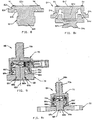
- Figs. 7, 7a-7c show modifications of the Fig. 6 sensor.
- Sensor 48 comprises a sense element having a first body 50 composed of suitable material, such as stainless steel, having a circular, planar sense surface, as in the Fig. 6 embodiment, and having an outer periphery 50a forming an annular seat for receiving the force transfer portion or distal free end 52a of the tubular sidewall of second body 52.
- a threaded post 52b extends away from second body 52 along a longitudinal axis which is coincident with longitudinal axis 50c of body 50 passing through the center of the sense surface once the bodies are joined together as by laser welding around the outer periphery as indicated at 53.
- a post 50b also extends away from body 50 along longitudinal axis 50c and is fixedly attached preferably to a central portion of an elongated bracket 54, as by welding thereto.
- Bracket 54 is formed with a mounting hole 54a adjacent to each opposite end of the elongated bracket for attachment to the first frame connected to the chassis of a vehicle.
- First body 50 is formed with an annular recess 50d in the outer surface of the body between post 50b and the outer periphery 50a, to be discussed below in relation to Figs. 8, 8a .
- a snap ring 56 having a locking feature in the form of an inwardly extending protrusion 56a formed on the inside surface thereof is received on first body 50 with the ring circumscribing the sense surface.
- Protrusion 56a is received in a recess 50e formed in a cylindrical sidewall portion of first body 50 defining the sense surface.
- Ring 56 may be formed with an orientation feature, such as longitudinally extending rib 56b received in a matching groove formed in the cylindrical wall portion.
- Ring 56 is generally cylindrical and, when seated on first body 50, extends above the sense surface and provides a mounting seat for contact spring holder 58 as well as forming a housing for silicone gel placed around the wire bonds connected to the ASIC.
- a suitable connector assembly 60 mounts pin terminals 60a which provides electrical connection to circuit board 50f through contact springs 44 as in the Fig. 6 sensor.
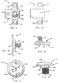
- Fig. 8 shows a sense element 62, with its post 62a broken away, similar to those described in the preceding preferred embodiments, particularly the embodiment shown in Fig. 6b , while sense element 64 in Fig. 8a shows a sense element similar to that of sensor 48 of Fig. 7 but having a threaded post 64a rather than bracket 54.
- Post 64a is broken away for purposes of illustration.
- annular groove 62b is formed in body 62 through the exterior surface between post 62a and annular seat 62c for seating the force transfer portion of a second body (not shown) received on and attached to the outer periphery of the body 62 for applying occupant load to the sensor.
- Groove 62b in effect forms an annular web 62e having a selected width between the groove and seat 62c and a selected length depending on the depth of the groove. The formation of this web serves to flatten the strain field on the outer circumferential portion of sense surface 62d.
- Sense element 64 of Fig. 8a comprises first and second body portions 64a, 64c of suitable metallic material, such as stainless steel, welded together to form a unitary sense element formed with an annular recess or groove 64d, generally U-shaped in cross section at each side of the cross sectional view.
- the groove effectively is formed between the post and annular seat 64e and defines a web 64g between annular seat 64e and sense surface 64f which has a selected length greater than the selected width of the web.
- the ratio of a selected web length greater than the selected web width provides an enhanced flattening effect of the strain field in the outer peripheral portion of sense surface 64f.
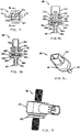
- Figs. 9 and 9a show a sensor similar to the Fig. 7 sensor but having a modified sense element.
- Sensor 66 comprises a sense element having a first body 68 composed of suitable material, such as stainless steel, having a circular planar sense surface as in the Fig. 7 embodiment, and having an outer periphery 68a forming an annular seat for receiving the force transfer portion or distal free end 70a of the tubular sidewall of second body 70.
- a threaded post 70b extends away from second body 70 along a longitudinal axis which is coincident with longitudinal axis 68c of body 68 passing through the center of the sense surface once the bodies are joined together as by laser welding around the outer periphery.
- a post 68b also extends away from body 68 along longitudinal axis 68c and extends through a bore 68d formed through a bracket 72 and is fixedly attached to the bracket as by welding thereto at 68g on the lower side of the bracket. Any suitable welding procedure may be used such as CO 2 laser welding.
- axial loading results in the weld between post 50b and bracket 54 being placed in tension. As the bracket bends in high load conditions, since the bracket is held through mounting holes 54a, the spin weld is put in bending. High stresses are at the edge of the weld which can cause the weld to unzip.
- a more robust sense element is provided by inserting the post in bore 68d of bracket 72.
- weld 68g is placed in shear, even during bending of the bracket, with the load distributed across the full weld area.
- annular recess 68e is formed in the outside surface of first body 68 between post 68b and the outer periphery 68a forming web 68f having a selected length greater than the selected width of the web.
- the description of the Fig. 7 embodiment can be referred to for details of the remaining structure.
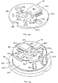
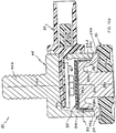
- sensor 80 comprises a mounting bracket or flange 82, a sense element or first body 84, a support ring 86, an electronic module 88, contact springs 90, a contact spring holder 92, a second body 94, an environmental seal 96 and a connector/shroud 98 which dove-tails into an opening in the tubular side wall of second body 94.
- first body 84 composed of suitable material such as stainless steel, has a generally circular, planar sense surface 84a and an outer periphery 84b, preferably offset longitudinally from the sense surface, to form a radially extending annular seat 84c for receiving the force transfer portion or distal end 94a of the tubular side wall of second body 94.
- a second intermediate radially extending annular seat 84d is formed between annular seat 84c and the sense surface 84a for receiving support ring 86, to be discussed.
- First body 84 is also preferably formed with an annular recess 84e in the outside surface between a post 84g extending away from first body 84 along longitudinal axis 84h and the outer periphery 84b forming web 84f having a selected length greater than the selected width of the web, as in the Fig. 7 sensor.
- Post 84g is received in bore 82a of an elongated bracket 82 having a mounting hole at two opposite ends (not shown but similar to mounting holes 54a of bracket 54 in Fig. 7c ) for attachment to seat structure.
- Post 84g is fixedly attached to bracket 82, preferably by laser welding.
- Support ring 86 is a formed of suitable material, such as stainless steel and is generally cup-shaped having a circular end wall 86a and a depending side wall 86b. Three bend tabs 86c extend upwardly beyond end wall 86a to provide orientation features for a printed circuit board 88a, to be discussed. It will be understood that the particular number of tabs provided is a matter of choice.
- a plurality of cantilever springs 86d are formed in side wall 86b and extend outwardly. Four springs are used in the described embodiment but again, the number of springs employed is a matter of choice.
- a concave surface area 86e may be formed in end wall 86a and side wall 86b that interfits with a corresponding notch in first body 84 and serves as an alignment feature for the support ring relative to the first body.
- End wall 86a is also formed with cut-out openings 86f for alignment with strain gauges on sense surface 84a of the type discussed above, for example, in relation to the Fig. 6 sensor.
- An opening 86g may also be formed in end wall 86a at a location corresponding to the position of an ASIC mounted on printed circuit board 88a of the electronic module assembly 88, discussed below.
- the end wall 86a can be formed with upwardly extending areas or convex features to control spacing of the printed circuit board, to be discussed, and the support ring, if desired.
- Support ring 86 is received on first body 84 with the distal free end 86h supported on radially extending annular seat 84d and is permanently attached thereto, preferably by laser welding at selected locations around the periphery, such as four spaced apart locations.
- the number of welds employed is a matter of choice and, if desired, could be a continuous weld around the periphery.
- Side wall 86b, as well as end wall 86a are spaced from the first body sufficiently to provide a control gap to ensure that the only contact between support ring 86 and first body 84 is at the distal free end 86h of the support ring side wall 86b, well removed from the location of the strain gauges on sense surface 84a.
- Electronic module assembly 88 comprises a double sided copper and nickel plated printed circuit board 88a on which are disposed signal conditioning ASIC 88b, various related passive components, including, but not limited to capacitors and resistors, spring contact pads 88c and gauge contact pads 88d.
- Printed circuit board 88 is configured to correspond to end wall 86a of the support ring and is received thereon. The board is provided with tab 86c receiving recesses 88e spaced along the outer periphery of the board and notch 88f to provide alignment with the support ring. Openings 88g are formed through the printed circuit and are aligned with and generally match openings 86g of the support ring when the electronic module assembly is received on end wall 86a, see Fig. 10c .
- the electronic module assembly needs to be rigidly attached to the sense element, i.e., the first body, to ensure a robust electrical connection between the assembly and the silicon gauges, however, stress applied to the sense surface due to the attachment needs to be minimized for reliable, long lasting and accurate performance.
- Mounting of the support ring on first body 84 so that attachment forces caused by mounting the electronic module assembly on end wall 86a are isolated from the sense surface in accordance with the invention has the result that the particular means used for attaching the assembly to the end wall is not critical.
- the printed circuit board 88a is mechanically and electrically connected to support ring 86 by suitable means such as by using silver epoxy or by laser welding a nickel plated copper ground trace (not shown) on the reverse side of board 88a.
- the grounding path of the metal components of the sensor includes the ground trace, support ring 86, the weld connection between the support ring and first body 84 and between bodies 84 and 94 and a weld connection 98b with a pin of connector/shroud 98 ( Fig. 10d ).
- Second body 94 as in the Figs. 6 and 7 sensors, is provided with a second threaded post 94b and tubular side wall 94c formed with an opening 94d for dove-tail receipt of connector 98 and environmental seal 96.
- Distal end 94a of the tubular side wall is received on annular seat 84c of first body 84 and welded thereto as described in the previous embodiments with the longitudinal axis 94h essentially coinciding with axis 84h forming a common axis.
- Springs 90 are held in spring holder 92 which is suitably attached to connector 98, as by interference snap pins 92a ( Fig. 10 ) or ultrasonic weld joints.
- the springs make electrical contact, providing a suitable contact force, between spring contact pads 88c on printed circuit board 88a and connector pins, such as pin 98a shown in Fig. 10d .
- a force sensor is shown and described as the particular sensor in the embodiment described, it is within the purview of the invention to use other types of sensors having a stress sensitive sense surface with the support ring of the Figs. 10 , 10a-10d embodiment, for example, a pressure sensor such as that shown and described in U.S. Patent No. 6,453,747 , referenced above.
Landscapes
- Engineering & Computer Science (AREA)
- Physics & Mathematics (AREA)
- Mathematical Physics (AREA)
- Theoretical Computer Science (AREA)
- Mechanical Engineering (AREA)
- General Physics & Mathematics (AREA)
- Measurement Of Force In General (AREA)
- Force Measurement Appropriate To Specific Purposes (AREA)
Claims (13)
- Gewichtssensor (32, 10, 20, 26, 48, 66, 80), mit:einem ersten, allgemein zylindrischen Körper (12, 22, 28, 34, 50, 68, 84) mit einer ersten Längsachse und einem Abschnitt, der mit einer kreisförmigen, allgemein planaren Erfassungsfläche ausgebildet ist, welche in einer Ebene liegt, die allgemein senkrecht zur ersten Längsachse ist, wobei der Körper einen die Erfassungsfläche umschreibenden Außenumfang aufweist,mehreren auf der Erfassungsfläche angeordneten Dehnmessstreifen,einem zweiten Körper (14, 24, 30, 36, 52, 70, 94) mit einer Seitenwand, die eine Aussparung bildet und am Außenumfang des ersten Körpers befestigt ist, wobei der zweite Körper eine zweite Längsachse hat, die allgemein mit der ersten Längsachse zusammenfällt, wenn der erste und der zweite Körper aneinander befestigt sind,dadurch gekennzeichnet, dass der Gewichtssensor darüber hinaus aufweist:ein napfförmiges Trägerteil (86), wobei das Trägerteil eine Stirnwand (86a) und eine ringförmige Seitenwand (86b) aufweist, wobei die ringförmige Seitenwand einen distalen Endabschnitt hat, wobei das Trägerteil am Außenumfang des ersten Körpers aufgenommen ist, wobei der distale Endabschnitt am Außenumfang befestigt ist,eine Leiterplatte (88) mit auf ihr befindlichen Leiterbahnen, die an der Stirnwand an einer Fläche von dieser angeordnet sind, die von der Erfassungsfläche abgewandt ist, wobei die Dehnmessstreifen an die auf der Leiterplatte befindlichen Leiterbahnen elektrisch angeschlossen sind.
- Gewichtssensor nach Anspruch 1, bei dem die Stirnwand (86a) des Trägerteils von der Erfassungsfläche beabstandet ist.
- Gewichtssensor nach Anspruch 2, bei dem die Seitenwand (86b) des Trägerteils mit Ausnahme ihres distalen freien Endes vom ersten Körper beabstandet ist.
- Gewichtssensor nach Anspruch 2, bei dem der erste Körper mit einer von der Erfassungsfläche beabstandeten, radial verlaufenden Fläche ausgebildet ist, wobei das distale Ende der Seitenwand (86b) des Trägerteils dauerhaft an der radial verlaufenden Fläche befestigt ist, und die radial verlaufende Fläche von der Erfassungsfläche entlang der Längsachse versetzt ist, wobei ein sich in Längsrichtung erstreckender Abschnitt zwischen der Erfassungsfläche und der radial verlaufenden Fläche gebildet ist, und die Seitenwand (86b) von dem sich in Längsrichtung erstreckenden Abschnitt des Körpers beabstandet ist.
- Gewichtssensor nach Anspruch 1, wobei der Gewichtssensor allgemein zylindrisch ist.
- Gewichtssensor nach Anspruch 5, bei dem die Stirnwand (86a) des Trägerteils eine allgemein kreisförmige Gestalt hat.
- Gewichtssensor nach Anspruch 6, bei dem die Seitenwand (86b) des Trägerteils allgemein eine durchgehende zylindrische Gestalt bildet.
- Gewichtssensor nach Anspruch 1, bei dem das freie distale Ende der Seitenwand (86b) des Trägerteils mittels Laser mit dem ersten Körper verschweißt ist.
- Gewichtssensor nach Anspruch 7, bei dem das freie distale Ende der Seitenwand (86b) mittels Laser mit dem ersten Körper verschweißt ist.
- Gewichtssensor nach Anspruch 9, bei dem das freie distale Ende der Seitenwand (86b) des Trägerteils mittels Laser mit dem ersten Körper an mehreren beabstandeten Stellen um dessen Umfang verschweißt ist.
- Gewichtssensor nach Anspruch 1, bei dem der erste Körper mit einem Zapfen (12a, 22c, 28c, 34e, 50b, 64a, 68b, 84g) ausgebildet ist, der sich entlang der Längsachse erstreckt.
- Gewichtssensor nach Anspruch 11, bei dem der erste Körper mit einer weiteren radial verlaufenden Fläche ausgebildet ist, und der zweite Körper mit einer rohrförmigen Seitenwand ausgebildet ist, die ein freies distales Ende aufweist, das mit der weiteren radial verlaufenden Fläche verschweißt ist, wobei der zweite Körper mit einem sich entlang der Längsachse erstreckenden Zapfen ausgebildet ist.
- Gewichtssensor nach Anspruch 1, bei dem die Leiterplatte (88) mit einem elektrisch leitfähigen Grund an einer Frontseite ausgebildet ist, die an der freien Stirnwand des Trägerteils angreift und damit verschweißt ist, um eine mechanische und elektrische Verbindung mit dieser bereitzustellen.
Applications Claiming Priority (2)
| Application Number | Priority Date | Filing Date | Title |
|---|---|---|---|
| US10/875,018 US7047823B2 (en) | 2004-06-23 | 2004-06-23 | Apparatus for mounting electronic module assembly in sensor |
| US875018 | 2004-06-23 |
Publications (3)
| Publication Number | Publication Date |
|---|---|
| EP1610105A2 EP1610105A2 (de) | 2005-12-28 |
| EP1610105A3 EP1610105A3 (de) | 2009-09-02 |
| EP1610105B1 true EP1610105B1 (de) | 2017-07-19 |
Family
ID=34941725
Family Applications (1)
| Application Number | Title | Priority Date | Filing Date |
|---|---|---|---|
| EP05253795.8A Ceased EP1610105B1 (de) | 2004-06-23 | 2005-06-20 | Vorrichtung zum Montieren einer elektronischen Modulanordnung in einem Sensor |
Country Status (3)
| Country | Link |
|---|---|
| US (1) | US7047823B2 (de) |
| EP (1) | EP1610105B1 (de) |
| JP (1) | JP4738070B2 (de) |
Families Citing this family (13)
| Publication number | Priority date | Publication date | Assignee | Title |
|---|---|---|---|---|
| US7255015B2 (en) * | 2003-07-31 | 2007-08-14 | Sensata Technologies, Inc. | Occupant weight sensor for vehicular seats, method for making and system therefor |
| JP4695358B2 (ja) | 2004-07-30 | 2011-06-08 | テイ・エス テック株式会社 | 車両用シートの乗員重量測定装置 |
| JP4677769B2 (ja) * | 2004-11-19 | 2011-04-27 | アイシン精機株式会社 | シート上荷重検出装置 |
| EP2407342A1 (de) | 2005-09-30 | 2012-01-18 | TS Tech Co., Ltd. | Vorrichtung zum Messen des Passagiergewichts für Fahrzeugsitz |
| KR101390918B1 (ko) * | 2007-09-03 | 2014-05-07 | 타이코에이엠피(유) | 차량용 중량감지장치 |
| US20090179764A1 (en) * | 2008-01-15 | 2009-07-16 | Chul-Sub Lee | Device For Detecting Passenger's Weight In Vehicle |
| US9157772B2 (en) * | 2010-12-31 | 2015-10-13 | Rockwell Automation Technologies, Inc. | Sensing assembly components and methods of assembling, mounting and orientating same |
| EP2546625B1 (de) * | 2011-07-12 | 2016-04-13 | Sensata Technologies, Inc. | Kraftsensoranordnung und Verfahren zum Zusammenbau einer Kraftsensoranordnung |
| JP5778513B2 (ja) * | 2011-07-28 | 2015-09-16 | Ntn株式会社 | 直動アクチュエータ用の磁気式荷重センサおよび直動アクチュエータ |
| US8986228B2 (en) * | 2011-09-19 | 2015-03-24 | Trimanus Medical, Inc. | Method and apparatus for monitoring surgical traction |
| US9297687B2 (en) * | 2013-05-17 | 2016-03-29 | Sensata Technologies, Inc. | Sense element having a stud fitted within the sense element |
| EP3544394A1 (de) * | 2018-03-24 | 2019-09-25 | Melexis Technologies SA | Leiterrahmen für integrierte schaltung und verfahren |
| US11454555B2 (en) * | 2020-01-16 | 2022-09-27 | Sensata Technologies, Inc. | Force sensor apparatus and a method of assembling the same |
Family Cites Families (11)
| Publication number | Priority date | Publication date | Assignee | Title |
|---|---|---|---|---|
| JPH10111199A (ja) * | 1996-10-09 | 1998-04-28 | Nok Corp | 圧力センサ |
| US6224094B1 (en) * | 1998-05-19 | 2001-05-01 | Peter Norton | Force sensor for seat occupant weight sensor |
| US5918696A (en) * | 1997-09-05 | 1999-07-06 | Automotive Systems Laboratory, Inc. | Seat weight sensor with means for distributing loads |
| US6345543B1 (en) * | 1998-10-06 | 2002-02-12 | Takata Corporation | Seat weight measuring apparatus |
| US6453747B1 (en) | 2000-01-12 | 2002-09-24 | Peter A. Weise | Hermetic pressure transducer |
| US6646446B2 (en) | 2000-09-20 | 2003-11-11 | Texas Instruments Incorporated | Method and apparatus for fault detection in a resistive bridge sensor |
| US6646448B2 (en) * | 2000-09-27 | 2003-11-11 | Seagate Technology Llc | Data head writer coil testing |
| US6782758B2 (en) * | 2002-07-10 | 2004-08-31 | Texas Instruments Incorporated | Hermetic pressure transducer |
| US6742395B1 (en) * | 2002-12-20 | 2004-06-01 | Texas Instruments Incorporated | Hermetic pressure transducer |
| WO2004079308A1 (ja) * | 2003-03-05 | 2004-09-16 | Kabushiki Kaisha Imasen Denki Seisakusho | 乗員荷重センサ |
| US7255015B2 (en) * | 2003-07-31 | 2007-08-14 | Sensata Technologies, Inc. | Occupant weight sensor for vehicular seats, method for making and system therefor |
-
2004
- 2004-06-23 US US10/875,018 patent/US7047823B2/en not_active Expired - Lifetime
-
2005
- 2005-06-20 EP EP05253795.8A patent/EP1610105B1/de not_active Ceased
- 2005-06-22 JP JP2005181585A patent/JP4738070B2/ja not_active Expired - Fee Related
Also Published As
| Publication number | Publication date |
|---|---|
| EP1610105A2 (de) | 2005-12-28 |
| US7047823B2 (en) | 2006-05-23 |
| EP1610105A3 (de) | 2009-09-02 |
| US20050284238A1 (en) | 2005-12-29 |
| JP2006010694A (ja) | 2006-01-12 |
| JP4738070B2 (ja) | 2011-08-03 |
Similar Documents
| Publication | Publication Date | Title |
|---|---|---|
| US7255015B2 (en) | Occupant weight sensor for vehicular seats, method for making and system therefor | |
| EP1610105B1 (de) | Vorrichtung zum Montieren einer elektronischen Modulanordnung in einem Sensor | |
| EP0540071B1 (de) | Beschleunigungsmessanordnung mit Auswerteschaltung | |
| KR101772197B1 (ko) | 온도압력진동 복합센서 구조체 | |
| US5915281A (en) | Silicon force and displacement sensor | |
| CN102879131B (zh) | 力传感器组件和用于装配力传感器组件的方法 | |
| JP5678011B2 (ja) | 圧力測定セルのための接続ユニット | |
| JP3020426B2 (ja) | トランスデューサアセンブリ、回路基板に取り付けるためのトランスデューサデバイス、及び回路基板にトランスデューサを取り付ける方法 | |
| JP3210439B2 (ja) | 加速度計 | |
| EP1110063A1 (de) | Sitzgewichtssensoranordnung | |
| EP2096418B1 (de) | Sensormodul, Rad mit Sensor und Reifen-Rad-Anordnung | |
| EP0786650B1 (de) | Elektrische Anschlussvorrichtung | |
| US20060103192A1 (en) | Load cell and seat occupant weight sensing system | |
| JP3468728B2 (ja) | シート重量計測装置 | |
| US20040159165A1 (en) | Torsion module of a torque detection device | |
| US5644081A (en) | Microaccelerometer package with integral support braces | |
| US20040007397A1 (en) | Force Transducer for a Motor Vehicle Seat | |
| US5748567A (en) | Acceleration sensor | |
| EP0721108A2 (de) | Messwertaufnehmer für Beschleunigungszustand | |
| CN217687458U (zh) | 应变传感器及具有其的车辆 | |
| EP0675363A2 (de) | Beschleunigungsmessanordnung | |
| US5708207A (en) | Semiconductor acceleration sensor | |
| US20030140714A1 (en) | Integrated loadcell system | |
| JP2598378Y2 (ja) | 車両の荷重測定装置 | |
| EP4254933B1 (de) | Fahrzeugkameraleiterplatte |
Legal Events
| Date | Code | Title | Description |
|---|---|---|---|
| PUAI | Public reference made under article 153(3) epc to a published international application that has entered the european phase |
Free format text: ORIGINAL CODE: 0009012 |
|
| AK | Designated contracting states |
Kind code of ref document: A2 Designated state(s): AT BE BG CH CY CZ DE DK EE ES FI FR GB GR HU IE IS IT LI LT LU MC NL PL PT RO SE SI SK TR |
|
| AX | Request for extension of the european patent |
Extension state: AL BA HR LV MK YU |
|
| RAP1 | Party data changed (applicant data changed or rights of an application transferred) |
Owner name: SENSATA TECHNOLOGIES, INC. |
|
| PUAL | Search report despatched |
Free format text: ORIGINAL CODE: 0009013 |
|
| AK | Designated contracting states |
Kind code of ref document: A3 Designated state(s): AT BE BG CH CY CZ DE DK EE ES FI FR GB GR HU IE IS IT LI LT LU MC NL PL PT RO SE SI SK TR |
|
| AX | Request for extension of the european patent |
Extension state: AL BA HR LV MK YU |
|
| 17P | Request for examination filed |
Effective date: 20091215 |
|
| 17Q | First examination report despatched |
Effective date: 20100201 |
|
| AKX | Designation fees paid |
Designated state(s): DE FR GB |
|
| GRAP | Despatch of communication of intention to grant a patent |
Free format text: ORIGINAL CODE: EPIDOSNIGR1 |
|
| STAA | Information on the status of an ep patent application or granted ep patent |
Free format text: STATUS: GRANT OF PATENT IS INTENDED |
|
| INTG | Intention to grant announced |
Effective date: 20161222 |
|
| GRAS | Grant fee paid |
Free format text: ORIGINAL CODE: EPIDOSNIGR3 |
|
| RIN1 | Information on inventor provided before grant (corrected) |
Inventor name: MCBRIDE, TIMOTHY M. Inventor name: WILKIE, BRIAN J. |
|
| GRAA | (expected) grant |
Free format text: ORIGINAL CODE: 0009210 |
|
| STAA | Information on the status of an ep patent application or granted ep patent |
Free format text: STATUS: THE PATENT HAS BEEN GRANTED |
|
| AK | Designated contracting states |
Kind code of ref document: B1 Designated state(s): DE FR GB |
|
| REG | Reference to a national code |
Ref country code: GB Ref legal event code: FG4D |
|
| REG | Reference to a national code |
Ref country code: DE Ref legal event code: R096 Ref document number: 602005052349 Country of ref document: DE |
|
| REG | Reference to a national code |
Ref country code: DE Ref legal event code: R097 Ref document number: 602005052349 Country of ref document: DE |
|
| PLBE | No opposition filed within time limit |
Free format text: ORIGINAL CODE: 0009261 |
|
| STAA | Information on the status of an ep patent application or granted ep patent |
Free format text: STATUS: NO OPPOSITION FILED WITHIN TIME LIMIT |
|
| 26N | No opposition filed |
Effective date: 20180420 |
|
| REG | Reference to a national code |
Ref country code: DE Ref legal event code: R119 Ref document number: 602005052349 Country of ref document: DE |
|
| GBPC | Gb: european patent ceased through non-payment of renewal fee |
Effective date: 20180620 |
|
| PG25 | Lapsed in a contracting state [announced via postgrant information from national office to epo] |
Ref country code: FR Free format text: LAPSE BECAUSE OF NON-PAYMENT OF DUE FEES Effective date: 20180630 Ref country code: DE Free format text: LAPSE BECAUSE OF NON-PAYMENT OF DUE FEES Effective date: 20190101 Ref country code: GB Free format text: LAPSE BECAUSE OF NON-PAYMENT OF DUE FEES Effective date: 20180620 |