EP1610270A2 - Procédé d'évaluation d'un materiel avec au moins une caractéristique d'identification - Google Patents
Procédé d'évaluation d'un materiel avec au moins une caractéristique d'identification Download PDFInfo
- Publication number
- EP1610270A2 EP1610270A2 EP05108365A EP05108365A EP1610270A2 EP 1610270 A2 EP1610270 A2 EP 1610270A2 EP 05108365 A EP05108365 A EP 05108365A EP 05108365 A EP05108365 A EP 05108365A EP 1610270 A2 EP1610270 A2 EP 1610270A2
- Authority
- EP
- European Patent Office
- Prior art keywords
- signal
- color
- image
- value
- feature
- Prior art date
- Legal status (The legal status is an assumption and is not a legal conclusion. Google has not performed a legal analysis and makes no representation as to the accuracy of the status listed.)
- Ceased
Links
Images




Classifications
-
- G—PHYSICS
- G07—CHECKING-DEVICES
- G07D—HANDLING OF COINS OR VALUABLE PAPERS, e.g. TESTING, SORTING BY DENOMINATIONS, COUNTING, DISPENSING, CHANGING OR DEPOSITING
- G07D7/00—Testing specially adapted to determine the identity or genuineness of valuable papers or for segregating those which are unacceptable, e.g. banknotes that are alien to a currency
- G07D7/06—Testing specially adapted to determine the identity or genuineness of valuable papers or for segregating those which are unacceptable, e.g. banknotes that are alien to a currency using wave or particle radiation
- G07D7/12—Visible light, infrared or ultraviolet radiation
-
- B—PERFORMING OPERATIONS; TRANSPORTING
- B41—PRINTING; LINING MACHINES; TYPEWRITERS; STAMPS
- B41F—PRINTING MACHINES OR PRESSES
- B41F33/00—Indicating, counting, warning, control or safety devices
- B41F33/0036—Devices for scanning or checking the printed matter for quality control
-
- G—PHYSICS
- G06—COMPUTING OR CALCULATING; COUNTING
- G06T—IMAGE DATA PROCESSING OR GENERATION, IN GENERAL
- G06T7/00—Image analysis
- G06T7/0002—Inspection of images, e.g. flaw detection
- G06T7/0004—Industrial image inspection
- G06T7/001—Industrial image inspection using an image reference approach
-
- H—ELECTRICITY
- H04—ELECTRIC COMMUNICATION TECHNIQUE
- H04N—PICTORIAL COMMUNICATION, e.g. TELEVISION
- H04N1/00—Scanning, transmission or reproduction of documents or the like, e.g. facsimile transmission; Details thereof
- H04N1/46—Colour picture communication systems
- H04N1/56—Processing of colour picture signals
- H04N1/60—Colour correction or control
- H04N1/603—Colour correction or control controlled by characteristics of the picture signal generator or the picture reproducer
- H04N1/6033—Colour correction or control controlled by characteristics of the picture signal generator or the picture reproducer using test pattern analysis
-
- G—PHYSICS
- G06—COMPUTING OR CALCULATING; COUNTING
- G06T—IMAGE DATA PROCESSING OR GENERATION, IN GENERAL
- G06T2207/00—Indexing scheme for image analysis or image enhancement
- G06T2207/30—Subject of image; Context of image processing
- G06T2207/30108—Industrial image inspection
- G06T2207/30144—Printing quality
Definitions
- the invention relates to a method for the qualitative assessment of a material with at least one identification feature according to the preamble of claim 1.
- a problem of the known camera systems in the testing of colored material, In particular of colored printed material is that of the Color cameras supplied image data often not the color perception of the human Correspond to the eye. Unedited image data of these color cameras are with regard to Color balance, brightness, contrast and color reproduction are insufficient in terms of the color matching that corresponds to human color vision. Main reason for This problem is in addition to the shortcomings of lenses and Lighting equipment, the spectral sensitivity distribution of the used Color cameras.
- the sensitivity distribution of the color cameras used is not coincides with the sensitivity distribution of the human eye, that leads that the image data supplied by the color cameras at the downstream Further processing, for example, the display on a color monitor, to a lead to distorted visual impression, so that during the test an appropriate qualitative Evaluation of the printed material is hardly possible for this reason alone.
- the Position of a window thread as z. B. for banknotes or tokens use takes place relative to the printed image of the banknotes or tokens on a printed sheet due to the characteristics of the production process for producing the filament vary.
- Position deviations of certain identification features generate a fault message, because when comparing a pressure pattern defined as a setpoint with the current one Print image position is compared for image position one after the other so that Positional deviations of recognition features are detected as errors that none are.
- DE 196 13 082 A1 discloses a method in which the printed material, such as a banknotes printed sheet with a silver thread, hologram or kinegram is provided with a Lighting device is illuminated such that the of the printed material reflected light falls into a photoelectric sensor.
- the so from the photoelectric Sensor recorded image can then in an evaluation, For example, a standard computer with suitable evaluation software evaluated and be checked for misprints.
- the prerequisite for the evaluation here is that a varying in its position identifier a sufficiently high Having reflectivity, for example, as a shiny silver thread is trained.
- the disadvantage is therefore that recognition features whose Image properties after recording by means of the photoelectric sensor not sufficiently different from the image characteristics of the other printed image, such as For example, it is the case with colored window threads, not with sufficient Reliability can be detected by the evaluation.
- DE 101 32 589 A1 discloses a method for the qualitative assessment of Printed material with at least one recognition feature known in the with an image sensor of the material to be evaluated and recorded for this Image in an evaluation the geometric contour and / or the relative Arrangement of multiple recognition features is evaluated with each other.
- From DE 198 02 781 A1 is a measuring arrangement for the identification of valuable Objects known by digital image analysis, wherein a narrowband Excitation light source, z.
- a narrowband Excitation light source z.
- the object with light of a narrow Frequency range irradiated in a selected location area being the object reflected light or an object induced by its irradiation emission z.
- This image acquisition created record can z. B. over the Internet in each case to a Compare this record to a record created by another object be made available to the other object elsewhere Match with the first object, d. H. with the original, and thus on his To check authenticity.
- the CH 684 222 A5 is a device for classifying a sample, in particular, from a banknote or a coin, known, with a multi-level learning classification system on the pattern sequentially at least three tests performs a comparison of feature vectors with vectorial setpoints, with a Light source illuminates the pattern and a sensor to the reflected radiation from the pattern discrete time points.
- pattern recognition methods determine similarities, such as for example, distance measurements for segmented objects, or they calculate global Threshold distributions. These methods are based on translation invariants Output spectra. In reality, however, situations often occur, such as Object shifts under the recording system, different surfaces at the Recording or aliasing effects, allowing a direct comparison of these output spectra can not be performed with stored setpoints in many cases.
- the invention has for its object to provide a method for the qualitative assessment of a To create material with at least one identifying feature.
- the advantages which can be achieved with the invention are in particular that material, especially printed material with at least one identifying feature even then reliably assessed qualitatively if the color image taken by the material, in particular has the distinguishing feature of optical properties, which alone with Spectrophotometric methods are not sufficiently reliable to identify.
- There the proposed procedure does not presuppose that which should be assessed qualitatively Material has a pronounced reflexivity, can virtually any, visually perceptible property or nature of the material as its Identification feature, which is a clear for the process extended scope results. About the definition, in which the It should therefore be decided application-related become.
- the test is directed solely at the fact that between the distinguishing feature and its environment at all a visually perceptible difference exists. This Difference is used to qualitatively judge the material, including may belong, it z. B. to identify or to check on its authenticity.
- the proposed method leads, in particular, to good results, if, in addition, it can be assumed that the position of the identification feature varies within an expected range defined by tolerance limits.
- the colors detected by the image sensor in terms of hue, saturation and Brightness sufficiently accurately arranged in a color space, the color perception of the human eye so that the material from a display device, z. B. a color monitor in the form of a color image is reproduced as true to color, as The material would be directly inspected by the human eye, so that on the basis of Color image a reliable qualitative assessment of the material and therefore also in particular its identifier is possible.
- CIELAB color space
- An important parameter for a Color deviation in the CIELAB color space is defined by the color difference ⁇ E between the and actual values of CIELAB color space characterizing parameters L, a and b given the parameter L for the brightness, a for the red-green value and b for the Yellow-blue value stands. These parameters are also called CIE values. Further Characteristics are the hue difference .DELTA.H and the saturation difference .DELTA.C, where in Multi-color printing in particular the hue difference ⁇ H as a parameter is important because a Color cast is perceived subjectively more disturbing than a difference in brightness indicating saturation difference ⁇ C.
- a color difference ⁇ E with a value z. B. to 1 an invisible color difference, from 2 a slight difference, from 3 a noticeable difference, 4 a clear difference and 5 a strong difference.
- the value range of the CIE values a and b in each case ranges from -100 to Green or blue to +100 for red or yellow, the value range for the brightness L from 0 (Black, total absorption) to 100 (white, total reflection).
- S cones
- M cones
- L cones
- the maximal Absorption of the S-cone type is in the blue region, at 420 nm.
- the M-cone type absorbs at most in the green spectral range, at 534 nm.
- the L-cone type has its absorption maximum at 564 nm in the yellow / red spectral range.
- color perception phenomena such as z. B.
- the color antagonism and the color constancy are not explained.
- Colorantagonism means that certain colors are never seen in transitions So that no color transition between these colors is possible.
- Colors the The color antagonism is called counter- or complementary colors. To call Here are the color pairs red / green and blue / yellow and black / white.
- Color constancy is compensated for the different spectral distribution of light that for example, depending on weather or daylight conditions.
- the Contrast color model assumes that the cones in receptive fields, namely in Blue / yellow fields and red / green fields are arranged.
- receptive fields are Here neurons are understood as well as the way the stimuli of the cones through the Neurons are processed further.
- For color vision are essentially two responsible for types of receptive fields.
- the first receptive field receives its input from the L and M cones, the second receptive field from the S cones along with different weighted stimuli of the L and M cones. It is believed that in For the level of neurons or receptive fields, a subtractive color mixture is used Irritation of the pin is made.
- the trichromatic model most commonly used in the art to describe additive color images is the RGB model.
- the color space is determined by the three basic colors red, green and blue described.
- the disadvantage of this model is in particular, that the description made by the RGB model does not correspond to the description Sensation of the human eye corresponds, since in particular the behavior of the human perception, ie the perception by the sensory organs no Takes into account.
- Electronic image sensors in particular CCD chips for color cameras have i. d. R. a variety of z. B. arranged in a matrix shape photosensitive pixels, z. Legs Million or more, of which i. d. R. each one according to the Observation area recorded colored light with the color image provides correlating first electrical signal, the z. B. on three separate Signal channels is divided, each signal channel at the time of observation usually one of the primary colors red, green and blue corresponding part of the first electrical Provides signals. Such a signal is called an RGB signal.
- a spectral sensitivity of each signal channel (R; G; B) to the spectral Sensitivity of the human eye adjusted, such.
- the first electrical signal in its entirety in terms of hue, saturation and brightness to color perception adapted to the human eye.
- One with such a color camera recorded color image is thus composed of a plurality of pixels together.
- the inventive method is characterized by the fact that from at least a reference image obtained a second electrical signal and in a Data memory is stored, wherein the second electrical signal at least one Reference value for the first electrical signal forms that at least the color image of the Identification feature on a color deviation from the reference image and / or the Distinguishing feature on a membership of a particular class of Detection features and / or on a specific geometric contour and / or on a relative arrangement to at least one further identifying feature of Each material by comparing the first signal with the second signal to a Reaching the target value or a match is checked with the same.
- the test security will be the material and / or its distinguishing feature preferably always simultaneously with respect to at least two of the aforementioned Criteria tested.
- At least two of the tests of the color image in particular the examination of the identification feature for a color deviation of one Reference image and the verification of the identifier on its affiliation to a certain class of recognition features or to a specific geometric Contour or in a relative arrangement to further identifying features of the material preferably simultaneously in parallel and independently extending Test operations.
- the proposed method is due to the resulting Test safety and due to the speed with which the performance of the Procedure is also an assessment of printed material in a running Printing process of a printing press or in a running work process of a printed material further processing machine for quality control of this material possible.
- the material is in particular high quality printed matter, the z. B. for safety reasons require a very careful examination and to the z. B. high demands on the stability of their printing quality in particular banknotes or tokens.
- the color image is checked for a color deviation from the reference image
- the provided in the first signal channel part of the to Color image belonging first signal with the provided in the second signal channel part is linked by means of a first calculation rule, whereby an output signal a first counter color channel is generated, that in the third signal channel provided part of the first signal associated with the color image with the part in the first and the second signal channel by means of a second calculation rule is linked, whereby an output signal of a second counter color channel is generated is, and that the outputs of the counter color channels by comparing with Setpoints are classified.
- the verification of the identifier on its affiliation to a particular Class of recognition features is preferably carried out by that of the Image sensor provided by the first electrical signal by means of at least one Calculation rule in a translation-invariant signal with at least one feature value is converted, that the feature value with at least one blurred Membership function is weighted that a parent blurred Membership function by linking all membership functions by means of a generated from at least one rule calculation rule is that a Sympathiewert is determined from the superordinate fuzzy membership function, that the sympathy value is compared to a threshold and that depending from the result of this comparison on a membership of the identifier to a particular class of recognition features.
- the examination of the identification feature on a specific geometric contour and / or in a relative arrangement to at least one further identifying feature of Material is preferably characterized in that at least one background target value and at least one mask setpoint is stored in the data memory, wherein the Underground setpoint at least one property of the material to be assessed in at least part of an environment surrounding the identifier and where the mask setpoint is the geometric contour of the Identification feature or the relative arrangement of multiple recognition features among each other, that when checking the material from that of the image sensor provided first electrical signal and the underground setpoint a difference value is formed at least for the expectation range, that from a comparison of the Difference value with the mask setpoint the current position of the recognition feature and that for the qualitative assessment of the material the area of the judging material, resulting from the current position of the identifier results in disappearing.
- the adaptation of the first electrical signal to the color perception of the human Eye takes place by the fact that the image sensor at each viewing time provided RGB signal is interpreted as a vectorial output signal, wherein the Coefficients of the RGB signal vector with a particular square Correction matrix are multiplied, so that all representing a signal channel Parts of the first electrical signal the color perception of the human eye be approximated.
- By multiplying the RGB signal vector with a Correction matrix succeeds on the one hand a relatively accurate classification of all printing inks a basically arbitrary color space.
- There is also an adaptation of the RGB signal vector by means of the multiplication with the correction matrix in terms of data technology Realize, even with large quantities of RGB signals, that of a multiplicity provided by pixels of the image sensor at the same time, an implementation in one real system is possible.
- the coefficients of the correction matrix can for example Experience values exist. They are stored in a data store.
- the lighting conditions or the optics used becomes an iterative approximation algorithm proposed.
- a Reference color chart for example an IT8 chart with 288 color patches.
- the Swatches are the different reference colors shown.
- the Classification of the different reference colors in a suitable color space for example, the CIELAB color space known. Let through known transformations from these given CIELAB values for the different reference colors of the Reference color chart calculate corresponding setpoints for the three signal channels.
- the result is a reference color chart for the approximation algorithm Input and for each reference color a vector with a setpoint for each Signal channel specified as the desired result of the conversion.
- the Approximation algorithm for the determination of the coefficients of the Corrector matrix becomes the reference color chart with the image sensor of the color camera recorded and determined for each color field of the RGB signal vector.
- the difference between these RGB signal vectors of the color camera and the vector with the predetermined setpoints corresponds to the difference between the color perception of human eye and the sensitivity distribution of the color camera.
- RGB signal vectors converted so that the result corresponds to those RGB signal vectors, the would be obtained with illumination of the observation area with a standard light.
- the Color correction values for adapting the RGB signal vectors to different ones Lighting sources and changes in them can advantageously be calculated as follows become.
- the starting point of the iteration is a correction matrix whose coefficients are Output values are given. These output values can either be purely random or selected according to certain empirical values.
- this correction matrix with all provided by the image sensor RGB signal vectors multiplied and the thus obtained corrected RGB signal vectors in cached a data store.
- the coefficients of Correction matrix slightly changed and multiplication performed again. The change the coefficient of the correction matrix is assumed in each case only if the corrected RGB signal vectors to the vectors with the given Approximate setpoints.
- the approximation of the corrected RGB signal vectors to the vectors with the predetermined setpoints is evaluated for each iteration step to be based on this Evaluation to decide whether the made in this iteration step Change of the coefficients of the correction matrix should be accepted or discarded.
- An advantageous evaluation method provides that for each color field of the Reference color chart the difference value between the corrected RGB signal vector and the vector is determined with the predetermined setpoints for this color field and the Sum of all these difference values is added up.
- the change of Correction coefficients of the correction matrix in the current iteration step will only then taken when the sum of all difference values in this current iteration step smaller compared to the sum of all difference values in the previous iteration step has become.
- Another problem with camera systems is the correct adjustment of the color balance, d. H. the right weighting of the different signal channels to each other.
- the Coefficients of each RGB signal vector, each with a signal channel dependent Corretor factor are multiplied.
- every RGB signal vector is inserted Correction vector added. This correction of the three signal channels of each RGB signal vector corresponds to a linear shift of the individual coefficients of the RGB signal vectors.
- a particularly good color balance is achieved when the correction vector and the signal channel dependent correction factors are chosen such that the by Application of the correction with the correction vector and the correction factors obtained corrected RGB signal vectors for the two fields with the reference gray values Black and white are essentially exactly the same vectors used for these two color boxes correspond to the predetermined setpoints.
- the linear one Shifting the RGB signal vectors is chosen so that for the two Reference gray levels Black and white give corrected results corresponding to the Contrast perception of the human eye. This linear shift is preferably applied to all RGB signal vectors, thus providing brightness and Contrast in the entire color spectrum are automatically corrected.
- RGB signal vectors can be, for example be determined experimentally in a simple manner that the Observation area of the color camera with a homogeneous material, in particular with a homogeneous white material and with the camera for each pixel an RGB signal vector is determined. All of these RGB signal vectors then become the one RGB signal vector filtered out, which has the highest value coefficients and thus represents the brightest spot in the observation area. As the observation area but with a homogeneously colored material, all the pixels would have to be in the Essentially identical to each other provide RGB signal vectors. The respective differences are therefore based on color distortions or a design-related Intensity drop. To make up for this, each will now be for each signal channel single pixel correction factors are chosen, which ensure that when shooting the homogeneous colored material all RGB signal vectors the RGB signal vector at the brightest spot in the observation area.
- color distortions strongly depend on the lighting conditions in the Observation area. To sources of error by changing the To exclude lighting conditions, therefore, should the lighting in the experimental determination of the pixel-specific, signal-channel-dependent Correction factors of the illumination during the later use of the camera system correspond.
- the corrected RGB signal vectors In many applications of the method for adaptation of the first electrical Signals to the color perception of the human eye become the corrected RGB signal vectors, by correcting the originally from the color camera provided RGB signal vectors, for driving the separated Signal channels of a color monitor used.
- the representation of the colors at one Color monitor also raises the problem that the presentation characteristics of the Most color monitors do not match the color perception of the human eye. This is based in particular on the fact that the brightness behavior of the color monitors usually is not linear, d. H. the intensity of the light that is reproduced on the color monitor is a non-linear function of the color monitor pending electrical Input signals, here the RGB signal vectors.
- the factor ⁇ must have a value in the range between 0.3 and 0.5, in particular approximately 0.45.
- the red / green field of the human Color perception is the first counter color channel in the technical model
- Output signal of the first counter color channel is by linking the part of Signal vector in the first signal channel with the part of the signal vector in the second Signal channel generated.
- the link is made by means of a calculation rule, which consists of at least one calculation rule.
- the blue / yellow field is in the technical model by linking the part of the signal vector in the third Signal channel with a combination of the parts of the first and the second Signal channels generated.
- the blue / yellow field corresponds to the second in the technical model against color channel.
- the output signal of the second counter color channel is determined by the previously described link generated.
- the linkage is done by means of a second calculation rule, which consists of at least one calculation rule.
- spectral range the signal channels of the method work is for the Principle of the procedure without material concern, as long as it concerns signal channels with different spectral sensitivity is. It is advantageous if the Signal channels the three basic colors of the RGB model, namely red, green and blue correspond because it uses a widely used color model.
- each signal channel in its spectral sensitivity to the Spectral sensitivity of the cone types of the retina of the human eye customized.
- a Possibility is that a calculation rule of the first calculation rule a weighted difference of the part of the signal vector in the second signal channel from the part the signal vector in the first signal channel and / or a calculation rule of the second Calculation rule a weighted difference of the weighted sum of the parts of the first and second signal channels from the part of the third signal channel.
- a transformation has in particular the Advantage that the digital nature of electronically generated color images Can be considered. It is also possible through transformation regulations, to transform a signal from the color space into a space in which the irritation the pin can be described.
- the signals in both Counter-color channels subjected to a transformation are subjected to a transformation.
- the receptive fields in human vision through a low-pass behavior are characterized, it makes sense if at least one signal in at least one Counter color channel is filtered by means of a low-pass filter.
- the Output signal of each counter color channel is filtered by means of a low-pass filter.
- the method preferably has a learning mode and a working mode.
- an evaluation device which processes the signals of the image sensor is provided between these two modes, d. H. the learning mode and the working mode, switchable.
- the learning mode at least one reference image, e.g. B. the Recording at least of a single sheet, tested by pixel and by the reference image generated output signals of the two counter color channels as a one Setpoint forming second electrical signal stored in a data memory.
- Three Signal channels is provided that provided in each signal channel parts of the Signal vectors are adjusted in accordance with and that these parts subsequently be linked together according to the counter color model.
- Each counter color channel is then stored pixel by pixel in the data memory. in the subsequent working mode are then generated by a color image to be tested Output signals of the corresponding pixel with the corresponding in the data memory each setpoint value is stored and then a Classification decision made.
- the im Datastore stored values are formed by multiple reference datasets, so that an allowable tolerance window is set for each value in the data store, within which is an output signal value generated during the image test May fluctuate counter color channel.
- the setpoint of the output signal of a Counter color channel can in this case, for example, by arithmetic mean of the Individual values are determined, with the individual values from the reference data records result.
- the tolerance window can, for example, by the minimum and maximum values or by the standard deviation of those generated by the examined reference images Output signals of the opposite color channels are set each pixel.
- the method for checking the identifier for its affiliation to a certain class of recognition features preferably proceeds in the following essential process steps: feature formation, fuzzyfication, interference, Defuzzification and decision on a class affiliation.
- the first electrical signal provided by the image sensor becomes by means of at least one calculation rule into a translation-invariant signal in one Feature space transferred.
- the goal of the feature formation is to determine such quantities by which typical signal properties of the color image are characterized.
- the typical signal properties of the color image are characterized by so-called features represents.
- the features can be characterized by values in the feature space or by linguistic variables are represented.
- the membership of a feature value to a feature is determined by at least one fuzzy membership function described. This is a soft or fuzzy assignment, depending on the value of the feature value Assignment of the characteristic value to the characteristic in a standardized interval between 0 and 1 is present.
- the concept of the membership function leads to a characteristic value no longer either completely or not at all a characteristic is assigned, but rather can adopt a fuzzy affiliation, which is between the Boolean Truth values 1 and 0 lies.
- the step just described is called Fuzzification. In fuzzyfication, therefore, there is essentially a transformation a sharp feature value into one or more fuzzy affiliations instead.
- At defuzzification becomes from the superordinate formed in the interference Membership function determines a numerical value, which is also called sympathy value.
- a comparison of the Sympathiehongs held with a predetermined threshold based on which the Affiliation of the window is decided on a particular class.
- the threshold value forms another, contained in the second electrical signal Setpoint.
- the nature of the feature values in the feature space is for the basic sequence of the Procedure of minor importance. For example, with time signals whose mean or variance are determined as feature values. Is attached to the Method for checking the identifier for its affiliation with a certain class of recognition features made the requirement that it be the Color images, regardless of the prevailing signal intensity error-free should also and should be allowed small, but permissible fluctuations in the Color image does not cause interference, so it makes sense when the transformation of the first electrical signal from the two-dimensional spatial space by means of a two-dimensional spectral transformation is performed. Examples of a suitable Spectral transformations are two-dimensional Fourier, Walsh, Hadamard or circular transformation. Obtained by the two-dimensional spectral transformation one translation invariant characteristic values. Preferably, the amount of the by a Spectral transform obtained spectral coefficients used as a feature value.
- the membership functions are unimodal potential functions.
- the parent membership function is preferably a multimodal Potential function.
- the method is again in divided into two different modes, namely in a learning mode and a Work mode. If the membership functions are parameterized, then in learning mode the parameters of the membership function are determined from measured data records.
- the parameters of the membership functions are referred to as Matching reference pictures, d. H.
- the characteristic values that result from the following measured data records, with the membership functions, their parameters in the learning mode were weighted, whereby an affiliation of the Characteristic values of the now measured data records for the corresponding characteristics will be produced.
- the generation of the superordinate fuzzy membership function divided into the following sub-steps: premise evaluation, activation and aggregation.
- the premise evaluation becomes a membership value for every IF part of a rule determines and upon activation a membership function for each IF ... THEN rule established.
- the parent Membership function by superposition of all generated during activation Membership functions generated.
- the examination of the identification feature on a specific geometric contour and / or in a relative arrangement to at least one further identifying feature of Material is based on the idea, in the evaluation of a position variants Identification feature in which the optical properties, such as the Reflectivity that is insufficient for sufficiently reliable identification, additionally known information about this identifier in the evaluation to be included.
- the position variant identification feature for example a colored window thread, at least in subregions in the optical properties, for example in the gray value, so far from the other material to be inspected, eg. B. the the distinguishing feature surrounding printed image distinguishes that at least no complete There is a match between the identifying feature and the printed image.
- a background reference value is stored in the data memory as reference, the the optical properties of the printed image in at least a part of a Environment area surrounding the recognition feature represents.
- the Substrate nominal value must be at least slightly in terms of its optical properties of the optical properties of the identifier to be identified differ.
- the recognition of the position-variant identification feature can be carried out during execution This method can be improved by the fact that in the data memory Binarleitersschwelle is deposited. After from the current first electric Signal and the background setpoint the difference image was formed, can from the Difference image, all image data whose values are below the Binarleitersschwelle lie. Ie. in the difference image, only such pixels remain which differ sufficiently significantly from the rest of the print image, so most other deviations, for example printing errors or edge deviations, can be hidden from the difference image.
- Print image can be proceeded such that the mask reference so long is shifted until a maximum overlap between mask reference and Difference image results.
- different mathematical evaluation methods can be used to mask the mask reference and difference image rate and find the appropriate coverage maximum.
- One way to evaluate the coverage between the mask reference and the Difference image is that according to the optical distribution of the pixels in Difference image priorities are calculated and these priorities with the Focus of the mask reference are compared. A maximum coverage results when the sum of the centroid differences between mask reference and Difference image is minimized.
- the Deposit of a suitable background setpoint in the data memory Prerequisite for carrying out this procedure for examining the Identification feature on a specific geometric contour and / or on a relative Arrangement for at least one further identifying feature of the material is the Deposit of a suitable background setpoint in the data memory.
- the background setpoint can simply be specified as a process parameter, for example, based on one or more empirical values.
- the background target value depends on the respective printed image of the specifying material specifically in a learning mode. To do this below two alternatives are given.
- Reference material used that does not contain the position-variant identifier For example, to printed with banknotes or tokens printed sheets be used where the window thread does not exist. By evaluation this reference material without identifying feature may be the background reference be derived.
- the position-variant recognition feature contains, be carried out. Occur in the evaluation of the print image of Reference material the position variant recognition features in comparison to Bright area, then a threshold value is selected as background setpoint, which corresponds to the values of the darkest pixels of the recognition feature. In the later testing of the material will then proceed from the threshold suppose that, at least in the expected range, all the pixels darker than the Underground setpoint are not part of the position variant identification feature. kick the distinguishing feature is dark compared to the surrounding area, a threshold value is selected as background setpoint whose value is the brightest Pixels of the recognition feature corresponds.
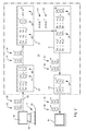
- Fig. 1 shows a block diagram with the functional units which are used for the method for qualitative assessment of a printed material 19 with at least one Identification feature are relevant.
- a color camera 01, the z. In or at one Press is fixed in place, so that with her image sensor 02 color images of the moved past the color camera 01, to be assessed material 19 preferably in is able to record ongoing printing process, is to an evaluation device 03rd connected.
- the recorded by the color camera 01, in the evaluation device 03 evaluated image data can be displayed on a color monitor 04 as needed be with the color monitor 04 in or on a belonging to the printing press Control station can be arranged.
- test procedures in the respective Signal paths preferably independent in the same evaluation device 03 run away from each other.
- the tests preferably run at least approximately at the same time off, d. H. the test procedures start at least at the same time.
- the test procedures can begin after having at least two modes of operation Evaluation device 03 changed from its learning mode 48 in its working mode 49 is.
- Each signal path relates to a functional unit 06 for testing at least the Color image of the identifying feature on a color deviation from the reference image, a Function unit 07 for checking the identifier for its affiliation to a particular class of recognition features and a functional unit 08 to Examination of the identification feature on a specific geometric contour or on a relative arrangement to at least one further identifying feature of the material 19, wherein each test one at a provided in the respective signal path Reference junction 11; 12; 13 performed comparison of the image sensor 02 of the Color camera 01 provided and suitably prepared first signal 09 with a each suitably set value 16; 17; 18, the setpoints 16; 17; 18 are stored in a data storage device 14 belonging to the evaluation device 03.
- the procedure for the qualitative assessment of a printed material 19 with at least one Identification feature relevant functional units can also be in a material 19 be implemented processing machine, this machine z.
- one Printing machine preferably a sheet-fed printing machine, in particular one Sheet-fed rotary printing machine, preferably downstream, but also upstream can.
- the material 19, d. H. a z. B. several recognition features exhibiting Sheet 19, is in the sheet-fed press at a speed of z. B. 18,000 sheets per hour and / or printed at that speed in the further processing of the printing sheets 19 processing machine.
- the Test procedures to assess the quality of the press or the Material 19 processing machine compute-intensive and the movement speed of the material 19, becomes a reliable one with the proposed method Assessment achieved.
- the method of qualitative assessment of a printed Material 19 with at least one identification feature relevant functional units in or on the printing press or the machine 19 processing the material are the location of the provision of the reference signal and the location of the are arranged Examination identical.
- the color image and its reference image can be with the same Functional units, in particular with the same color camera 01, in the same place recorded and evaluated in the same evaluation device 03.
- the color camera 01 With the color camera 01, a color image is arranged in the observation area 21, color printed material 19 added.
- the color camera 01 has a preferably as a CCD chip 02 trained image sensor 02, which in the Observation area 21 converted image information into electronic image data, the first provided by the color camera 01 or its image sensor 02 form electrical signal 09.
- each is photosensitive Pixel of the CCD chip 02 generates a signal vector 22. According to the number of Pixels of the CCD chip 02 are from the color camera 01 according to many, with a Count index identified signal vectors 22 of the evaluation 03 for Further processing provided.
- Each signal vector 22 preferably has three coefficients R, G and B.
- the Coefficients R, G and B correspond to the color values of the three signal channels red, green and blue, wherein the output from a pixel vectorial first electrical signal 09 with the recorded color of the printed material 19 at the corresponding Position in the observation area 21 correlated.
- a first correction module 23 for adjusting the color balance, the brightness and the contrast.
- each coefficient R; G; B of the signal vector 22 multiplied by a signal channel dependent correction factor K 1 , K 2, K 3 .
- a correction vector 24 with the fixed value coefficients a 1 , a 2 and a 3 is added to the resultant result vector.
- This arithmetic operation generates first corrected signal vectors 26 which improve the color balance, brightness and contrast of the image data.
- the signal channel-dependent correction factors K 1 , K 2 and K 3 and the coefficients a 1 , a 2 and a 3 of the correction vector 24 are selected such that when recording the reference gray values of black and white from the color camera 01 generated signal vectors 22 are transformed in such a way that the obtained corrected signal vectors 26 correspond to such desired values, as they result in vectors from the conversion of the known CIELAB color values.
- the multiplication results in the second corrected signal vectors 29.
- the coefficients K 4 to K 12 of the correction matrix 28 were previously determined in a suitable iteration process in such a way that the image information contained in the first corrected signal vectors 26 corresponds to the color perception of the human Be approximated.
- the second corrected signal vectors 29 are forwarded to a third correction module 31.
- the third correction module 31 signal-channel-dependent correction factors, which are multiplied by the coefficients R, G and B for adapting the intensity values which depend on the position of the respective pixels, are stored in a data memory 14 for each pixel.
- the second corrected signal vectors 29 of the first pixel are multiplied by the correction factors K 13 , K 14 and K 15 in order to calculate a third corrected signal vector 32 for the first pixel.
- This correction of the second corrected signal vectors 29 is preferably carried out for all pixels of the image sensor 02.
- the third corrected signal vectors 32 are then sent to a fourth correction module 33 forwarded.
- the coefficients R; G; B the third corrected signal vectors 32 with a factor ⁇ and then the fourth corrected signal vectors 34 calculated.
- potentiating with the factor ⁇ becomes the non-linear brightness transfer function of a color monitor 04 takes into account the fourth corrected signal vectors 34 are transmitted for display.
- the image signal is picked up by an image sensor 02 in FIG separate signal channels R; G; B.
- the signal channels R; G; B are the signal channels R; G; B around the three signal channels Red R, Green G and blue B.
- Each of the signal channels R; G; B has an adjustable spectral Sensitivity on. This has the advantage that each signal channel R; G; B in his spectral sensitivity to the spectral sensitivity of each pin of the Retina of the human eye can be adjusted.
- the spectral content of an image is analyzed on a pixel-by-pixel basis.
- the image sensor signals of the signal channels R; G; B linked together.
- each image sensor signal in the opposite color channel 38; 39 a non-linear transformation 41 subjected. This takes into account the digital nature of the electronically generated recordings.
- the generation of the output signals 43; 44 of the counter-color channels 38; 39 is analogous to the generation of the signals of the receptive fields in the human retina. That is, there is a link by means of the calculation rules 36; 37 of the signal channels R; G; B performed according to the linking of the cones of the human retina.
- the image sensor signals of the red signal channel R and the green signal channel G are combined with each other by means of the first calculation rule 36.
- the image sensor signal of the blue signal channel B is linked to the minimum 46 of the image sensor signals of the red signal channel R and of the green signal channel G by means of the calculation rule 37.
- the receptive fields of the human retina are characterized by a low-pass behavior. Accordingly, in the present embodiment, the signals obtained by linking a low-pass filtering 47, z. B. with a Gauss low pass filter subjected.
- the learning mode 48 has the goal of generating pixel-by-pixel nominal values as Reference data values in the subsequent operating mode 49 with the output signals 43; 44 of the counter-color channels 38; 39 of the corresponding pixels are compared.
- the image contents of a reference image 52 or more Reference images 52 analyzed by the fact that the image content of each pixel in three Signal channels R; G; B and a subsequent perceptual adaptation of the image signals of each signal channel R; G; B is carried out and subsequent processing of the image sensor signals after the previously described counter color method is performed.
- each pixel obtained output signals 43; 44 of the counter-color channels 38; 39 will be in one Data memory 14 stored.
- the Fluctuation tolerance can be determined either by the minimum / maximum values or the Standard deviation from the obtained data of the image contents of the reference images 52 each pixel.
- a pixel-by-pixel comparison of the output values 43 takes place; 44 of the Counter color channels 38; 39 of an inspection image 53 with the desired values from the Data storage 14 instead.
- the comparison can be made by means of a linear or nonlinear Classifier 54, in particular by means of threshold classifiers, Euclidean distance Classifiers, Bayes classifiers, fuzzy classifiers or artificial neural Networks are carried out. Then a good / bad decision takes place.
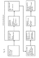
- FIG. 5 shows a flow chart for signal evaluation in the method for testing the Identification feature on its affiliation to a particular class of Recognition features.
- a grid of M x N windows 56 is formed over the entire color image to be checked where M, N> 1.
- Each window 56 is advantageously composed of mxn pixels m; n> 1.
- a square grid of N x N windows 56 is selected, where each window 56 consists of nxn pixels.
- the signal is every Window 56 tested separately.
- the two-dimensional Color image of the spatial space transformed into a two-dimensional image in the frequency domain is called frequency spectrum.
- the spectrum obtained is called frequency spectrum.
- As it is in the present Embodiment is a discrete spectrum, is also the frequency spectrum discreet.
- the frequency spectrum is determined by the spectral coefficients 59 - too Spectral values 59 called - formed.
- the amount formation 61 of the spectral values 59 takes place.
- the Amount of spectral values 59 is called spectral amplitude value 62.
- the Spectral amplitude values 62 in the present embodiment form the Characteristic values 62, d. H. they are identical to the characteristic values 62.
- the feature selection 63 As a further method step follows the feature selection 63. Aim of the feature selection 63 is to select those features 64 that are characteristic of the image content of the are to be examined color image. As features 64 are both characteristic Spectral amplitude values 62, which by their position in the frequency space and by their Amplitude define the feature 64, as well as linguistic variables such as "gray”, "black” or “white” possible.
- the fuzzification 66 the membership of each Spectral amplitude value 62 to a feature 64 by a soft or blurred Membership function 67 set; d. H. There is a weighting.
- the membership functions 67 in a learning mode as reference data sets stored setpoints can be adjusted, it makes sense if the Membership functions 67 as parameterized monomodal, d. H. dimensional Potential functions are formed, in which the parameters of the positive and negative slope separately adapted to the target values to be examined can.
- the Learning mode subsequent work mode then the Data records of the image content from which the feature values 62 of the items to be checked Color images result, weighted with the respective membership functions 67 whose Parameters were determined in the previous learning mode. Ie. it takes place for each Feature 64 is a kind of target-to-actual comparison between a reference data set stored in the Parameters of the membership functions 67 is expressed, and the record of the color image to be tested.
- the membership functions 67 is a soft or fuzzy association between the respective feature value 62 and the Feature 64 made.
- interference 68 essentially finds a conjunctive Linkage 69 - also called aggregation 69 - of all affiliation functions 67 of the Features 64, thereby creating a parent membership function 71.
- This sympathy value 73 is set in the classification 74 with a previously set Threshold 76, whereby a classification statement can be made.
- Threshold 76 is set either manually or automatically.
- the attitude the threshold value 76 also takes place in the learning mode.
- the method of testing the recognition feature for a given geometric Contour and / or on a relative arrangement to at least one other is essentially the following steps.
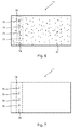
- a difference image 77 is formed, wherein in Fig. 6, only a section of the difference image 77 is shown in the area of a banknote 19. It can be seen in Fig. 6 that in Difference image 77, the normal printed image of the banknote 19 is hidden and only the Areas of the print image that differ significantly from the background reference value, as dark fields in the difference image. In a dashed line indicated strip-shaped expected area 78, the position z. B. one in the sheet introduced recognition feature 79, in particular an incorporated Filament 79, the difference image 77 according to its breakthroughs in five Darkfields 79 depicts, vary.
- Fig. 7 illustrates the difference image 77 after a suitable Binarmaschine, through which the irrelevant dark fields 81 were filtered out.
- the difference image 77 occur in the result only the resulting from the window thread 79 dark fields 79 significantly out.
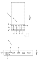
- FIG. 8 illustrates a mask reference 82 in its geometric form.
- Mask reference 82 is the data for the width 83 and the length 84 of FIG Window thread breaks 79 deposited. Further, in the mask reference 82, the values for the distance 86 between the window thread openings 79 and the number of Window thread breaks 79 deposited each banknote 19.
- the mask reference 82 is evaluated shifted by data-technical operations relative to the difference image 77 until a maximum overlap between the mask reference 82 and the Darkfields 79 in the difference image 77 results. Is this maximum of coverage reached, can from the distances 87; 88, the z. B. from the current positions in the X and Y directions the mask reference 82 relative to the edges of the banknote 19, on the current position of the window thread 79 are closed in the print image, so at a subsequent examination of the printed image, the areas of the window thread breaks 79 can be hidden.
- FIG. 10 shows a second mask reference 89, the eight window thread openings 91 corresponding dark fields 91 when testing a banknote 19 on a concave represented curved contact surface.
- FIG. 11 schematically illustrates a difference image 92 in which the Window thread openings 91 in dark fields 93, z. B. in window threads 93 shown to have.
- the dark field 94 was thereby a printing error 94 and not one Window thread break 91 caused.
- a window thread break has 91 in the middle due to the insufficient color difference between background and Window thread 93 not shown in the difference image 92.
- the mask reference 89 on a projection line 96th projected and the resulting light-dark distribution with that from the projection of the difference image 92 on a projection line 97 resulting light-dark distribution compared.
- the Position of the window thread 93 are detected in one direction.
Landscapes
- Engineering & Computer Science (AREA)
- Quality & Reliability (AREA)
- Toxicology (AREA)
- Physics & Mathematics (AREA)
- General Physics & Mathematics (AREA)
- General Health & Medical Sciences (AREA)
- Health & Medical Sciences (AREA)
- Signal Processing (AREA)
- Multimedia (AREA)
- Computer Vision & Pattern Recognition (AREA)
- Theoretical Computer Science (AREA)
- Image Analysis (AREA)
- Image Processing (AREA)
- Inspection Of Paper Currency And Valuable Securities (AREA)
- Spectrometry And Color Measurement (AREA)
Applications Claiming Priority (3)
| Application Number | Priority Date | Filing Date | Title |
|---|---|---|---|
| DE10314071A DE10314071B3 (de) | 2003-03-28 | 2003-03-28 | Verfahren zur qualitativen Beurteilung eines Materials mit mindestens einem Erkennungsmerkmal |
| DE10314071 | 2003-03-28 | ||
| EP04723616A EP1609119A2 (fr) | 2003-03-28 | 2004-03-26 | Procede d'evaluation qualitative d'une matiere presentant au moins une caracteristique d'identification |
Related Parent Applications (2)
| Application Number | Title | Priority Date | Filing Date |
|---|---|---|---|
| EP04723616.1 Division | 2004-03-26 | ||
| EP04723616A Division EP1609119A2 (fr) | 2003-03-28 | 2004-03-26 | Procede d'evaluation qualitative d'une matiere presentant au moins une caracteristique d'identification |
Publications (3)
| Publication Number | Publication Date |
|---|---|
| EP1610270A2 true EP1610270A2 (fr) | 2005-12-28 |
| EP1610270A8 EP1610270A8 (fr) | 2010-07-28 |
| EP1610270A3 EP1610270A3 (fr) | 2010-09-01 |
Family
ID=32921144
Family Applications (3)
| Application Number | Title | Priority Date | Filing Date |
|---|---|---|---|
| EP05108365A Ceased EP1610270A3 (fr) | 2003-03-28 | 2004-03-26 | Procédé d'évaluation d'un materiel avec au moins une caractéristique d'identification |
| EP05108368A Ceased EP1625936A3 (fr) | 2003-03-28 | 2004-03-26 | Procédé d'évaluation qualitative d'un matériau portant au moins une caractéristique d'identification |
| EP04723616A Ceased EP1609119A2 (fr) | 2003-03-28 | 2004-03-26 | Procede d'evaluation qualitative d'une matiere presentant au moins une caracteristique d'identification |
Family Applications After (2)
| Application Number | Title | Priority Date | Filing Date |
|---|---|---|---|
| EP05108368A Ceased EP1625936A3 (fr) | 2003-03-28 | 2004-03-26 | Procédé d'évaluation qualitative d'un matériau portant au moins une caractéristique d'identification |
| EP04723616A Ceased EP1609119A2 (fr) | 2003-03-28 | 2004-03-26 | Procede d'evaluation qualitative d'une matiere presentant au moins une caracteristique d'identification |
Country Status (6)
| Country | Link |
|---|---|
| US (1) | US7447353B2 (fr) |
| EP (3) | EP1610270A3 (fr) |
| JP (1) | JP4364239B2 (fr) |
| CN (1) | CN100403770C (fr) |
| DE (1) | DE10314071B3 (fr) |
| WO (1) | WO2004086291A2 (fr) |
Cited By (2)
| Publication number | Priority date | Publication date | Assignee | Title |
|---|---|---|---|---|
| EP2102785A4 (fr) * | 2006-09-19 | 2010-02-03 | Verichk Global Technology Inc | Appareil et procédé pour une détection sécurisée d'un article et procédé de sécurisation d'accès à des informations associées à l'article |
| EP2199986A1 (fr) * | 2008-12-22 | 2010-06-23 | Giesecke & Devrient GmbH | Procédé et dispositif d'enregistrement des caractéristiques optiques d'un document de valeur |
Families Citing this family (41)
| Publication number | Priority date | Publication date | Assignee | Title |
|---|---|---|---|---|
| US7502116B2 (en) * | 2003-09-09 | 2009-03-10 | Hewlett-Packard Development Company, L.P. | Densitometers and methods for measuring optical density |
| US7460737B2 (en) * | 2004-02-12 | 2008-12-02 | Hoshiko Llc | Method and apparatus for photograph finding |
| DE102004019978B3 (de) | 2004-04-23 | 2005-08-04 | Koenig & Bauer Ag | Verfahren zur Beurteilung einer Qualität einer von einer Druckmaschine produzierten Drucksache |
| DE102004021047B3 (de) * | 2004-04-29 | 2005-10-06 | Koenig & Bauer Ag | Verfahren zum Vergleich eines Bildes mit mindestens einem Referenzbild |
| DE102005001091B3 (de) * | 2005-01-06 | 2006-04-06 | Lpcon Gmbh | Verfahren und Anordnung zur Fehlererkennung an Druckbildern während der Bahnbeobachtung von gedrucktem Material |
| DE102005031957B4 (de) | 2005-07-08 | 2007-03-22 | Koenig & Bauer Ag | Vorrichtung zur Inspektion eines Bedruckstoffes mit uneinheitlich reflektierenden Oberflächen |
| JP4273108B2 (ja) * | 2005-09-12 | 2009-06-03 | キヤノン株式会社 | 色処理方法、色処理装置及び記憶媒体 |
| US8717647B2 (en) | 2005-10-13 | 2014-05-06 | Hewlett-Packard Development Company, L.P. | Imaging methods, imaging device calibration methods, imaging devices, and hard imaging device sensor assemblies |
| US7894677B2 (en) * | 2006-02-09 | 2011-02-22 | Microsoft Corporation | Reducing human overhead in text categorization |
| US7756289B2 (en) * | 2006-03-22 | 2010-07-13 | Ancestry.Com Operations Inc. | Image watermarking systems and methods |
| DE102006022529B4 (de) | 2006-05-15 | 2009-05-20 | Koenig & Bauer Aktiengesellschaft | Rollenrotationsdruckmaschine mit mindestens einem Farbwerk und mit einem Inline-Inspektionssystem |
| US7840060B2 (en) * | 2006-06-12 | 2010-11-23 | D&S Consultants, Inc. | System and method for machine learning using a similarity inverse matrix |
| WO2008129540A2 (fr) * | 2007-04-19 | 2008-10-30 | Eyecue Vision Technologies Ltd. | Dispositif et procédé pour l'identification d'objets en utilisant un codage de couleurs |
| US8134717B2 (en) * | 2010-05-21 | 2012-03-13 | LTS Scale Company | Dimensional detection system and associated method |
| JP5423702B2 (ja) | 2011-02-15 | 2014-02-19 | 株式会社デンソー | 画像処理装置及びその調整方法 |
| DE102011016509A1 (de) | 2011-04-08 | 2012-10-11 | Giesecke & Devrient Gmbh | Verfahren zur Prüfung von Wertdokumenten |
| DE102011121877A1 (de) * | 2011-12-21 | 2013-06-27 | Giesecke & Devrient Gmbh | Verfahren und Vorrichtung zur Bestimmung von Klassifizierungsparametern für die Klassifizierung von Banknoten |
| US9830523B2 (en) | 2012-05-31 | 2017-11-28 | Korea Institute Of Science And Technology | Method and apparatus for recognizing object material using spatial image and spatial radar information |
| US9407776B2 (en) * | 2013-08-13 | 2016-08-02 | Technology Watch, LLC | Method for evaluation of printing and imaging systems that grade attributes of an image evaluation document produced by such systems |
| JP6403391B2 (ja) | 2014-01-27 | 2018-10-10 | グローリー株式会社 | 紙幣処理装置及び紙幣処理方法 |
| JP6396066B2 (ja) * | 2014-04-10 | 2018-09-26 | 株式会社東芝 | 画質改善システム、画質改善方法及びプログラム |
| DE102014015746A1 (de) * | 2014-10-24 | 2016-04-28 | Giesecke & Devrient Gmbh | Vorrichtung und Verfahren zur Prüfung von Wertdokumenten, insbesondere Banknoten, sowie Wertdokumentbearbeitungssystem |
| US9582739B2 (en) * | 2014-11-18 | 2017-02-28 | Harry Friedbert Padubrin | Learning contour identification system using portable contour metrics derived from contour mappings |
| CN104732644B (zh) * | 2015-01-19 | 2017-10-31 | 广州广电运通金融电子股份有限公司 | 纸币鉴别的质量控制方法及其系统 |
| CN104574642B (zh) * | 2015-01-30 | 2017-04-26 | 广州广电运通金融电子股份有限公司 | 一种基于Lab色彩空间的人民币变色油墨检测方法和装置 |
| US10838376B2 (en) * | 2015-09-10 | 2020-11-17 | I.Systems Automação Industrial S.A | Method of generating fuzzy knowledge base for a programmable fuzzy controller |
| TWI576533B (zh) * | 2016-08-04 | 2017-04-01 | 中華大學 | Intelligent adaptive lighting system |
| US11425281B1 (en) * | 2016-09-07 | 2022-08-23 | Google Llc | Color image processing using models of overlapped response spectra for retinal cone cells |
| CN108415915A (zh) * | 2017-02-10 | 2018-08-17 | 深圳怡化电脑股份有限公司 | 一种基于纸币数据的算法验证方法及装置 |
| US10769817B2 (en) * | 2017-08-07 | 2020-09-08 | Samsung Display Co., Ltd. | Measures for image testing |
| JP6842177B2 (ja) * | 2018-04-06 | 2021-03-17 | 旭精工株式会社 | 硬貨識別方法、硬貨識別システム及び硬貨識別プログラム |
| CN109016864B (zh) * | 2018-09-11 | 2020-02-21 | 大连理工大学 | 一种精准定位静电打印系统和方法 |
| WO2020079567A1 (fr) * | 2018-10-15 | 2020-04-23 | 3M Innovative Properties Company | Inspection automatisée de parties de feuille de forme arbitraire à partir d'un film fabriqué |
| JP7078175B2 (ja) * | 2019-03-15 | 2022-05-31 | オムロン株式会社 | 検査装置及び方法 |
| DE102019120938B4 (de) * | 2019-08-02 | 2023-12-21 | Bundesdruckerei Gmbh | Druckinspektionsvorrichtung und Verfahren zur optischen Inspektion eines Druckbildes eines Druckobjekts |
| WO2021155000A1 (fr) | 2020-01-29 | 2021-08-05 | ReportsNow, Inc. | Systèmes, procédés et dispositifs de traitement d'image |
| JP7482662B2 (ja) * | 2020-03-25 | 2024-05-14 | 東京エレクトロン株式会社 | 異常検出装置及び異常検出方法 |
| US11158031B1 (en) | 2021-05-24 | 2021-10-26 | ReportsNow, Inc. | Systems, methods, and devices for image processing |
| CN114708961A (zh) * | 2022-03-18 | 2022-07-05 | 北京理工大学珠海学院 | 个人生理和心理特性类别测评装置及方法 |
| CN115588094A (zh) * | 2022-10-19 | 2023-01-10 | 浙江纺织服装职业技术学院 | 一种基于深度学习的工业机器人视觉图像识别方法及系统 |
| DE102022133947A1 (de) * | 2022-12-19 | 2024-06-20 | Manroland Goss Web Systems Gmbh | Verfahren zur Positionsbestimmung von Spektralmessungen |
Citations (1)
| Publication number | Priority date | Publication date | Assignee | Title |
|---|---|---|---|---|
| DE3639636A1 (de) * | 1986-11-20 | 1988-05-26 | Robert Prof Dr Ing Massen | Automatische inspektion von textilbahnen |
Family Cites Families (27)
| Publication number | Priority date | Publication date | Assignee | Title |
|---|---|---|---|---|
| EP0540833B1 (fr) * | 1991-08-12 | 1997-04-23 | KOENIG & BAUER-ALBERT AKTIENGESELLSCHAFT | ContrÔle de qualité d'une image, par exemple un modèle imprimé |
| DE4136461C2 (de) * | 1991-11-06 | 1999-04-08 | Roland Man Druckmasch | Vorrichtung und Verfahren zur großflächigen Bildinspektion |
| JPH07117498B2 (ja) * | 1991-12-11 | 1995-12-18 | インターナショナル・ビジネス・マシーンズ・コーポレイション | 検査システム |
| CH684222A5 (de) * | 1992-03-10 | 1994-07-29 | Mars Inc | Einrichtung zur Klassifizierung eines Musters, insbesondere von einer Banknote oder von einer Münze. |
| DE4393748C5 (de) * | 1992-08-03 | 2004-08-26 | Ricoh Co., Ltd. | Vorlagen-Unterscheidungssystem |
| EP0664642B1 (fr) * | 1994-01-20 | 2002-07-24 | Omron Corporation | Dispositif de traitement d'images d'identification d'une image d'entrée et appareil à copier équipé de celui-ci |
| US5602938A (en) * | 1994-05-20 | 1997-02-11 | Nippon Telegraph And Telephone Corporation | Method of generating dictionary for pattern recognition and pattern recognition method using the same |
| DE19613082C2 (de) * | 1996-04-02 | 1999-10-21 | Koenig & Bauer Ag | Verfahren und Vorrichtung zur qualitativen Beurteilung von bearbeitetem Material |
| AUPO542897A0 (en) * | 1997-03-03 | 1997-03-27 | Meat Research Corporation | Calibration of imaging system |
| JPH1141478A (ja) | 1997-07-24 | 1999-02-12 | Canon Inc | 画像処理方法、装置および記録媒体 |
| US7158144B2 (en) * | 1997-07-09 | 2007-01-02 | Canon Kabushiki Kaisha | Image processing apparatus and method for converting data dependent on a first illuminating light into data dependent on a second illuminating light |
| JP3862374B2 (ja) * | 1997-09-04 | 2006-12-27 | キヤノン株式会社 | 画像処理装置及び方法 |
| DE19802781A1 (de) * | 1998-01-26 | 1999-07-29 | Peter L Prof Dr Andresen | Schnelle Identifizierung von wertvollen Objekten durch digitale Bildanalytik |
| DE19817878A1 (de) * | 1998-04-22 | 1999-11-04 | Juerg Paul Haller | Verfahren zur Herstellung von Drucksendungen, Einrichtung zur Herstellung von Drucksendungen, Umhüllung für eine nach dem Verfahren hergestellte Drucksendung sowie ein zur Verwendung bei einem solchen Verfahren hergestelltes Kuvert |
| US6069973A (en) * | 1998-06-30 | 2000-05-30 | Xerox Corporation | Method and apparatus for color correction in a multi-chip imaging array |
| US6594392B2 (en) * | 1999-05-17 | 2003-07-15 | Intel Corporation | Pattern recognition based on piecewise linear probability density function |
| US6580820B1 (en) * | 1999-06-09 | 2003-06-17 | Xerox Corporation | Digital imaging method and apparatus for detection of document security marks |
| JP2001016607A (ja) | 1999-06-29 | 2001-01-19 | Minolta Co Ltd | デジタル撮影装置およびデジタル撮影方法 |
| US6516078B1 (en) * | 1999-07-29 | 2003-02-04 | Hewlett-Packard Company | Multi-level detection and deterrence of counterfeiting of documents with reduced false detection |
| IL131282A (en) * | 1999-08-05 | 2009-02-11 | Orbotech Ltd | Apparatus and methods for inspection of objects |
| JP2001129985A (ja) * | 1999-08-24 | 2001-05-15 | Canon Inc | プリント位置調整方法並びに該方法を用いるプリント装置およびプリントシステム |
| DE19940879A1 (de) * | 1999-08-27 | 2001-03-08 | Innomess Elektronik Gmbh | Verfahren und Vorrichtung zum automatisierten Vergleich von Druckbildern an Druckmaschinen |
| DE20010920U1 (de) | 2000-06-20 | 2000-09-14 | MAN Roland Druckmaschinen AG, 63075 Offenbach | Druckmaschine, insbesondere Bogenoffsetdruckmaschine |
| DE10132589B4 (de) * | 2001-07-05 | 2005-11-03 | Koenig & Bauer Ag | Verfahren zur qualitativen Beurteilung von Material |
| JP4006224B2 (ja) * | 2001-11-16 | 2007-11-14 | キヤノン株式会社 | 画像品質判定方法、判定装置、判定プログラム |
| DE10234086B4 (de) * | 2002-07-26 | 2004-08-26 | Koenig & Bauer Ag | Verfahren zur Signalauswertung eines elektronischen Bildsensors bei der Mustererkennung von Bildinhalten eines Prüfkörpers |
| DE20303574U1 (de) | 2003-03-06 | 2003-04-30 | MAN Roland Druckmaschinen AG, 63075 Offenbach | Bildinspektionssystem für eine Druckmaschine |
-
2003
- 2003-03-28 DE DE10314071A patent/DE10314071B3/de not_active Withdrawn - After Issue
-
2004
- 2004-03-26 EP EP05108365A patent/EP1610270A3/fr not_active Ceased
- 2004-03-26 CN CNB2004800147354A patent/CN100403770C/zh not_active Expired - Fee Related
- 2004-03-26 EP EP05108368A patent/EP1625936A3/fr not_active Ceased
- 2004-03-26 JP JP2006505497A patent/JP4364239B2/ja not_active Expired - Fee Related
- 2004-03-26 EP EP04723616A patent/EP1609119A2/fr not_active Ceased
- 2004-03-26 WO PCT/EP2004/050378 patent/WO2004086291A2/fr not_active Ceased
- 2004-03-26 US US10/550,889 patent/US7447353B2/en not_active Expired - Fee Related
Patent Citations (1)
| Publication number | Priority date | Publication date | Assignee | Title |
|---|---|---|---|---|
| DE3639636A1 (de) * | 1986-11-20 | 1988-05-26 | Robert Prof Dr Ing Massen | Automatische inspektion von textilbahnen |
Cited By (3)
| Publication number | Priority date | Publication date | Assignee | Title |
|---|---|---|---|---|
| EP2102785A4 (fr) * | 2006-09-19 | 2010-02-03 | Verichk Global Technology Inc | Appareil et procédé pour une détection sécurisée d'un article et procédé de sécurisation d'accès à des informations associées à l'article |
| US8542094B2 (en) | 2006-09-19 | 2013-09-24 | Verichk Global Technology Inc. | Apparatus and method for secure detection of an item and a method of securing access to information associated with the item |
| EP2199986A1 (fr) * | 2008-12-22 | 2010-06-23 | Giesecke & Devrient GmbH | Procédé et dispositif d'enregistrement des caractéristiques optiques d'un document de valeur |
Also Published As
| Publication number | Publication date |
|---|---|
| WO2004086291A2 (fr) | 2004-10-07 |
| DE10314071B3 (de) | 2004-09-30 |
| US7447353B2 (en) | 2008-11-04 |
| EP1625936A2 (fr) | 2006-02-15 |
| EP1609119A2 (fr) | 2005-12-28 |
| EP1610270A3 (fr) | 2010-09-01 |
| CN1795467A (zh) | 2006-06-28 |
| CN100403770C (zh) | 2008-07-16 |
| EP1610270A8 (fr) | 2010-07-28 |
| WO2004086291A3 (fr) | 2005-01-20 |
| EP1625936A8 (fr) | 2010-07-28 |
| US20060251320A1 (en) | 2006-11-09 |
| JP2006524378A (ja) | 2006-10-26 |
| EP1625936A3 (fr) | 2010-09-08 |
| JP4364239B2 (ja) | 2009-11-11 |
Similar Documents
| Publication | Publication Date | Title |
|---|---|---|
| DE10314071B3 (de) | Verfahren zur qualitativen Beurteilung eines Materials mit mindestens einem Erkennungsmerkmal | |
| EP0012724B1 (fr) | Procédé mécanisé d'estimation de la qualité d'impression d'un produit imprimé ainsi que dispositf pour sa mise en oeuvre | |
| DE69326502T2 (de) | Vorrichtung zur Prüfung von Produkten | |
| DE102007033835B4 (de) | Bildaufnahmetechnik zur direkten Objektsegmentierung in Bildern | |
| DE102011106050A1 (de) | Schattenentfernung in einem durch eine fahrzeugbasierte Kamera erfassten Bild zur Detektion eines freien Pfads | |
| WO2008058742A1 (fr) | Procédé de détection des encrassements et/ou l'usure de l'encre dans la zone des transitions de couleur sur des documents de valeur et moyens en vue de mettre en œuvre le procédé | |
| DE102010037746A1 (de) | Verfahren zum optischen Antasten einer Kante in oder an einem Oberflächenbereich | |
| DE102010047948A1 (de) | Verfahren zum Prüfen eines optischen Sicherheitsmerkmals eines Wertdokuments | |
| DE102016216795A1 (de) | Verfahren zur Ermittlung von Ergebnisbilddaten | |
| EP2761604A1 (fr) | Procédé de contrôle de la qualité de fabrication d'une caractéristique de sécurité d'un document de valeur | |
| EP0012723B1 (fr) | Procédé d'examen mécanique de la qualité d'impression d'une épreuve et dispositif pour sa mise en action | |
| DE102016100134A1 (de) | Verfahren und Vorrichtung zum Untersuchen eines Objekts unter Verwendung von maschinellem Sehen | |
| DE102012200930A1 (de) | Vorrichtung und Verfahren zum Erfassen einer Pflanze vor einem Hintergrund | |
| WO2000013143A1 (fr) | Procede et dispositif de detection des couleurs d'un objet | |
| DE102004021047B3 (de) | Verfahren zum Vergleich eines Bildes mit mindestens einem Referenzbild | |
| EP3771564B1 (fr) | Dispositif d'inspection d'impression et procédé d'inspection optique d'une image imprimée d'un objet imprimé | |
| DE202004020463U1 (de) | Systeme zur Beurteilung einer Qualität einer von einer Druckmaschine produzierten Drucksache | |
| EP2394250A1 (fr) | Procédé et dispositif pour vérifier des documents par utilisation d'une transformation en ondelettes | |
| DE102021130505B4 (de) | Verfahren zur Bestimmung einer Beleuchtungsfarbe, Bildverarbeitungsvorrichtung und Aufnahmesystem | |
| DE2217281A1 (de) | Dichtenmessung durch Bildanalyse. > | |
| DE19742152A1 (de) | Bildsystem für eine medizinische Diagnostikeinrichtung und Verfahren zur gefensterten Darstellung von medizinischen Bildern | |
| DE112017001026T5 (de) | Verfahren und System zur ldentifizierung und Messung eines Defekts, der die Transparenz in einem Substrat für ein Sicherheitsdokument verringert | |
| EP3220112B1 (fr) | Dispositif comprenant au mois un module de capteur optique et procédé de fonctionnement associé | |
| EP4205091A1 (fr) | Procédé pour produire un identifiant numérique d'un exemplaire d'un produit d'impression, ledit exemplaire présentant au moins une image d'impression, téléphone intelligent ou tablette doté(e) d'un tel dispositif et procédé d'utilisation de ce dispositif | |
| AT514660A1 (de) | Verfahren zur Prüfung eines Gegenstands auf Echtheit |
Legal Events
| Date | Code | Title | Description |
|---|---|---|---|
| PUAI | Public reference made under article 153(3) epc to a published international application that has entered the european phase |
Free format text: ORIGINAL CODE: 0009012 |
|
| AC | Divisional application: reference to earlier application |
Ref document number: 1609119 Country of ref document: EP Kind code of ref document: P |
|
| AK | Designated contracting states |
Kind code of ref document: A2 Designated state(s): AT BE BG CH CY CZ DE DK EE ES FI FR GB GR HU IE IS IT LI LT LU LV MC NL PL PT RO SE SI SK TR |
|
| AX | Request for extension of the european patent |
Extension state: AL BA HR MK YU |
|
| PUAL | Search report despatched |
Free format text: ORIGINAL CODE: 0009013 |
|
| AK | Designated contracting states |
Kind code of ref document: A3 Designated state(s): AT BE BG CH CY CZ DE DK EE ES FI FR GB GR HU IE IT LI LU MC NL PL PT RO SE SI SK TR |
|
| AX | Request for extension of the european patent |
Extension state: BA HR YU |
|
| 17P | Request for examination filed |
Effective date: 20100806 |
|
| AKX | Designation fees paid |
Designated state(s): AT BE BG CH CY CZ DE DK EE ES FI FR GB GR HU IE IT LI LU MC NL PL PT RO SE SI SK TR |
|
| 17Q | First examination report despatched |
Effective date: 20130516 |
|
| STAA | Information on the status of an ep patent application or granted ep patent |
Free format text: STATUS: THE APPLICATION HAS BEEN REFUSED |
|
| 18R | Application refused |
Effective date: 20131223 |