EP1610320A2 - Appareil d'enregistrement optique et méthode de commande de la durée de l'enregistrement - Google Patents
Appareil d'enregistrement optique et méthode de commande de la durée de l'enregistrement Download PDFInfo
- Publication number
- EP1610320A2 EP1610320A2 EP05252848A EP05252848A EP1610320A2 EP 1610320 A2 EP1610320 A2 EP 1610320A2 EP 05252848 A EP05252848 A EP 05252848A EP 05252848 A EP05252848 A EP 05252848A EP 1610320 A2 EP1610320 A2 EP 1610320A2
- Authority
- EP
- European Patent Office
- Prior art keywords
- write
- writing
- execution time
- request signal
- write execution
- Prior art date
- Legal status (The legal status is an assumption and is not a legal conclusion. Google has not performed a legal analysis and makes no representation as to the accuracy of the status listed.)
- Ceased
Links
Images


Classifications
-
- G—PHYSICS
- G11—INFORMATION STORAGE
- G11B—INFORMATION STORAGE BASED ON RELATIVE MOVEMENT BETWEEN RECORD CARRIER AND TRANSDUCER
- G11B7/00—Recording or reproducing by optical means, e.g. recording using a thermal beam of optical radiation by modifying optical properties or the physical structure, reproducing using an optical beam at lower power by sensing optical properties; Record carriers therefor
- G11B7/004—Recording, reproducing or erasing methods; Read, write or erase circuits therefor
- G11B7/0045—Recording
-
- G—PHYSICS
- G11—INFORMATION STORAGE
- G11B—INFORMATION STORAGE BASED ON RELATIVE MOVEMENT BETWEEN RECORD CARRIER AND TRANSDUCER
- G11B7/00—Recording or reproducing by optical means, e.g. recording using a thermal beam of optical radiation by modifying optical properties or the physical structure, reproducing using an optical beam at lower power by sensing optical properties; Record carriers therefor
- G11B7/007—Arrangement of the information on the record carrier, e.g. form of tracks, actual track shape, e.g. wobbled, or cross-section, e.g. v-shaped; Sequential information structures, e.g. sectoring or header formats within a track
- G11B7/00736—Auxiliary data, e.g. lead-in, lead-out, Power Calibration Area [PCA], Burst Cutting Area [BCA], control information
-
- G—PHYSICS
- G11—INFORMATION STORAGE
- G11B—INFORMATION STORAGE BASED ON RELATIVE MOVEMENT BETWEEN RECORD CARRIER AND TRANSDUCER
- G11B19/00—Driving, starting, stopping record carriers not specifically of filamentary or web form, or of supports therefor; Control thereof; Control of operating function ; Driving both disc and head
- G11B19/02—Control of operating function, e.g. switching from recording to reproducing
- G11B19/06—Control of operating function, e.g. switching from recording to reproducing by counting or timing of machine operations
-
- G—PHYSICS
- G11—INFORMATION STORAGE
- G11B—INFORMATION STORAGE BASED ON RELATIVE MOVEMENT BETWEEN RECORD CARRIER AND TRANSDUCER
- G11B19/00—Driving, starting, stopping record carriers not specifically of filamentary or web form, or of supports therefor; Control thereof; Control of operating function ; Driving both disc and head
- G11B19/02—Control of operating function, e.g. switching from recording to reproducing
- G11B19/16—Manual control
-
- G—PHYSICS
- G11—INFORMATION STORAGE
- G11B—INFORMATION STORAGE BASED ON RELATIVE MOVEMENT BETWEEN RECORD CARRIER AND TRANSDUCER
- G11B7/00—Recording or reproducing by optical means, e.g. recording using a thermal beam of optical radiation by modifying optical properties or the physical structure, reproducing using an optical beam at lower power by sensing optical properties; Record carriers therefor
Definitions
- the present invention generally relates to an optical writing apparatus and a method to control the write execution time. More particularly, the present invention relates to an optical writing apparatus to decrement or maintain its write execution time during a pause period when the pause period is required while write data are written onto a writing medium by setting the write execution time, and a method to control its write execution time.
- An optical writing apparatus employs an optical disk driver to allow data to be written onto an optical disk.
- data to be written onto the optical disk are written in a stream form, thus providing videos and sounds of high quality.
- FIG. 1 is a schematic view for illustrating a conventional optical writing apparatus.
- the optical writing apparatus includes a front panel 100 wherein a key input portion 110 is included to receive operating instructions corresponding to selection or setting of various functions, which are input by a user.
- the front panel 100 further includes a display 120 to display operations in progress and functions selected by the user, and a tray 130 to load and unload an optical disk (not shown).
- a plurality of function keys 110a to 110g are typically arranged in the key input portion 110.
- the function keys 110a to 110g include a PLAY key 110a to reproduce images and sounds stored in the optical disk, a RECORD key 110b to perform a writing operation to write data to the optical disk, a STOP key 110c to stop the operation in progress, a PAUSE key 110d to pause the operation in progress, an OPEN/CLOSE key 110e to open or close the tray 130, a rewind key 110f, a fast forward key 110g, and direction keys 110h to select up, down, right and left directions in a menu.
- the user After the user operates the OPEN/CLOSE key 110e to load the writing medium (i.e., the optical disk) onto the optical writing apparatus, the user operates the RECORD key 110b to allow write data to be written onto the writing medium.
- the user may operate the direction keys 110h to set a writing time when the write data are written onto the writing medium using the menu provided in the optical writing apparatus.
- the optical writing apparatus gradually decrements the write execution time while the writing operation is in progress, and stops the writing operation when the write execution time reaches zero.
- the user When the user does not pay attention to the writing operation or when contents that the user does not want to write are provided from an external equipment connected to the optical writing apparatus, the user operates the PAUSE key 100d to pause the writing operation.
- the conventional optical writing apparatus decrements the preset write execution time in a paused state of the writing operation as is done in a state of the writing operation, or does not allow the write execution time to be decremented in the paused state of the writing operation.
- functions of decrementing and maintaining the write execution time in the paused state are predetermined to allow performance of any one of these functions in the paused state of the conventional optical writing apparatus.
- the present invention provides an optical writing apparatus and a method to control its write execution time, which gradually decrements or does not decrement the write execution time in the paused state of the writing operation when the pause operation is required during the writing operation in the optical writing apparatus.
- an optical writing apparatus comprises a pickup to write write data onto a writing medium; a servo driving portion to control the drive of the pickup; a counter to count a predetermined write execution time and to notify an ending time of the write execution time; a key input portion to which at least one request signal is applied; and a controller to control the servo driving portion until the controller is notified of an ending time of the counter to allow the write data to be written onto the writing medium when a write request signal is applied from the key input portion, and to stop the write operation and control the count of the counter to change the ending time of the write execution time when the request signal to pause the write operation is applied from the key input portion.
- the controller is operable to control the count of the counter to be stopped after the controller stops the write operation.
- the controller is operable to control the counter to continue counting after the controller stops the write operation.
- the controller is operable to allow the write data to be written onto the writing medium by controlling the servo driving portion when a write request signal is applied from the key input portion in the stopped state of the writing operation.
- the controller is operable to allow the writing operation to be stopped by controlling the servo driving portion when the controller is notified of an ending time of the write execution time from the counter.
- a method to control a write execution time of an optical writing apparatus comprises applying a write request signal; setting a predetermined write execution time for write data to be written onto a writing medium; writing the write data onto the writing medium; counting the predetermined write execution time from the time that the write data are written onto the writing medium; determining whether the write execution time is counted while the writing is paused when the write request signal for pausing the writing is applied; stopping the writing of the write data; and changing an ending time of the write execution time in response to the determination of the write execution time.
- an ending time of the write execution time is incremented by an amount of time corresponding to the paused writing period when stopping counting is determined.
- the determining whether the write execution time is counted, the ending time of the write execution time is not changed when continuing the counting is determined.
- the write request signal is applied in the paused state of the writing operation, the method further comprises writing the write data onto the writing medium.
- the method further comprises stopping the writing operation.
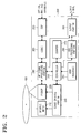
- FIG. 2 is a block diagram of an optical writing apparatus in accordance with an exemplary embodiment of the present invention.
- An optical writing apparatus 200 writes predetermined write data onto an optical disk 400, and it may be connected to various image sources such as a computer, a broadcast receiving antenna, a TV, and/or a hard disk drive or other attached reproducing player such as a camcorder.
- a Digital Video Disk (DVD) recorder may be exemplified for the optical writing apparatus.
- DVD Digital Video Disk
- other media such as Compact Discs, Blu-ray discs, Advanced Optical Disks, and/or magneto optical disks may be used.
- the optical writing apparatus 200 includes a spindle motor 210, a pickup 220, a servo driving portion 230, a Radio Frequency (RF) signal processing portion 240, a Digital Signal Processor (DSP) 250, a codec 260, a counter 270, a user interface 280, an On Screen Display (OSD) processing portion 290, an output portion 300, and a controller 310.
- RF Radio Frequency
- DSP Digital Signal Processor
- codec 260 codec 260
- counter 270 Counter 270
- OSD On Screen Display
- the spindle motor 210 rotates the optical disk 400 to be loaded.
- the pickup 220 writes signals processed by the DSP 250, the codec 260, and the RF signal processing portion 240 onto the optical disk 400. While not required, the optical pickup 220 reads out written signals such that the apparatus further reproduces the optical disk 400.
- the servo driving portion 230 controls driving the pickup 220 and the spindle motor 210.
- the RF signal processing portion 240 filters and shapes signals detected by the pickup 220, outputs the filtered and shaped signals through the output portion 300 as binary signals, and provides signals input from the codec 260 to the pickup 220.
- the DSP 250 converts the write data input to the optical writing apparatus 200 to digital data, and performs signal processing such as error correction to convert them into write formats.
- the codec 260 encodes the write data of the write format converted by the DSP 250 and decodes the encoded data, wherein output values of the codec 260 are input to the RF signal processing portion 240.
- the counter 270 counts the write execution time under the control of the controller 310, and notifies an ending time of the write execution time.
- the counting of the write execution time may be classified into one method to decrement the time from a predetermined time in a step-by-step manner and the other method to increment the time toward the predetermined time in the step-by-step manner.
- the former method will be described in the present embodiment, but it is understood that either method, or combinations thereof, may be used.
- the user interface 280 applies key operating signals applied from the user through the key input portion 110 to the controller 310.
- the key input portion 110 may be arranged in the front panel 100 of the optical writing apparatus as shown in FIG. 1, may be a remote controller (not shown) to transmit infrared signals corresponding to respective request signals, or may be otherwise received by the apparatus, such as across a network.
- the controller 310 is applied with a reproduction request signal from the PLAY key 110a, a writing/writing resume request signal from the RECORD key 110b, a stop request signal from the STOP key 110c, a pause request signal from the PAUSE key 110d, an open/close request signal from the OPEN/CLOSE key 110e, a rewind request signal from the rewind key 110f, and a fast forward request signal from the fast forward key 110g.
- up, down, right and left direction keys 110h may be further arranged to set the menu with respect to various functions of the optical writing apparatus 200.
- the OSD processing portion 290 adds the OSD menu function to allow the user to set the write execution time of his/her own will.
- the output portion 300 provides the OSD menu processed by the OSD processing portion 290 to the user.
- Output signals which correspond to the OSD menu output from the output portion 300 may be displayed on an external equipment that is connected to the optical writing apparatus 200, which allows the user to move the direction keys 110h to up, down, right and left directions to thus set the write execution time. While not required, it is understood that the apparatus may be integral with the output device, such as in a combined recorder-display.
- the set write execution time is input to the controller 310 through the user interface 280.
- the controller 310 allows the write data to be written onto the optical disk 400 by controlling the servo driving portion 230 until the controller 310 is notified of the ending time of the write execution time when a write request signal is applied from the user interface 280 through the RECORD key 110b of the key input portion 110.
- the controller 310 allows the writing operation to be stopped by controlling the servo driving portion 230 when a stop request signal and a pause request signal are applied from the user interface 280 through the STOP key 110c and the PAUSE key 110d of the key input portion 110.
- the controller 310 allows the write data to be written onto the optical disk 400 by controlling the servo driving portion 230 when a request signal to resume the write is applied from the user interface 280 through the RECORD key 110b of the key input portion 110 in the pause state of the writing operation.
- the controller 310 allows the time counting to be decremented from the write execution time in a step-by-step manner by controlling the counter 270 when the write execution time is input from the user interface 280 through the direction keys 110h of the key input portion 110.
- the controller 310 allows the counting of the write execution time to be continued by controlling the counter 270 in the case that the counting of the write execution time needs to be continued even when the writing operation is in a paused period.
- the ending time of the write execution time is not changed in this case.
- the controller 310 allows the counting operation to be paused by controlling the counter 270 when the predetermined write execution time is maintained during the paused period of the writing operation.
- the ending time of the write execution time is incremented by an amount of time corresponding to the paused period of the writing operation in this case.
- the controller 310 controls the servo driving portion 230 to stop the writing operation when the write execution time is expired (that is, when it reaches the time of zero) by the counter 270.
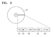
- FIG. 3 is a diagram illustrating a data structure of the optical disk shown in FIG. 2.
- Typical examples of the optical disk 400 may include storage media such as CD ⁇ R and DVD ⁇ R which allow one time writing to be carried out, and CD ⁇ RW, DVD ⁇ RW, or DVD-RAM which allows repeatable writing to be carried out.
- storage media such as CD ⁇ R and DVD ⁇ R which allow one time writing to be carried out, and CD ⁇ RW, DVD ⁇ RW, or DVD-RAM which allows repeatable writing to be carried out.
- other media such as magnetic, magneto optical, as well as other types of optical media such as Blu-ray disks and Advanced Optical Disks.
- the optical disk includes a Power Calibration Area (PCA) 410, a Record Management Area (RMA) 420, a Lead-in Area (L/I Area) 430, a Data Area 440, and a Lead-out Area (L/O) Area 450.
- PCA Power Calibration Area
- RMA Record Management Area
- L/I Area Lead-in Area
- L/O Lead-out Area
- Write data applied from external equipment are applied through the optical writing apparatus 200 to an optical disk 400 that includes a plurality of such areas. While described as external equipment, it is understood that the apparatus may include the other equipment, such as in the case of DVD-VHS players and DVD recorders having television tuners.
- FIG. 4 is a flowchart illustrating operations of a method to control a write execution time of the optical writing apparatus in accordance with an exemplary embodiment of the present invention.
- the method to control the write execution time of the optical writing apparatus according to the exemplary embodiment of the present invention will be described with reference to FIG. 1 to FIG. 4.
- a write request signal is applied from the user interface 280 to the controller 310 at operation 500.
- the controller 310 controls the OSD processing portion 290 to allow the OSD menu to set the write execution time to be provided to the user through the output portion 300, and the user operates the direction key 110h to set the write execution time needed to write the write data onto the optical disk 400 at operation 510.
- the controller 310 controls the servo driving portion 230 to allow the write data to be written onto the optical disk 400 at operation 520.
- the controller 310 controls the counter 270 to start counting to decrement the predetermined write execution time at operation 530.
- the inquiry of determining the count for the write execution time is delivered using the OSD menu through the OSD processing portion 290 and the output portion 300. However, it is understood that the inquiry may be otherwise made, such as using another display on the apparatus (such as the display 120 of FIG. 1) or another display associated with the apparatus.
- the controller 310 controls the servo driving portion 230 to stop the writing operation, and allows the counter 270 to continue counting at operation 560. In this case, the ending time of the write execution time is not changed.
- the controller 310 controls the servo driving portion 230 to resume the writing operation when a request signal to resume the writing operation is applied from the user interface 280 at operation 570.
- the controller 310 controls the servo driving portion 230 to stop the writing operation, and controls the counter 270 to pause the counting for the write execution time at operation 580.
- the ending time of the write execution time is incremented by an amount of time corresponding to the paused writing time period.
- the controller 310 controls the servo driving portion 230 to stop the writing operation at operation 610.
- the optical writing apparatus and the method to control its write execution time enables the user to select, readily, whether to continue or to stop the count of the writing execution time during the pause period when the pause period is required while write data are written onto a writing medium. When the count ends, the writing operation automatically terminates, thus providing convenience for the usage of the optical writing apparatus.
- the present invention may also be embodied as computer readable codes on a computer readable recording medium.
- the computer readable recording medium is any data storage device that may store data which may be thereafter read by a computer systemhaving at least one general and/or special purpose computer. Examples of the computer readable recording medium include read-only memory (ROM), random-access memory (RAM), CD-ROMs, magnetic tapes, floppy disks, optical data storage devices, and carrier waves (such as data transmission through the Internet).
- the computer readable recording medium may also be distributed over network coupled computer systems so that the computer readable code is stored and executed in a distributed fashion.
Landscapes
- Optical Recording Or Reproduction (AREA)
- Signal Processing For Digital Recording And Reproducing (AREA)
Applications Claiming Priority (2)
| Application Number | Priority Date | Filing Date | Title |
|---|---|---|---|
| KR2004046529 | 2004-06-22 | ||
| KR1020040046529A KR100548263B1 (ko) | 2004-06-22 | 2004-06-22 | 광 기록장치 및 그 기록 수행시간 제어방법 |
Publications (2)
| Publication Number | Publication Date |
|---|---|
| EP1610320A2 true EP1610320A2 (fr) | 2005-12-28 |
| EP1610320A3 EP1610320A3 (fr) | 2007-09-05 |
Family
ID=34993086
Family Applications (1)
| Application Number | Title | Priority Date | Filing Date |
|---|---|---|---|
| EP05252848A Ceased EP1610320A3 (fr) | 2004-06-22 | 2005-05-10 | Appareil d'enregistrement optique et méthode de commande de la durée de l'enregistrement |
Country Status (4)
| Country | Link |
|---|---|
| US (1) | US7397749B2 (fr) |
| EP (1) | EP1610320A3 (fr) |
| KR (1) | KR100548263B1 (fr) |
| CN (1) | CN1713281B (fr) |
Family Cites Families (12)
| Publication number | Priority date | Publication date | Assignee | Title |
|---|---|---|---|---|
| JP2556682B2 (ja) * | 1986-07-03 | 1996-11-20 | パイオニア株式会社 | 光デイスク装置 |
| DE69319455T2 (de) * | 1992-01-24 | 1998-12-24 | Pioneer Electronic Corp., Tokio/Tokyo | Verfahren und Gerät zur Wiedergabe von Information |
| JPH05225682A (ja) * | 1992-02-13 | 1993-09-03 | Matsushita Electric Ind Co Ltd | 光学式ディスク再生装置 |
| JPH05258529A (ja) * | 1992-03-11 | 1993-10-08 | Mitsubishi Electric Corp | 磁気記録再生装置による編集システム |
| JP3435712B2 (ja) * | 1992-05-22 | 2003-08-11 | ソニー株式会社 | ディスクの再生装置の演奏方法、ディスク再生装置 |
| US5633841A (en) * | 1992-05-25 | 1997-05-27 | Sony Corporation | Optical disc recording/reproducing apparatus having automatic protection of previously recorded data |
| JPH11283293A (ja) * | 1998-03-27 | 1999-10-15 | Sony Corp | 番組記録予約装置および番組記録予約方法 |
| KR20000014790A (ko) * | 1998-08-25 | 2000-03-15 | 전주범 | 감시구역의 브이시알 녹화시 중요장면 선택 탐색방법 |
| US6906988B1 (en) * | 1999-04-05 | 2005-06-14 | Matsushita Electric Industrial Co., Ltd. | Method and apparatus for recording/reproducing information with respect to optical recording medium |
| JP4341111B2 (ja) * | 1999-08-18 | 2009-10-07 | ソニー株式会社 | 記録再生装置および記録再生方法 |
| US6795382B2 (en) * | 2000-08-09 | 2004-09-21 | Ricoh Company, Ltd. | Information processing system for holding number of times of record restarting |
| JP3682859B2 (ja) * | 2001-05-11 | 2005-08-17 | ソニー株式会社 | 記録装置および方法、並びにプログラム |
-
2004
- 2004-06-22 KR KR1020040046529A patent/KR100548263B1/ko not_active Expired - Fee Related
- 2004-10-13 US US10/962,535 patent/US7397749B2/en not_active Expired - Fee Related
-
2005
- 2005-05-10 EP EP05252848A patent/EP1610320A3/fr not_active Ceased
- 2005-05-20 CN CN2005100737273A patent/CN1713281B/zh not_active Expired - Fee Related
Non-Patent Citations (1)
| Title |
|---|
| "Operating Instructions DVD Recorder RDR-GX3" [Online] 2003, SONY CORPORATION , XP002443253 Retrieved from the Internet: URL:http://pdf.crse.com/manuals/3084640e11.pdf> [retrieved on 2007-07-18] * the whole document * * |
Also Published As
| Publication number | Publication date |
|---|---|
| US20050281159A1 (en) | 2005-12-22 |
| EP1610320A3 (fr) | 2007-09-05 |
| CN1713281A (zh) | 2005-12-28 |
| US7397749B2 (en) | 2008-07-08 |
| CN1713281B (zh) | 2010-05-26 |
| KR100548263B1 (ko) | 2006-02-02 |
| KR20050121406A (ko) | 2005-12-27 |
Similar Documents
| Publication | Publication Date | Title |
|---|---|---|
| CN1194540A (zh) | 在数字视盘播放机中播放菜单的方法 | |
| CN100578638C (zh) | 一种记录媒体的再现装置 | |
| JP2005276389A (ja) | 情報記録再生方法及び装置 | |
| JP4269506B2 (ja) | 記録再生装置及び記録再生方法 | |
| JP3997323B2 (ja) | ダビング装置 | |
| US7397749B2 (en) | Optical writing apparatus and method for controlling execution time of writing thereof | |
| JP3940924B2 (ja) | 情報処理装置 | |
| EP1612788A2 (fr) | Méthode d'enregistrement adaptif en système combiné | |
| US7599268B2 (en) | Optical disc recording/reproducing apparatus | |
| US20050238328A1 (en) | Optical disk playback apparatus | |
| US7483343B2 (en) | Optical recording apparatus and a controlling method thereof | |
| KR100203715B1 (ko) | 비디오 컴팩트 디스크 플레이어에서의 멀티디폴트 선택 기능 실행 방법 | |
| KR100263985B1 (ko) | 광디스크재생방법 | |
| JP2006054029A (ja) | ディスク装置 | |
| US20060280441A1 (en) | Digital multimedia data recording/playback device and operating method thereof | |
| JP2002208212A (ja) | 記録媒体再生装置及び記録媒体再生方法 | |
| JP2005310195A (ja) | データ記録再生装置 | |
| KR19980058830A (ko) | 광 디스크 플레이어의 구간 탐색 재생 방법 | |
| KR19980030591A (ko) | 비디오 씨.디 플레이어의 인덱스 재생 방법 | |
| KR19980058856A (ko) | 비디오 컴팩트 디스크 플레이어의 엔트리 재생 방법 | |
| JP2007018642A (ja) | 光ディスク装置 | |
| JP2006216128A (ja) | 光ディスク装置 | |
| KR20070064800A (ko) | Dvd 기록/재생 시스템에서 녹화 방법 | |
| KR20080057703A (ko) | 영상신호 기록/재생기기에서 녹화 영상에 대한 시청제한방법 | |
| JP2005142677A (ja) | 録画再生装置 |
Legal Events
| Date | Code | Title | Description |
|---|---|---|---|
| PUAI | Public reference made under article 153(3) epc to a published international application that has entered the european phase |
Free format text: ORIGINAL CODE: 0009012 |
|
| 17P | Request for examination filed |
Effective date: 20050531 |
|
| AK | Designated contracting states |
Kind code of ref document: A2 Designated state(s): AT BE BG CH CY CZ DE DK EE ES FI FR GB GR HU IE IS IT LI LT LU MC NL PL PT RO SE SI SK TR |
|
| AX | Request for extension of the european patent |
Extension state: AL BA HR LV MK YU |
|
| PUAL | Search report despatched |
Free format text: ORIGINAL CODE: 0009013 |
|
| AK | Designated contracting states |
Kind code of ref document: A3 Designated state(s): AT BE BG CH CY CZ DE DK EE ES FI FR GB GR HU IE IS IT LI LT LU MC NL PL PT RO SE SI SK TR |
|
| AX | Request for extension of the european patent |
Extension state: AL BA HR LV MK YU |
|
| 17Q | First examination report despatched |
Effective date: 20071128 |
|
| AKX | Designation fees paid |
Designated state(s): DE GB NL |
|
| STAA | Information on the status of an ep patent application or granted ep patent |
Free format text: STATUS: THE APPLICATION HAS BEEN REFUSED |
|
| 18R | Application refused |
Effective date: 20100829 |