EP1610355B1 - Relaiskontaktschweissdetektionsverfahren und -vorrichtung - Google Patents
Relaiskontaktschweissdetektionsverfahren und -vorrichtung Download PDFInfo
- Publication number
- EP1610355B1 EP1610355B1 EP04724176A EP04724176A EP1610355B1 EP 1610355 B1 EP1610355 B1 EP 1610355B1 EP 04724176 A EP04724176 A EP 04724176A EP 04724176 A EP04724176 A EP 04724176A EP 1610355 B1 EP1610355 B1 EP 1610355B1
- Authority
- EP
- European Patent Office
- Prior art keywords
- relay
- main relay
- contact
- load circuit
- circuit
- Prior art date
- Legal status (The legal status is an assumption and is not a legal conclusion. Google has not performed a legal analysis and makes no representation as to the accuracy of the status listed.)
- Expired - Lifetime
Links
- 238000003466 welding Methods 0.000 title claims description 56
- 238000001514 detection method Methods 0.000 title claims description 16
- 239000003990 capacitor Substances 0.000 claims description 29
- 238000000034 method Methods 0.000 claims description 26
- 239000000725 suspension Substances 0.000 claims description 19
- 238000005259 measurement Methods 0.000 description 6
- 230000006870 function Effects 0.000 description 2
- HBBGRARXTFLTSG-UHFFFAOYSA-N Lithium ion Chemical compound [Li+] HBBGRARXTFLTSG-UHFFFAOYSA-N 0.000 description 1
- 230000005856 abnormality Effects 0.000 description 1
- 230000003247 decreasing effect Effects 0.000 description 1
- 238000010586 diagram Methods 0.000 description 1
- 238000007599 discharging Methods 0.000 description 1
- 238000009499 grossing Methods 0.000 description 1
- 229910001416 lithium ion Inorganic materials 0.000 description 1
Images


Classifications
-
- H—ELECTRICITY
- H01—ELECTRIC ELEMENTS
- H01H—ELECTRIC SWITCHES; RELAYS; SELECTORS; EMERGENCY PROTECTIVE DEVICES
- H01H47/00—Circuit arrangements not adapted to a particular application of the relay and designed to obtain desired operating characteristics or to provide energising current
-
- H—ELECTRICITY
- H01—ELECTRIC ELEMENTS
- H01H—ELECTRIC SWITCHES; RELAYS; SELECTORS; EMERGENCY PROTECTIVE DEVICES
- H01H47/00—Circuit arrangements not adapted to a particular application of the relay and designed to obtain desired operating characteristics or to provide energising current
- H01H47/002—Monitoring or fail-safe circuits
-
- G—PHYSICS
- G01—MEASURING; TESTING
- G01R—MEASURING ELECTRIC VARIABLES; MEASURING MAGNETIC VARIABLES
- G01R31/00—Arrangements for testing electric properties; Arrangements for locating electric faults; Arrangements for electrical testing characterised by what is being tested not provided for elsewhere
- G01R31/327—Testing of circuit interrupters, switches or circuit-breakers
- G01R31/3277—Testing of circuit interrupters, switches or circuit-breakers of low voltage devices, e.g. domestic or industrial devices, such as motor protections, relays, rotation switches
- G01R31/3278—Testing of circuit interrupters, switches or circuit-breakers of low voltage devices, e.g. domestic or industrial devices, such as motor protections, relays, rotation switches of relays, solenoids or reed switches
-
- H—ELECTRICITY
- H02—GENERATION; CONVERSION OR DISTRIBUTION OF ELECTRIC POWER
- H02H—EMERGENCY PROTECTIVE CIRCUIT ARRANGEMENTS
- H02H9/00—Emergency protective circuit arrangements for limiting excess current or voltage without disconnection
- H02H9/001—Emergency protective circuit arrangements for limiting excess current or voltage without disconnection limiting speed of change of electric quantities, e.g. soft switching on or off
Definitions
- the present invention relates to a system having a DC (direct current) power supply such as a secondary battery, and a load circuit, for example an inverter circuit, or the like which is driven by the DC power supply. More particularly, the present invention relates to a method and an apparatus for detecting, in such a system, welding of relay contacts each of which is inserted in a pair of power supply lines between the DC power supply and the load circuit.
- DC direct current
- a hybrid electric automobile, an electric automobile, and the like have a constitution in which a motor is driven by an electric power from a DC power supply such as a secondary battery.
- a DC power supply such as a secondary battery.
- the electric power from the DC power supply is supplied to an inverter, and an AC (alternate current) power or a DC power to be supplied to the motor is generated by the inverter.
- the control of a rotational frequency and an output torque of the motor can be carried out by a switching control at the inverter.
- a battery pack of lithium-ion secondary battery cells for example, is used for the DC power supply.
- a terminal voltage of the battery pack is 288 V, for example.
- the relay contact is inserted, for the purpose of security or the like, in the power supply line-on each of a positive side and a negative side of the DC power supply; and thereby the DC power supply is completely disconnected from a side of the load circuit such as the inverter when the DC power supply is not used.
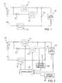
- Fig. 1 shows one example of the circuit which uses the battery pack constituted by serially connecting a plurality of cells of the secondary battery as the DC power supply and in which the relay contact is inserted for each of the positive power supply line and the negative power supply line from the DC power supply.
- the circuit supplies the electric power from battery pack 10 to load circuit 16 such as the inverter circuit.
- load circuit 16 such as the inverter circuit.
- a contact of first main relay 11 is inserted in the power supply line extended from the positive pole of battery pack 10 to one end of load circuit 16.
- an electric connection between battery pack 10 and load circuit 16 can be controlled by an ON (a conductive state)/OFF (an interruption state) control of first main relay 11.
- a contact of second main relay 12 is inserted in the power supply line extended from the negative pole of battery pack 10 to the other end of load circuit 16.
- Capacitor 15 with a large capacity is provided in parallel to load circuit 16.
- capacitor 15 Because of the provision of capacitor 15 here, it is possible that the contacts of main relays 11, 12 are fixed or welded due to a large rush current flowing into capacitor 15 when the contacts of main relays 11, 12 are turned from the interruption state to the conductive state. If welding like this occurs, the relay contact does not transit to the interruption state again, and the function as relay is lost. Of course, depending on the electrical characteristics of load circuit 16 itself, even in a case where there is no capacitor 15 specially provided, the large rush current large enough to weld the relay contact may sometimes flow in the circuit.
- a series circuit comprising resistor 14 and a contact of precharge relay 13 is provided in parallel to the contact of main relay 11 to prevent the welding of the relay contact.
- first, second main relay 12 on the negative side is set to be ON state; and next, the precharge relay 13 is set to be ON state.
- a charging current to capacitor 15 flows via resistor 14, and capacitor 15 is gradually charged.
- first main relay 11 on the positive side is set to be ON state, then, following this, precharge relay 13 is set to be OFF state; and thereby electric power is supplied from battery pack 10 to load circuit 16 via first main relay 11 and second main relay 12 without generating the large rush current.
- the precharge relay is provided, still it is possible that the welding of the contact of the main relay occurs. This is one of the reasons why the main relays are provided for both of the positive and negative sides. In this regard, it is necessary to detect the occurrence of the welding at the contact of the main relay.
- JP, P2000-270561A discloses that in a case where an inverter circuit is used as the load circuit, the welding of the main relay is determined by determining whether or not the output current of the inverter converges to zero after lapse of a prescribed period of time when both of the main relays on the positive side and the negative side are controlled to be off. If the output current of the inverter does not converge to zero after the lapse of the prescribed period of time, this means that the electric power is supplied from the DC power supply side even when the main relay is controlled to be off. Accordingly, it is determined that the welding of the contact of the main relay occurs. However, with this method, it cannot be determined that the welding occurs unless the welding occurs at the contacts of both main relays and also it cannot be detected that the welding occurs at only one of either of the main relays.
- JP 2001-327001 A Another method and apparatus which cannot independently detect the welding of the relay contact are disclosed in JP 2001-327001 A , namely a method for detecting welding of a relay contact in a circuit which comprises: a DC power supply having a first terminal and a second terminal; a load circuit supplied with electric power from the DC power supply by connecting to the first terminal and the second terminal; a first main relay having a contact which is inserted between the first terminal and one end of the load circuit; a second main relay having a contact which is inserted between the second terminal and the other end of the load circuit; and a precharge relay which is provided in parallel to the contact of the first main relay and comprises a series circuit of a resistor and a contact of the precharge relay.
- Japanese Laid-Open Patent Application No. H06-233401 JP, 6-233401, A discloses that the relay having a mechanism for detecting the state of the movable part thereof is used as the main relay; and an abnormality such as welding and the like is detected when the movable part of the relay is at a position corresponding to the conductive state even when the relay is not controlled to be in the conductive state.
- this method it is necessary to provide the main relay with a special mechanism for detecting the state of the movable part thereof; and therefore this method lacks in versatility and also it is necessary to sufficiently pay attention to the reliability of the special mechanism itself.
- JP, P2000-78851A discloses that in a case where the relay for compulsorily discharging the capacitor, namely a discharge relay, is provided in the circuit similar to the circuit as shown in Fig. 1 , the resistor is serially inserted for the contact of the discharge relay in order to prevent the contact of the discharge relay from being welded.
- the method in which the resistor is serially inserted in relation to the relay contact cannot be applied in reality for the main relay as mentioned above in which the contact is directly inserted between the DC power supply and the load circuit.
- JP, P2000-173428A describes a constitution such that a first welding detection circuit using a photo-coupler including a light emitting device connected between the DC power supply side of the contact of one main relay and the load circuit side of the other main relay; and a second welding detection circuit using a photo-coupler including a light emitting device connected between the DC power supply side of the contact of the other main relay and the load circuit side of one main relay, in the same way; are provided; and wherein the welding at the contact of the main relay can be independently detected by using these welding detection circuits.
- this constitution it is necessary to provide as many as two systems of the welding detection circuits which are directly connected to the DC power supply of 200 V or higher; and this results in requiring a high cost for the whole apparatus.
- an object of the present invention is to provide a method for independently detecting, with regard to the welding of the contact of the main relay on each of the positive side or the negative side, whether the welding of the contact occurs on the positive side or the negative side without causing an increase in cost.
- Another object of the present invention is to provide an apparatus for independently detecting, with regard to the welding of the contact of the main relay on each of the positive side or the negative side, whether the welding of the contact occurs on the positive side or the negative side without causing an increase in cost.
- the first object of the present invention is achieved by a method for detecting welding of a relay contact in a circuit which includes: a DC power supply having a first terminal and a second terminal; a load circuit supplied with electric power from the DC power supply by connecting to the first terminal and the second terminal; a first main relay having a contact which is inserted between the first terminal and one end of the load circuit; a second main relay having a contact which is inserted between the second terminal and the other end of the load circuit; and a precharge relay which is provided in parallel to the contact of the first main relay and comprises a series circuit of a resistor and a contact of the precharge relay; wherein the method comprises the step of, when shifting from a normal operation state in which the first main relay and the second main relay are controlled to be on and the precharge relay is controlled to be off to a suspension state in which the first main relay, the second main relay, and the precharge relay are controlled to be off, performing a sequence control to the first main relay, the second main relay and the precharge relay while measuring voltage
- the second object of the present invention is achieved by an apparatus for detecting welding of a relay contact in a circuit which includes: a DC power supply having a first terminal and a second terminal; a load circuit supplied with electric power from the DC power supply by connecting to the first terminal and the second terminal; a first main relay having a contact which is inserted between the first terminal and one end of the load circuit; a second main relay having a contact which is inserted between the second terminal and the other end of the load circuit; and a precharge relay which is provided in parallel to the contact of the first main relay and comprises a series circuit of a resistor and a contact of the precharge relay; wherein the apparatus includes: a voltage detection means for detecting voltage across both ends of the load circuit; an instruction input means for receiving an instruction for shifting from a normal operation state in which the first main relay and the second main relay are controlled to be on and the precharge relay is controlled to be off to a suspension state in which the first main relay, the second main relay and the precharge relay are controlled to be off; and a
- a capacitor for connecting both ends of the load circuit is typically provided in the circuit as described above.
- sequence control used in the present invention, various kinds of the sequence controls can be considered. However, considering that it is desirable that the number of steps to be taken is small; that the welding of the contact of the first main relay and the second main relay can be independently and securely detected; and that it can be guaranteed that the contact of each of the relays is a state of interruption and non-welding during in the suspension state when it is determined that the contact is in a normal state throughout the sequence it is preferable that the sequence control comprises: a first step of controlling the first main relay to be off; a second step of controlling the precharge relay to be on after the first step; a third step of controlling the second main relay to be off after the second step; and a fourth step of controlling the precharge relay to be off after the third step and to shift to the suspension state.
- the contact of the first main relay is welded if the voltage across both ends of the load circuit does not drop at the first step; and that the contact of the second main relay is welded if the voltage across both ends of the load circuit does not drop at the third step.
- Fig. 2 is a view showing one example of a circuit to which a detection method according to the present invention applies.
- the circuit is intended for application to an electric automobile or a hybrid electric automobile, and has the same configuration as the circuit shown in Fig. 1 .
- Fig. 2 differs from Fig. 1 in that control circuit 21 for controlling load circuit 16 and for performing an ON/OFF control of first main relay 11, second main relay 12 and precharge relay 13; voltage measuring unit 22 for measuring and outputting to control circuit 21 the voltage across both ends of capacitor 15, that is, the voltage across both ends of load circuit 16; and ignition key switch 23 interlocked with an ignition key in the electric automobile or the hybrid electric automobile are clearly shown.
- Load circuit 16 is, typically, an inverter circuit.
- control circuit 21 itself does not operate by the power from battery pack 10 but by the power from an auxiliary power supply (not shown) such as an accumulator battery of a low voltage (for example, 12 V) which is provided separately.
- an auxiliary power supply not shown
- an accumulator battery of a low voltage for example, 12 V
- control circuit 21 for controlling each of the relays 11 to 13 and load circuit 16 which is the inverter circuit and that ignition key switch 23 are connected to control circuit 21 is self-evident to the person skilled in the art.
- the inverter circuit (load circuit 16) is provided with a measurement circuit for measuring an input voltage thereto, the measurement circuit can be used for voltage control unit 22.
- the configuration of the circuit as shown in Fig. 2 itself is a common configuration for an on-vehicle circuit.
- the present invention is characterized in that a common circuit like this is employed therein and that the welding of the contact of each of the main relays 11, 12 is individually and separately detected by a control sequence by means of a software control over the relay.
- Fig. 3 shows the sequence for detection of the welding in this case.
- control circuit 21 when shifting from a normal operation state to a suspension state, control circuit 21 performs the sequence control of the ON/OFF control of each of relays 11 to 13, and the welding of the contacts of each of relays 11 to 13 is detected.
- the normal operation refers to the state in which, in the case of the circuit for the electric automobile and the hybrid automobile, for example, the power is supplied from battery pack 10 to load circuit 16 so that a motor is driven.
- the suspension state refers to the state in which the supply of power to load circuit 16 is suspended.
- each of the contacts of first main relay 11 and second main relay 12 are controlled to be on (set to a conductive state), and the contact of precharge relay 13 is controlled to be off (set to an interruption state).
- capacitor 15 is charged up to the level of the voltage of battery pack 10. If the ignition key of the vehicle is turned off, it is detected by ignition key switch 23 that the ignition key is turned off and this is notified to control circuit 21. Then, control circuit 21 starts the sequence for detecting the welding and for shifting to the suspension state. First, in phase 2, control circuit 21 controls the contact of first main relay 11 on the positive side to be off.
- the voltage across both ends of capacitor 15 in a case where first main relay 11 is welded is substantially equal to a terminal voltage of battery pack 10; on the other hand, in a case where the contact of first main relay 11 is normal and the contact of precharge relay 13 is welded, the voltage across both end of capacitor 15 become the values obtained by dividing the voltage of the terminal voltage of battery pack 10 by a voltage division circuit constituted by resistor 14 and load circuit 16. Therefore, depending on the value of resistor 14, it is also possible to isolate the phenomenon of welding of the contact between first main relay 11 and precharge relay 13 by determining at which value the voltage across both ends of capacitor 15 converges.
- phase 3 which is continued from phase 2 as described above, the contact of precharge relay 13 is controlled to be on.
- second main relay 12 since second main relay 12 is still in the on state, capacitor 15 is charged via precharge relay 13, and the voltage across both ends of capacitor 15 is raised.
- the contact of second main relay 12 on the negative side is controlled to be off. If the contact of each of the relays is normal, the electric charge stored in capacitor 15 is discharged via load circuit 16; and the voltage across both ends of the capacitor 15 drops toward zero.
- the voltage across both ends of capacitor 15, which is measured by voltage measurement unit 22, does not drop, it means that capacitor 15 is continuously supplied with electric power from battery pack 10; and it can be determined that the contact of second main relay 12 is fixed by welding.
- phase 5 which is the suspension state.
- the power supply from the auxiliary power supply to control circuit 21 may also be suspended after the shift to phase 5.
- control circuit 21 controls second main relay 12 and precharge relay 13 to be on, and the precharge to capacitor 15 is started.
- first main relay 11 is also controlled to be on in phase 7.
- precharge relay 13 is controlled to be off and the sequence completely shifts to the normal operation state (phase 1).
- control circuit 21 in order to detect the welding of the contact will be explained with reference to the flow chart of Fig. 4 .
- first main relay 11 and second main relay 12 are controlled to be on; and precharge relay 13 is controlled to be off. This is an initial state of the processing to be described below.
- step 51 it is determined whether or not the ignition key is turned off and the processing waits until the ignition key is turned off.
- first main relay 11 is controlled to be off in step 52.
- step 53 it is determined whether or not the voltage measured by voltage measurement unit 22 drops. If it is determined that the voltage drops, the processing shifts to step 55 as it is; and if it is determined that the voltage does not drop, it is determined in step 54 that there occurs welding of the contact of first main relay 11 (or precharge relay 13) and a warning is outputted.
- precharge relay 55 is controlled to be on.
- second main relay 12 is controlled to be off in step 56.
- step 57 it is determined whether or not the voltage measured by voltage measurement unit 22 drops. If it is determined that the voltage drops, the processing shifts to step 59 as it is; and if it is determined that the voltage does not drop, it is determined in step 58 that there occurs welding of the contact of second main relay 12 and the warning is outputted. In addition, if it is determined that the voltage does not drop, an error code is recorded within a nonvolatile memory region in control circuit 21. In step 59, precharge relay 59 is controlled to be off and is shifted to the suspension state.
- the output of the warning in steps 54 and 58 includes, for example, a display of the warning to the operator, the recording of the error codes in the nonvolatile memory region in control circuit 21, and the like.
- the warning is displayed to the-operator and the like again at the time of a next startup, for example, at the time when the ignition key is set to be on for the next time
Landscapes
- Physics & Mathematics (AREA)
- General Physics & Mathematics (AREA)
- Keying Circuit Devices (AREA)
- Electric Propulsion And Braking For Vehicles (AREA)
- Testing Electric Properties And Detecting Electric Faults (AREA)
Claims (15)
- Verfahren zum Erkennen des Schweißens eines Relaiskontakts in einer Schaltung, die umfasst: eine Gleichstromversorgung (10) mit einem ersten Anschluss und einem zweiten Anschluss; einen Lastkreis (16), der von der Gleichstromversorgung (10) mit elektrischem Strom versorgt wird, indem der erste Anschluss mit dem zweiten Anschluss verbunden wird; ein erstes Hauptrelais (11) mit einem Kontakt, der zwischen dem ersten Anschluss und einem Ende des Lastkreises (16) eingefügt ist; ein zweites Hauptrelais (12) mit einem Kontakt, der zwischen dem zweiten Anschluss und dem anderen Ende des Lastkreises (16) eingefügt ist; und ein Vorladungsrelais (13), das parallel zu dem Kontakt des ersten Hauptrelais (11) vorgesehen ist und eine Reihenschaltung eines Widerstands (14) und eines Kontakts des Vorladungsrelais (13) umfasst, wobei das Verfahren den folgenden Schritt umfasst:wenn aus einem normalen Betriebszustand, in dem das erste Hauptrelais (11) und das zweite Hauptrelais (12) so gesteuert werden, dass sie an sind, und das Vorladungsrelais (13) so gesteuert wird, dass es aus ist, in einen Schwebezustand geschaltet wird, in dem das erste Hauptrelais (11), das zweite Hauptrelais (12) und das Vorladungsrelais (13) so gesteuert werden, dass sie aus sind, ist es gekennzeichnet durch Durchführen einer Sequenzsteuerung an dem ersten Hauptrelais (11), dem zweiten Hauptrelais (12) und dem Vorladungsrelais (13), während die Spannung über beide Enden des Lastkreises (16) gemessen wird, um das Schweißen des Relaiskontakts individuell und getrennt zu erkennen.
- Verfahren nach Anspruch 1, wobei die Schaltung für ein Fahrzeug mit einem Zündschlüsselschalter (23) vorgesehen ist und die Sequenzsteuerung ausgelöst wird, wenn erkannt wird, dass der Zündschlüsselschalter (23) abgeschaltet wird.
- Verfahren nach Anspruch 1, wobei die Sequenzsteuerung umfasst: einen ersten Schritt (52) zum Steuern, dass das erste Hauptrelais (11) aus ist; einen zweiten Schritt (55) zum Steuern, dass das Vorladungsrelais (13) nach dem ersten Schritt (52) an ist; einen dritten Schritt (56) zum Steuern, dass das zweite Hauptrelais (12) nach dem zweiten Schritt (55) aus ist; und einen vierten Schritt (59) zum Steuern, dass das Vorladungsrelais (13) nach dem dritten Schritt (56) aus ist, um in den Schwebestatus umzuschalten.
- Verfahren nach Anspruch 3, wobei, wenn die Spannung über beide Enden des Lastkreises (16) beim ersten Schritt (52) nicht abfällt, bestimmt wird, dass der Kontakt des ersten Hauptrelais (11) geschweißt ist.
- Verfahren nach Anspruch 4, wobei, wenn die Spannung über beide Enden des Lastkreises (16) beim dritten Schritt (56) nicht abfällt, bestimmt wird, dass der Kontakt des zweiten Hauptrelais (12) geschweißt ist.
- Verfahren nach Anspruch 1, wobei die Schaltung mit einem Kondensator (15) zum Verbinden beider Enden des Lastkreises (16) versehen ist.
- Verfahren nach Anspruch 6, wobei die Schaltung für ein Fahrzeug mit einem Zündschlüsselschalter (23) vorgesehen ist; und wobei die Sequenzsteuerung ausgelöst wird, wenn erkannt wird, dass der Zündschlüsselschalter (23) ausgeschaltet wird.
- Verfahren nach Anspruch 6, wobei die Sequenzsteuerung umfasst: einen ersten Schritt (52) zum Steuern, dass das erste Hauptrelais (11) aus ist; einen zweiten Schritt (55) zum Steuern, dass das Vorladungsrelais (13) nach dem ersten Schritt (52) an ist; einen dritten Schritt (56) zum Steuern, dass das zweite Hauptrelais (12) nach dem zweiten Schritt (55) aus ist; und einen vierten Schritt (59) zum Steuern, dass das Vorladungsrelais (13) nach dem dritten Schritt (56) aus ist, um in den Schwebestatus umzuschalten.
- Verfahren nach Anspruch 8, wobei, wenn die Spannung über beide Enden des Lastkreises (16) beim ersten Schritt (52) nicht abfällt, bestimmt wird, dass der Kontakt des ersten Hauptrelais (11) geschweißt ist.
- Verfahren nach Anspruch 8, wobei, wenn die Spannung über beide Enden des Lastkreises (16) beim dritten Schritt (56) nicht abfällt, bestimmt wird, dass der Kontakt des zweiten Hauptrelais (12) geschweißt ist.
- Verfahren nach Anspruch 1, wobei die Gleichstromversorgung (10) eine Batteriepackung ist.
- Vorrichtung zum Erkennen von Schweißen eines Relaiskontakts in einer Schaltung, die umfasst: eine Gleichstromversorgung (10) mit einem ersten Anschluss und einem zweiten Anschluss; einen Lastkreis (16), der von der Gleichstromversorgung (10) mit elektrischem Strom versorgt wird, indem der erste Anschluss mit dem zweiten Anschluss verbunden wird; ein erstes Hauptrelais (11) mit einem Kontakt, der zwischen dem ersten Anschluss und einem Ende des Lastkreises (16) eingefügt ist; ein zweites Hauptrelais (12) mit einem Kontakt, der zwischen dem zweiten Anschluss und dem anderen Ende des Lastkreises (16) eingefügt ist; und ein Vorladungsrelais (13), das parallel zu dem Kontakt des ersten Hauptrelais (13) vorgesehen ist und eine Reihenschaltung eines Widerstands (14) und eines Kontakts des Vorladungsrelais (13) umfasst,
wobei die Vorrichtung umfasst:ein Spannungserkennungsmittel (22) zum Erkennen einer Spannung über beide Enden des Lastkreises (16);ein Anweisungseingabemittel (23) zum Empfangen einer Anweisung zum Umschalten aus einem normalen Betriebszustand, in dem das erste Hauptrelais (11) und das zweite Hauptrelais (12) so gesteuert werden, dass sie an sind, und das Vorladungsrelais (13) so gesteuert wird, dass es aus ist, in einen Schwebezustand, in dem das erste Hauptrelais (11), das zweite Hauptrelais (12) und das Vorladungsrelais (13) so gesteuert werden, dass sie aus sind; undein Steuermittel (21);dadurch gekennzeichnet, dass das Steuermittel (21) eine Sequenzsteuerung an dem ersten Hauptrelais (11), dem zweiten Hauptrelais (12) und dem Vorladungsrelais (13) durchführt, wenn die Anweisung eingegeben wird, und das Schweißen des Relaiskontakts individuell und getrennt aus einer Abweichung der durch das Spannungserkennungsmittel (22) erkannten Spannung erkennt, die in Übereinstimmung mit dem Ablauf der Sequenzsteuerung auftritt. - Vorrichtung nach Anspruch 12, wobei die Sequenzsteuerung umfasst: einen ersten Schritt (52) zum Steuern, dass das erste Hauptrelais (11) aus ist; einen zweiten Schritt (55) zum Steuern, dass das Vorladungsrelais (13) nach dem ersten Schritt (52) an ist; einen dritten Schritt (56) zum Steuern, dass das zweite Hauptrelais (12) nach dem zweiten Schritt (55) aus ist; und einen vierten Schritt (59) zum Steuern, dass das Vorladungsrelais (13) nach dem dritten Schritt (56) aus ist, um in den Schwebestatus umzuschalten; wobei
das Steuermittel bestimmt, dass der Kontakt des ersten Hauptrelais (11) geschweißt ist, und eine Warnung liefert, wenn die Spannung über beide Enden des Lastkreises (16) beim ersten Schritt (52) nicht abfällt; und bestimmt, dass der Kontakt des zweiten Hauptrelais (12) geschweißt ist, und eine Warnung liefert, wenn die Spannung über beide Enden des Lastkreises (16) beim dritten Schritt (56) nicht abfällt. - Vorrichtung nach Anspruch 12, wobei die Schaltung mit einem Kondensator (15) zum Verbinden beider Enden des Lastkreises (16) versehen ist.
- Vorrichtung nach Anspruch 14, wobei die Sequenzsteuerung umfasst: einen ersten Schritt (52) zum Steuern, dass das erste Hauptrelais (11) aus ist; einen zweiten Schritt (55) zum Steuern, dass das Vorladungsrelais (13) nach dem ersten Schritt (52) an ist; einen dritten Schritt (56) zum Steuern, dass das zweite Hauptrelais (12) nach dem zweiten Schritt (55) aus ist; und einen vierten Schritt (59) zum Steuern, dass das Vorladungsrelais (13) nach dem dritten Schritt (56) aus ist, um in den Schwebestatus umzuschalten; wobei
das Steuermittel bestimmt, dass der Kontakt des ersten Hauptrelais (11) geschweißt ist, und eine Warnung liefert, wenn die Spannung über beide Enden des Lastkreises (16) beim ersten Schritt (52) nicht abfällt; und bestimmt, dass der Kontakt des zweiten Hauptrelais (12) geschweißt ist, und eine Warnung liefert, wenn die Spannung über beide Enden des Lastkreises (16) beim dritten Schritt (56) nicht abfällt.
Applications Claiming Priority (3)
| Application Number | Priority Date | Filing Date | Title |
|---|---|---|---|
| JP2003095045 | 2003-03-31 | ||
| JP2003095045 | 2003-03-31 | ||
| PCT/JP2004/004410 WO2004088696A1 (ja) | 2003-03-31 | 2004-03-29 | リレー接点の溶着の検出方法及び装置 |
Publications (4)
| Publication Number | Publication Date |
|---|---|
| EP1610355A1 EP1610355A1 (de) | 2005-12-28 |
| EP1610355A8 EP1610355A8 (de) | 2006-03-15 |
| EP1610355A4 EP1610355A4 (de) | 2009-01-28 |
| EP1610355B1 true EP1610355B1 (de) | 2012-12-05 |
Family
ID=33127425
Family Applications (1)
| Application Number | Title | Priority Date | Filing Date |
|---|---|---|---|
| EP04724176A Expired - Lifetime EP1610355B1 (de) | 2003-03-31 | 2004-03-29 | Relaiskontaktschweissdetektionsverfahren und -vorrichtung |
Country Status (6)
| Country | Link |
|---|---|
| US (1) | US7368829B2 (de) |
| EP (1) | EP1610355B1 (de) |
| JP (1) | JP4572168B2 (de) |
| KR (1) | KR100750463B1 (de) |
| CN (1) | CN100454466C (de) |
| WO (1) | WO2004088696A1 (de) |
Families Citing this family (114)
| Publication number | Priority date | Publication date | Assignee | Title |
|---|---|---|---|---|
| JPWO2005081386A1 (ja) * | 2004-02-24 | 2007-10-25 | 株式会社デンソー | リレー溶着防止装置およびモータ駆動装置 |
| JP4539431B2 (ja) * | 2005-05-11 | 2010-09-08 | トヨタ自動車株式会社 | 電源制御装置 |
| JP4529851B2 (ja) * | 2005-09-20 | 2010-08-25 | トヨタ自動車株式会社 | 電源回路の異常検知装置 |
| JP4233571B2 (ja) * | 2006-01-04 | 2009-03-04 | ファナック株式会社 | ロボット制御装置 |
| JP4749190B2 (ja) * | 2006-03-24 | 2011-08-17 | 三洋電機株式会社 | 車両用の電源装置とこの電源装置のコンタクターの溶着を判別する溶着検出方法 |
| GB0618666D0 (en) * | 2006-09-22 | 2006-11-01 | Eja Ltd | Safety switch |
| JP4760723B2 (ja) | 2006-11-20 | 2011-08-31 | トヨタ自動車株式会社 | 電源回路の制御装置 |
| JP4699399B2 (ja) * | 2007-02-06 | 2011-06-08 | プライムアースEvエナジー株式会社 | 電源装置 |
| JP4697180B2 (ja) * | 2007-04-25 | 2011-06-08 | トヨタ自動車株式会社 | 電源制御装置、電源装置の制御方法、および電源装置の制御方法をコンピュータに実行させるためのプログラムを記録したコンピュータ読取可能な記録媒体 |
| JP2008301612A (ja) * | 2007-05-31 | 2008-12-11 | Sanyo Electric Co Ltd | 車両用の電源装置とこの電源装置のコンタクター溶着検出方法 |
| AU2008280932B8 (en) * | 2007-07-24 | 2011-02-24 | Panasonic Electric Works Co., Ltd. | Charging monitor |
| JP5274046B2 (ja) * | 2008-02-21 | 2013-08-28 | 三洋電機株式会社 | 車両用の電源装置 |
| US7966110B2 (en) * | 2008-03-05 | 2011-06-21 | GM Global Technology Operations LLC | High-voltage vehicle fault detection method and apparatus |
| JP4720896B2 (ja) * | 2008-10-08 | 2011-07-13 | 株式会社デンソー | 電源回路の異常診断装置、及び電源回路 |
| JP5205356B2 (ja) * | 2009-10-09 | 2013-06-05 | 日立オートモティブシステムズ株式会社 | 電源装置とコンタクタ溶着判定方法 |
| DE102009047104A1 (de) * | 2009-11-25 | 2011-05-26 | Robert Bosch Gmbh | Diagnose von Relais in einer Batterie |
| CN101841177B (zh) * | 2010-04-23 | 2012-10-24 | 北汽福田汽车股份有限公司 | 一种保护电动汽车预充电电路的方法与系统 |
| JP5460455B2 (ja) * | 2010-05-06 | 2014-04-02 | キヤノン株式会社 | 画像形成装置 |
| JP5393640B2 (ja) * | 2010-11-25 | 2014-01-22 | 三菱自動車工業株式会社 | 電動車両の充電制御装置 |
| US8706345B2 (en) * | 2010-12-09 | 2014-04-22 | Honda Motor Co., Ltd. | Starter relay structure for auto-starting |
| CN102540064A (zh) * | 2010-12-29 | 2012-07-04 | 比亚迪股份有限公司 | 一种高压放电控制回路中接触器烧结检测方法 |
| JP5011443B1 (ja) * | 2011-03-30 | 2012-08-29 | パナソニック株式会社 | リレー溶着検出回路及び電力供給システム |
| CN102723689A (zh) * | 2011-03-30 | 2012-10-10 | 比亚迪股份有限公司 | 电源自动切断保护电路及其控制方法 |
| JP5520250B2 (ja) * | 2011-04-05 | 2014-06-11 | 富士重工業株式会社 | ハイブリッド車両の制御システム |
| JP5461478B2 (ja) | 2011-06-15 | 2014-04-02 | 富士重工業株式会社 | 充電システムおよび電動車両 |
| US8941264B2 (en) * | 2011-06-20 | 2015-01-27 | Bae Systems Information And Electronic Systems Integration Inc. | Apparatus for bi-directional power switching in low voltage vehicle power distribution systems |
| JP6001242B2 (ja) * | 2011-06-27 | 2016-10-05 | 川崎重工業株式会社 | 故障処理システム |
| CN102343876B (zh) * | 2011-07-18 | 2013-10-30 | 上海中科深江电动车辆有限公司 | 电动车辆高压电控制电路结构 |
| DE102011108408A1 (de) * | 2011-07-23 | 2013-01-24 | Volkswagen Aktiengesellschaft | Verfahren und Testsystem zum Test einer Schützanordnung für ein Fahrzeug |
| CN102426319A (zh) * | 2011-09-16 | 2012-04-25 | 天津市松正电动汽车技术股份有限公司 | 直流供电系统接触器粘连检测装置、方法及电动车辆 |
| US9434261B2 (en) | 2011-10-17 | 2016-09-06 | Robert Bosch Gmbh | Welded contactor checking systems and methods |
| JP5895171B2 (ja) * | 2011-10-31 | 2016-03-30 | パナソニックIpマネジメント株式会社 | 有極型電磁リレー |
| KR20150127765A (ko) * | 2012-02-09 | 2015-11-18 | 에스케이이노베이션 주식회사 | 고전압 배터리 시스템 |
| JP2013169087A (ja) * | 2012-02-15 | 2013-08-29 | Hitachi Vehicle Energy Ltd | 電源装置の異常検出装置およびこれを備えた回転電機の電動駆動装置 |
| US8792222B2 (en) * | 2012-02-29 | 2014-07-29 | Lg Chem, Ltd. | Driver circuit for an electric vehicle and a diagnostic method |
| JP2013206643A (ja) * | 2012-03-28 | 2013-10-07 | Hitachi Ltd | 電池システムのリレー溶着検知装置、及びこれを用いた電池システム |
| JP5831760B2 (ja) * | 2012-04-05 | 2015-12-09 | 株式会社デンソー | 電源制御システムの異常診断装置 |
| KR101776341B1 (ko) * | 2012-05-11 | 2017-09-07 | 현대자동차주식회사 | 친환경자동차의 메인릴레이 고장진단 방법 |
| US8861161B2 (en) * | 2012-06-29 | 2014-10-14 | Lg Chem, Ltd. | Driver circuit for an electric vehicle and a diagnostic method for determining when first and second voltage drivers are shorted to a high voltage |
| US11179794B2 (en) * | 2012-06-29 | 2021-11-23 | Illinois Tool Works Inc | Welding system utilizing a distributed power bus |
| KR101953121B1 (ko) | 2012-11-14 | 2019-02-28 | 에스케이이노베이션 주식회사 | 배터리 시스템의 릴레이 융착 검출 장치 및 방법 |
| CN103036206A (zh) * | 2012-11-29 | 2013-04-10 | 潍柴动力股份有限公司 | 一种电机控制器预充线路故障的检测方法及装置 |
| US10464507B2 (en) * | 2013-03-07 | 2019-11-05 | Samsung Sdi Co., Ltd. | Battery management system and switching method thereof |
| US9897656B2 (en) | 2013-05-16 | 2018-02-20 | Carrier Corporation | Method for sensing welded contacts on a switching device |
| JP5751282B2 (ja) * | 2013-05-29 | 2015-07-22 | 株式会社デンソー | 制御装置 |
| DE102013213286A1 (de) * | 2013-07-08 | 2015-01-08 | Robert Bosch Gmbh | Verfahren und Vorrichtung zum Betreiben einer Energiespeichervorrichtung |
| US9726725B2 (en) * | 2013-08-02 | 2017-08-08 | Jtekt Corporation | Power circuit abnormality detection method |
| JP6185337B2 (ja) | 2013-08-26 | 2017-08-23 | 株式会社トランストロン | リレー回路の診断装置及び診断方法 |
| US9871460B2 (en) * | 2013-09-30 | 2018-01-16 | Panasonic Intellectual Property Management Co., Ltd. | Power source switching device and storage battery system |
| FR3011673B1 (fr) | 2013-10-08 | 2015-12-11 | Schneider Electric Ind Sas | Dispositif de commutation et procede de detection d'un defaut d'un tel dispositif de commutation |
| JP5605486B2 (ja) * | 2013-10-11 | 2014-10-15 | 三菱自動車工業株式会社 | 電動車両の充電制御装置 |
| JP5867483B2 (ja) * | 2013-11-08 | 2016-02-24 | トヨタ自動車株式会社 | 蓄電システム |
| CN104656629B (zh) * | 2013-11-18 | 2018-01-23 | 比亚迪股份有限公司 | 用于接触器的烧结检测装置和方法 |
| JP6315545B2 (ja) * | 2013-11-20 | 2018-04-25 | 住友重機械工業株式会社 | ショベル |
| US9466448B2 (en) | 2014-03-24 | 2016-10-11 | Ford Global Technologies, Llc | HV relay sticking control system and method |
| JP5937635B2 (ja) * | 2014-03-28 | 2016-06-22 | ファナック株式会社 | 電磁接触器の溶着検出機能を有するモータ駆動装置 |
| KR101551088B1 (ko) * | 2014-05-09 | 2015-09-07 | 현대자동차주식회사 | 배터리 승온 시스템 및 릴레이 고장 검출 장치 및 그 방법 |
| CN103995211A (zh) * | 2014-05-30 | 2014-08-20 | 长城汽车股份有限公司 | 车用高压系统的检测方法及系统 |
| KR102210282B1 (ko) * | 2014-05-30 | 2021-02-01 | 삼성전자주식회사 | 릴레이 상태 검출 방법 및 장치 |
| CN104827910B (zh) * | 2014-07-14 | 2017-07-11 | 北汽福田汽车股份有限公司 | 电动汽车的高压系统控制方法、系统及具有其的车辆 |
| KR101821008B1 (ko) * | 2014-09-15 | 2018-03-08 | 엘에스산전 주식회사 | 전기 자동차 충전 장치 |
| JP2016073015A (ja) * | 2014-09-26 | 2016-05-09 | キヤノン株式会社 | 電力供給装置及び画像形成装置 |
| JP6417892B2 (ja) * | 2014-11-21 | 2018-11-07 | 三菱自動車工業株式会社 | コンタクタ故障判定方法およびコンタクタ故障判定装置 |
| JP6444749B2 (ja) * | 2015-01-27 | 2018-12-26 | 株式会社椿本チエイン | スイッチ装置及びスイッチの短絡判定方法 |
| US9506992B2 (en) * | 2015-03-25 | 2016-11-29 | GM Global Technology Operations LLC | Systems and methods for detecting high-voltage contactor state of health |
| US9916940B2 (en) * | 2015-09-04 | 2018-03-13 | Te Connectivity Corporation | Power controller having adaptive control of a switching circuit |
| KR101679985B1 (ko) | 2015-10-16 | 2016-12-06 | 현대자동차주식회사 | 릴레이 융착 검출 방법 |
| KR101673822B1 (ko) * | 2015-11-18 | 2016-11-07 | 현대자동차주식회사 | 친환경 차량의 릴레이 융착 검출 장치 및 그 방법 |
| JP6547602B2 (ja) * | 2015-11-24 | 2019-07-24 | トヨタ自動車株式会社 | 燃料電池システム |
| JP6477512B2 (ja) * | 2016-01-19 | 2019-03-06 | トヨタ自動車株式会社 | 燃料電池システム |
| EP3276775B1 (de) | 2016-07-27 | 2018-11-28 | Samsung SDI Co., Ltd. | Batteriesystem für ein hybridfahrzeug |
| JP6677129B2 (ja) * | 2016-08-31 | 2020-04-08 | トヨタ自動車株式会社 | 燃料電池システム |
| CN106449274B (zh) * | 2016-10-31 | 2018-08-21 | 国网山东省电力公司莱芜供电公司 | 一种带自诊断报警功能的继电器输出装置及其诊断报警方法 |
| CN108072822B (zh) * | 2016-11-07 | 2020-05-22 | 株洲中车时代电气股份有限公司 | 一种传动系统主电路接触器卡分故障诊断方法 |
| FR3058795B1 (fr) * | 2016-11-14 | 2021-01-15 | Peugeot Citroen Automobiles Sa | Procede de detection de collage d’un de deux relais disposes en serie dans une ligne de commande d’un demarreur de vehicule automobile |
| KR102058198B1 (ko) * | 2016-12-12 | 2019-12-20 | 주식회사 엘지화학 | 상시 전원 공급을 위한 병렬 회로를 이용하여 배터리의 릴레이의 고장을 진단하는 장치 및 방법 |
| US11056303B2 (en) * | 2016-12-28 | 2021-07-06 | Nissan Motor Co., Ltd. | Relay device |
| CN114325412B (zh) * | 2017-03-20 | 2024-12-06 | 深圳引望智能技术有限公司 | 一种检测电路、方法和装置 |
| KR102322753B1 (ko) * | 2017-04-13 | 2021-11-05 | 에스케이이노베이션 주식회사 | 차량용 릴레이의 고장 진단 시스템 |
| JP2018196285A (ja) * | 2017-05-19 | 2018-12-06 | パナソニックIpマネジメント株式会社 | 電源制御装置、溶着検出方法およびリレー溶着検出装置 |
| JP6885559B2 (ja) * | 2017-06-12 | 2021-06-16 | 株式会社サムソン | リレーのセルフチェックを行う制御装置 |
| CN107579561B (zh) * | 2017-09-04 | 2021-03-19 | 佛山市索尔电子实业有限公司 | 一种具有mppt功能的太阳能充电控制电路 |
| KR102204983B1 (ko) | 2017-09-25 | 2021-01-18 | 주식회사 엘지화학 | 배터리 관리 장치와 이를 포함하는 배터리 팩 및 자동차 |
| WO2019077958A1 (ja) * | 2017-10-17 | 2019-04-25 | 株式会社村田製作所 | 電源装置、電力制御装置、電源装置のリレー判定方法 |
| KR102256094B1 (ko) * | 2017-11-28 | 2021-05-25 | 주식회사 엘지에너지솔루션 | 배터리 팩 |
| KR102256095B1 (ko) | 2017-11-29 | 2021-05-25 | 주식회사 엘지에너지솔루션 | 배터리 팩 |
| KR102256100B1 (ko) | 2017-11-29 | 2021-05-25 | 주식회사 엘지에너지솔루션 | 배터리 팩 |
| KR102256099B1 (ko) | 2017-11-29 | 2021-05-25 | 주식회사 엘지에너지솔루션 | 배터리 팩 |
| KR102256101B1 (ko) * | 2018-01-30 | 2021-05-25 | 주식회사 엘지에너지솔루션 | 프리차지 저항 보호 장치 |
| JP7060435B2 (ja) | 2018-04-19 | 2022-04-26 | Fdk株式会社 | 故障検知機能付き充電器、及び故障検知方法 |
| CN109398152A (zh) * | 2018-11-01 | 2019-03-01 | 芜湖奇达动力电池系统有限公司 | 插电式混合动力汽车电池系统高压预充控制方法 |
| KR102719635B1 (ko) * | 2018-12-10 | 2024-10-21 | 현대자동차주식회사 | 차량의 실내 온도 차등 제어방법 및 이의 시스템 |
| JP7096778B2 (ja) * | 2019-02-08 | 2022-07-06 | 株式会社Subaru | スイッチシステム |
| US11130420B2 (en) | 2019-04-05 | 2021-09-28 | Ford Global Technologies, Llc | System and method for charge contactor weld check |
| CN110262352B (zh) * | 2019-07-03 | 2021-03-26 | 中车株洲电力机车有限公司 | 微型断路器状态的判断方法及装置 |
| US11592485B2 (en) * | 2019-10-04 | 2023-02-28 | Farasis Energy (Ganzhou) Co., Ltd. | Methods and apparatus for contactor weld detection in a vehicle |
| JP7283415B2 (ja) * | 2020-02-19 | 2023-05-30 | トヨタ自動車株式会社 | 電源回路の制御装置 |
| JP7365962B2 (ja) | 2020-05-12 | 2023-10-20 | 株式会社クボタ | バッテリユニット |
| JP7246837B2 (ja) * | 2020-05-19 | 2023-03-28 | 矢崎総業株式会社 | 充電制御装置 |
| KR102729158B1 (ko) * | 2020-06-08 | 2024-11-12 | 주식회사 엘지에너지솔루션 | 릴레이 진단 장치, 릴레이 진단 방법, 배터리 시스템 및 전기 차량 |
| KR102876226B1 (ko) * | 2020-11-27 | 2025-10-27 | 주식회사 엘지에너지솔루션 | 릴레이 상태 관리 장치 및 그것의 동작 방법 |
| WO2022208517A1 (en) * | 2021-03-29 | 2022-10-06 | Tvs Motor Company Limited | Method for pre-charging an ignition capacitor |
| JP7767816B2 (ja) | 2021-10-01 | 2025-11-12 | マツダ株式会社 | 車両のコンタクタ故障判定装置 |
| JP7767815B2 (ja) | 2021-10-01 | 2025-11-12 | マツダ株式会社 | 車両のコンタクタ故障判定装置 |
| CN115993526A (zh) * | 2021-10-20 | 2023-04-21 | 李尔公司 | 用于检测继电器状态的电路和方法 |
| CN114300307B (zh) * | 2021-11-30 | 2024-01-02 | 厦门科华数能科技有限公司 | 一种储能逆变器中旁路继电器单元的粘死检测方法和储能逆变器 |
| JPWO2023176228A1 (de) * | 2022-03-18 | 2023-09-21 | ||
| JP7392756B2 (ja) | 2022-03-24 | 2023-12-06 | いすゞ自動車株式会社 | リレーの溶着診断装置 |
| CN114977896B (zh) * | 2022-05-24 | 2026-02-13 | 深圳市华成工业控制股份有限公司 | 一种六轴驱控一体控制器 |
| WO2024092495A1 (zh) * | 2022-11-01 | 2024-05-10 | 宁德时代新能源科技股份有限公司 | 开关模块的状态检测方法、电路、设备及存储介质 |
| FR3144869A1 (fr) * | 2023-01-06 | 2024-07-12 | Psa Automobiles Sa | Vehicule automobile comprenant un systeme de diagnostique de relai point milieu, procede et programme sur la base d’un tel vehicule |
| US20240317084A1 (en) * | 2023-03-20 | 2024-09-26 | Ford Global Technologies, Llc | Direct current fast charge monitoring and control |
| TW202536454A (zh) * | 2024-02-08 | 2025-09-16 | 日商松下知識產權經營股份有限公司 | 故障診斷裝置及電池包 |
| CN118608235B (zh) * | 2024-05-31 | 2025-02-11 | 中合数字科技(广东)有限公司 | 一种复杂报价订单的处理方法及系统 |
Family Cites Families (12)
| Publication number | Priority date | Publication date | Assignee | Title |
|---|---|---|---|---|
| JPH06233401A (ja) | 1993-02-02 | 1994-08-19 | Toyota Motor Corp | 電気自動車のインバータ入力リレー装置 |
| US5369540A (en) * | 1993-02-11 | 1994-11-29 | General Electric Company | Electric vehicle drive train with contactor protection |
| JP2000078851A (ja) | 1998-08-28 | 2000-03-14 | Nissan Motor Co Ltd | Dcリンクコンデンサーの強制放電装置 |
| JP2000134707A (ja) * | 1998-10-26 | 2000-05-12 | Toyota Motor Corp | 電源制御装置 |
| JP2000173428A (ja) | 1998-12-01 | 2000-06-23 | Sanyo Electric Co Ltd | 電気自動車のメインリレー溶着検出装置 |
| JP3536716B2 (ja) | 1999-03-19 | 2004-06-14 | トヨタ自動車株式会社 | リレーの溶着検出装置 |
| JP2000278802A (ja) * | 1999-03-23 | 2000-10-06 | Toyota Motor Corp | 不具合判定システム |
| KR100432285B1 (ko) * | 2000-02-18 | 2004-05-22 | 산요덴키가부시키가이샤 | 전동 차량의 릴레이 용착 검출 장치 |
| JP2001327001A (ja) * | 2000-05-11 | 2001-11-22 | Toyota Motor Corp | ハイブリッド車両におけるシステムリレーの診断装置およびその方法 |
| JP3511593B2 (ja) * | 2000-11-10 | 2004-03-29 | 三菱電機株式会社 | 電動パワーステアリング制御装置 |
| JP4804681B2 (ja) | 2001-09-21 | 2011-11-02 | 富士重工業株式会社 | 電気自動車の制御装置 |
| JP2003102101A (ja) * | 2001-09-25 | 2003-04-04 | Suzuki Motor Corp | 電気自動車用電源制御装置 |
-
2004
- 2004-03-29 WO PCT/JP2004/004410 patent/WO2004088696A1/ja not_active Ceased
- 2004-03-29 JP JP2005504219A patent/JP4572168B2/ja not_active Expired - Fee Related
- 2004-03-29 KR KR1020057018286A patent/KR100750463B1/ko not_active Expired - Fee Related
- 2004-03-29 EP EP04724176A patent/EP1610355B1/de not_active Expired - Lifetime
- 2004-03-29 CN CNB200480008919XA patent/CN100454466C/zh not_active Expired - Fee Related
-
2005
- 2005-09-29 US US11/237,874 patent/US7368829B2/en active Active
Also Published As
| Publication number | Publication date |
|---|---|
| JP4572168B2 (ja) | 2010-10-27 |
| KR20060014029A (ko) | 2006-02-14 |
| US20060021098A1 (en) | 2006-01-26 |
| JPWO2004088696A1 (ja) | 2006-07-06 |
| EP1610355A8 (de) | 2006-03-15 |
| CN1768407A (zh) | 2006-05-03 |
| EP1610355A1 (de) | 2005-12-28 |
| WO2004088696A1 (ja) | 2004-10-14 |
| US7368829B2 (en) | 2008-05-06 |
| CN100454466C (zh) | 2009-01-21 |
| EP1610355A4 (de) | 2009-01-28 |
| KR100750463B1 (ko) | 2007-08-22 |
Similar Documents
| Publication | Publication Date | Title |
|---|---|---|
| EP1610355B1 (de) | Relaiskontaktschweissdetektionsverfahren und -vorrichtung | |
| KR102308374B1 (ko) | 이차전지 방전 시스템 및 그 방법 | |
| JP4381239B2 (ja) | 車両用の電源装置 | |
| US6657833B2 (en) | Relay welding detector and detecting method | |
| JP4707638B2 (ja) | 車両用の電源装置 | |
| EP2337182A2 (de) | Stromversorgungsgerät mit Zwangsentladung einer Batteriezelle | |
| EP2594949A1 (de) | Stromversorgungsvorrichtung | |
| US20170125995A1 (en) | Electricity storage system | |
| JP2001309563A (ja) | 建物用電力供給システム及び電池装置 | |
| EP3960523B1 (de) | Nutzfahrzeug | |
| KR20170052095A (ko) | 배터리 제어 시스템 및 릴레이 융착 검출 방법 | |
| US11979095B2 (en) | Discharge control circuit and power conversion device | |
| JP2008092656A (ja) | 車両用の電源装置 | |
| JP4488921B2 (ja) | 車両用の電源装置と電源装置の溶着検出方法 | |
| JP3536716B2 (ja) | リレーの溶着検出装置 | |
| JP2007205853A (ja) | 電圧検出装置 | |
| JP2011010448A (ja) | 制御ユニット | |
| JP2006310219A (ja) | リレー溶着検出装置 | |
| US12160126B2 (en) | In-vehicle battery system | |
| JP2006185685A (ja) | 断線検出装置および断線検出方法 | |
| US20240097458A1 (en) | Control device | |
| JP2004266951A (ja) | 車輌用電源システム | |
| KR102855911B1 (ko) | 배터리 전류 센서 진단 시스템 및 방법 | |
| JP2005184910A (ja) | 車両用電気回路の故障判定装置 | |
| KR20180112484A (ko) | 리던던트 배터리가 포함된 배터리 관리 장치 및 방법 |
Legal Events
| Date | Code | Title | Description |
|---|---|---|---|
| PUAI | Public reference made under article 153(3) epc to a published international application that has entered the european phase |
Free format text: ORIGINAL CODE: 0009012 |
|
| 17P | Request for examination filed |
Effective date: 20050929 |
|
| AK | Designated contracting states |
Kind code of ref document: A1 Designated state(s): AT BE BG CH CY CZ DE DK EE ES FI FR GB GR HU IE IT LI LU MC NL PL PT RO SE SI SK TR |
|
| AX | Request for extension of the european patent |
Extension state: AL LT LV MK |
|
| RAP1 | Party data changed (applicant data changed or rights of an application transferred) |
Owner name: NEC LAMILION ENERGY, LTD. |
|
| RIN1 | Information on inventor provided before grant (corrected) |
Inventor name: TEZUKA, KAZUNARI,NEC LAMILION ENERGY, LTD. |
|
| DAX | Request for extension of the european patent (deleted) | ||
| RBV | Designated contracting states (corrected) |
Designated state(s): DE FR IT |
|
| RAP1 | Party data changed (applicant data changed or rights of an application transferred) |
Owner name: NEC LAMILION ENERGY, LTD. Owner name: FUJI JUKOGYO KABUSHIKI KAISHA |
|
| RAP1 | Party data changed (applicant data changed or rights of an application transferred) |
Owner name: FUJI JUKOGYO KABUSHIKI KAISHA Owner name: NEC CORPORATION |
|
| A4 | Supplementary search report drawn up and despatched |
Effective date: 20081230 |
|
| 17Q | First examination report despatched |
Effective date: 20110404 |
|
| GRAP | Despatch of communication of intention to grant a patent |
Free format text: ORIGINAL CODE: EPIDOSNIGR1 |
|
| GRAS | Grant fee paid |
Free format text: ORIGINAL CODE: EPIDOSNIGR3 |
|
| GRAA | (expected) grant |
Free format text: ORIGINAL CODE: 0009210 |
|
| AK | Designated contracting states |
Kind code of ref document: B1 Designated state(s): DE FR IT |
|
| REG | Reference to a national code |
Ref country code: DE Ref legal event code: R096 Ref document number: 602004040290 Country of ref document: DE Effective date: 20130131 |
|
| PLBE | No opposition filed within time limit |
Free format text: ORIGINAL CODE: 0009261 |
|
| STAA | Information on the status of an ep patent application or granted ep patent |
Free format text: STATUS: NO OPPOSITION FILED WITHIN TIME LIMIT |
|
| 26N | No opposition filed |
Effective date: 20130906 |
|
| REG | Reference to a national code |
Ref country code: DE Ref legal event code: R097 Ref document number: 602004040290 Country of ref document: DE Effective date: 20130906 |
|
| REG | Reference to a national code |
Ref country code: FR Ref legal event code: CA Effective date: 20141124 |
|
| REG | Reference to a national code |
Ref country code: FR Ref legal event code: PLFP Year of fee payment: 13 |
|
| REG | Reference to a national code |
Ref country code: FR Ref legal event code: PLFP Year of fee payment: 14 |
|
| REG | Reference to a national code |
Ref country code: FR Ref legal event code: CD Owner name: SUBARU CORPORATION, JP Effective date: 20171114 Ref country code: FR Ref legal event code: CD Owner name: NEC CORPORATION, JP Effective date: 20171114 |
|
| REG | Reference to a national code |
Ref country code: FR Ref legal event code: PLFP Year of fee payment: 15 |
|
| PGFP | Annual fee paid to national office [announced via postgrant information from national office to epo] |
Ref country code: DE Payment date: 20200317 Year of fee payment: 17 Ref country code: IT Payment date: 20200221 Year of fee payment: 17 |
|
| PGFP | Annual fee paid to national office [announced via postgrant information from national office to epo] |
Ref country code: FR Payment date: 20200214 Year of fee payment: 17 |
|
| REG | Reference to a national code |
Ref country code: DE Ref legal event code: R119 Ref document number: 602004040290 Country of ref document: DE |
|
| PG25 | Lapsed in a contracting state [announced via postgrant information from national office to epo] |
Ref country code: FR Free format text: LAPSE BECAUSE OF NON-PAYMENT OF DUE FEES Effective date: 20210331 Ref country code: DE Free format text: LAPSE BECAUSE OF NON-PAYMENT OF DUE FEES Effective date: 20211001 |
|
| PG25 | Lapsed in a contracting state [announced via postgrant information from national office to epo] |
Ref country code: IT Free format text: LAPSE BECAUSE OF NON-PAYMENT OF DUE FEES Effective date: 20210329 |