EP1612000A2 - Magazin für Bolzensetzgeräte - Google Patents
Magazin für Bolzensetzgeräte Download PDFInfo
- Publication number
- EP1612000A2 EP1612000A2 EP05013468A EP05013468A EP1612000A2 EP 1612000 A2 EP1612000 A2 EP 1612000A2 EP 05013468 A EP05013468 A EP 05013468A EP 05013468 A EP05013468 A EP 05013468A EP 1612000 A2 EP1612000 A2 EP 1612000A2
- Authority
- EP
- European Patent Office
- Prior art keywords
- magazine
- post
- nail plate
- nailing tool
- nail
- Prior art date
- Legal status (The legal status is an assumption and is not a legal conclusion. Google has not performed a legal analysis and makes no representation as to the accuracy of the status listed.)
- Withdrawn
Links
Images


Classifications
-
- B—PERFORMING OPERATIONS; TRANSPORTING
- B25—HAND TOOLS; PORTABLE POWER-DRIVEN TOOLS; MANIPULATORS
- B25C—HAND-HELD NAILING OR STAPLING TOOLS; MANUALLY OPERATED PORTABLE STAPLING TOOLS
- B25C1/00—Hand-held nailing tools; Nail feeding devices
- B25C1/001—Nail feeding devices
- B25C1/003—Nail feeding devices for belts of nails
Definitions
- the present invention relates to magazines for nailing tools and more particularly to magazines suitable to receive nails that are arranged on a package in a coiled configuration.
- FIG. 1 a magazine is mounted to a portion of the housing structure generally at one end of a handle portion.
- the tool comprises a main body A and a magazine B.
- the main body contains a mechanism to strike nails dispensed from a nail coil C through a nozzle A2.
- the magazine B is located below a handle A1 of the main body and is substantially cylindrical.
- the magazine B includes a base and a post or spool B1 projecting upwardly from a central portion of the base.
- the post or spool B1 is provided mainly for receiving the nail coil C.
- One side of the magazine B is provided with a pivotal magazine cover B2.
- the magazine cover B2 prevents the nail coil C from falling out after it has been installed inside the magazine B.
- the nail coil C is comprised of a multiplicity of nails C that are interconnected and is centrally provided with a round hole for passage of the post or spool B1.
- the coil reel C is inserted into the magazine B with the round through hole fitted over the rod B1 to be supported thereby and retained in the magazine B.
- the end of the nail coil C is pulled and mounted in a striking track of the main body and the magazine cover B2 is put in position to accomplish installation of the nail coil C for nailing purposes.
- the magazine B is located below the handle A1 and on one side of the main body A during mounting of the nail coil C, and because the post or spool B1 projecting from the base is generally fixed, it is difficult to directly and vertically fit the nail coil C onto the post or spool B1 due to its own length and the height of the handle A1 and the post or spool B1.
- the nail coil C must be slanted and/or moved sideways to cause the round through hole of the nail coil C to align with the post or spool B1 in order to fit the nail coil C onto the post or spool B1.
- the slanting and movement required to install the nail coil may bend or misalign one or more nails causing the tool to jam in use, which causes additional problems.
- the present invention provides an improved nail driving tool having a magazine with a post or spool that can be pivoted from a use position to a load position so that a package or coil of nails can be easily and rapidly inserted into the magazine without interference from the handle or housing of the nail tool.
- the present invention provides a magazine for a coiled strip of nails that is usable in a nailing tool.
- the magazine includes a magazine tray having a post that is fixed or stationary with respect to a nail plate.
- the post or spool extends from the nail plate to receive a nail coil.
- the post has a load position that is offset from a use position so that interference from the handle of the nail tool is minimized.
- the offset can be any suitable angular displacement so that a nail coil can be inserted onto the post without interference from the handle. Generally, the offset will be in the range from about 1° to about 90°.
- the magazine tray can be selectively rotated with respect to the tool by providing a rotatable connection between the magazine tray and the tool.
- the nail plate may be pivotable with respect to the magazine tray.
- the nail plate may have at least one pivot point. The nail plate may pivot in a plane parallel to a base of the magazine tray or may pivot in a plane perpendicular to the base of the magazine tray.
- a biasing member may be provided to bias the post from the use position to a load position.
- a latch that is operatively connected with the nail plate can be provided to lock the nail plate and thus, the post in a use position.
- a biasing member may also be provided to bias the latch in a locking position.
- FIG. 1 is a perspective schematic view of a prior art nailing tool showing installation of a nail coil.
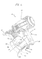
- FIG. 2 is a conventional nailing tool with a hinged side wall of the magazine removed (not shown) to better illustrate the features of the present invention.
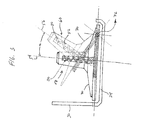
- FIG. 3 is a side view schematic of one embodiment of the magazine present invention showing pivoting of the nail plate and with other portions of the magazine not shown to better illustrate the invention.
- FIG. 4A is a side view schematic of one embodiment of the magazine present invention showing the post in a use position and with other portions of the magazine not shown to better illustrate the invention.
- FIG. 4B is a side view schematic of one embodiment of the magazine present invention showing the post in a load position and with other portions of the magazine not shown to better illustrate the invention.
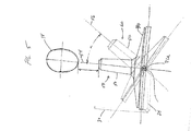
- FIG. 5 is a side view schematic of one embodiment of the magazine present invention showing pivoting of the nail plate and with other portions of the magazine not shown to better illustrate the invention.
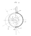
- FIG. 6 is a top view schematic of one embodiment of the magazine present invention showing pivoting of the nail plate and with other portions of the magazine not shown to better illustrate the invention.
- the nail tool 10 generally includes a main body 12 terminating in a nozzle 14 from which the fasteners are propelled and a handle 16 extending from the main body 12 for gripping the tool.
- the magazine 20 can be attached to portion of the handle 16 such as an end 18, a portion of the nozzle 14, or both.
- the magazine 20 includes a magazine tray 22 with a front portion 32 adjacent the nozzle 14 and a rear portion 34 adjacent an end of the handle 16.
- the magazine 20 of the present invention may be used more generally in combination with the other fastener driving tools and in other applications where it is desired to house a coiled strip of fasteners or other similar articles.
- the magazine 20 generally comprises a magazine tray 22 including a lower portion or base 24 having a generally circular shape and a generally circular side wall portion 26 extending upwardly from the lower portion 24.
- a first side wall portion defines an open upper portion 28 of the magazine tray over which a cover (not shown) may be removably or hingedly disposed to enclose a coiled strip of nails, not shown but generally known.
- a second side wall portion 30 defines a closed upper portion of the magazine.
- Prior art Fig. 1 illustrates, for example, a known cover removably coupled to the magazine tray to provide access to the interior to permit loading of a nail coil and adjustment of the nail plate to accommodate different sized fasteners or nails. While Fig. 1 shows a cover pivotably connected to the magazine tray and having a pivot point near the handle, it is known to provide a cover that pivots about a point near the nozzle as shown for example in US 6,152,346.
- the magazine 20 includes a post 50 that extends from the magazine tray 22, and more particularly from a nail plate 70 that has a generally circular shape and is sized to fit within the magazine tray 22 generally parallel to the lower portion or base 24 to support a coiled strip of nails on an upper surface of the nail plate 70, as is generally known.
- the post 50 extends generally perpendicular from a generally central portion of the nail plate 70, about which a coiled strip of nails supported on the nail plate 70 is disposed.
- the post 50 is stationarily located on the nail plate 70 and may, in some embodiments, be fixed to the nail plate 70.
- the nail plate 70 may be vertically adjustable with respect to the lower portion or base 24 of the magazine tray 22 to accommodate different sized fasteners or nails.
- the post 50 is oriented in a use position 58 such that individual nails or fasteners can be driven through the nozzle 14 into a workpiece.
- the post 50 defines a first axis 54 extending along its longitudinal length.
- the post 50 can be oriented to a load position (not shown) that is offset from the use position 58.
- the post 50 defines a second axis (not shown) extending along its longitudinal length.
- the load position is that position of the post 50 where a nail coil can be installed about the post 50 and on the nail plate 70.
- the offset is desirably an angular offset ⁇ and can range from about 1° to about 90°, desirably from about 10° to about 45°, and more desirably from about 20° to about 40°. In some embodiments, the angular offset ⁇ can be about 30°.
- the magazine 20 may be rotatably attached to the tool 10, either at one end of the handle 18, at the nozzle 14, or both.
- the rotatable attachment is desirably manually selectable so that the magazine 20 can be locked so that the post 50 is in a use position 58 but can be unlocked so that the post 50 is in a load position 60 (as can be contemplated by Fig. 3).
- the magazine 50 is rotatably attached to one end of the handle 18 and is rotatably secured by a wing nut 40.
- other devices to achieve selective locking of the magazine 20 with respect to the tool 10 can be used. It is to be understood, however, that the magazine can be rotatably attached in any suitable manner to achieve the desired offset.
- the nail plate 70 is pivotablely connected to a lower portion or base 24 of the magazine tray 22.
- the nail plate 70 has a pivot point 72 adjacent the open portion of the magazine 28 between the front 32 and rear 34 portion of the magazine.
- the nail plate 70 and thus, the post 50 will pivot outwardly away from the handle 16 and toward the open portion 28 of the magazine to a load position 60.
- the nail plate 70 pivots in a plane that is perpendicular to a plane of the base.
- the load position 60 is offset from the use position 58 by angular amount identified by ⁇ .
- a biasing element 80 can be provided to bias the post 50 to the load position 60.
- the biasing element 80 can be a coil spring, foam, or other suitable biasing element known to those skilled in the art.
- the biasing element 80 extends into a cavity 52 provided in the interior of the post 50.
- the biasing element 80 may bias the nail plate 70.
- the biasing element 80 has a force such that the weight of a nail coil is sufficient to compress the biasing element 80 so that the post 50 is in the use position 58. In this instance, when the nail coil is depleted and the cover is opened to expose the interior of the magazine tray 22, the absence of any weight from the nails allows the biasing member 80 to pivot the post 50 to a load position 60.
- a latch 90 is provided to operatively connect with the nail plate 70 to selectively secure the post 50 in a use position 58.
- the latch 90 is generally located opposite the pivot point 72.
- the latch may be located in a different area. It may be desirable to provide a latch biasing element 92 to bias the latch 90 into a locking position with the nail plate 70 such that the post 50 is in the use position 58. In this instance, actuating the latch 90 by movement against the latch biasing element 92 will unlock the latch 90 and allow the biasing element 80 to move the post 50 to a load position 60.
- the nail plate 70 has a first pivot point 72a located at the front portion 32 of the magazine and a second pivot point (not shown) located at the rear portion 34 of the magazine. Accordingly, the nail plate 70 and thus, the post 50 can be rotatingly pivoted from a use position 58 to a load position 60.
- the lower portion or base 24 of the magazine tray 22 can be configured so that a portion of the base 24, nail plate 70, and post 50 all rotatingly pivot with respect to the magazine 20 to move the post 50 from a use position 58 to a load position 60.
- the nail plate 70 has a pivot point 72b located at the rear portion 34 of the magazine so that the nail plate 70 and thus, the post 50 can be pivoted from a use position 58 to a load position 60.
- the pivot point 72b can be alternatively located at the front portion 32 of the magazine. It will also be understood that in this embodiment the nail plate 70 pivots about a plane that is parallel to a plane of the lower portion or base.
Landscapes
- Engineering & Computer Science (AREA)
- Mechanical Engineering (AREA)
- Portable Nailing Machines And Staplers (AREA)
Applications Claiming Priority (1)
| Application Number | Priority Date | Filing Date | Title |
|---|---|---|---|
| US58279004P | 2004-06-25 | 2004-06-25 |
Publications (2)
| Publication Number | Publication Date |
|---|---|
| EP1612000A2 true EP1612000A2 (de) | 2006-01-04 |
| EP1612000A3 EP1612000A3 (de) | 2006-06-07 |
Family
ID=34981438
Family Applications (1)
| Application Number | Title | Priority Date | Filing Date |
|---|---|---|---|
| EP05013468A Withdrawn EP1612000A3 (de) | 2004-06-25 | 2005-06-22 | Magazin für Bolzensetzgeräte |
Country Status (3)
| Country | Link |
|---|---|
| EP (1) | EP1612000A3 (de) |
| CN (1) | CN1727123A (de) |
| AU (1) | AU2005202754A1 (de) |
Cited By (2)
| Publication number | Priority date | Publication date | Assignee | Title |
|---|---|---|---|---|
| WO2012006312A1 (en) * | 2010-07-07 | 2012-01-12 | Illinois Tool Works Inc. | Magazine for a nailing tool |
| US12162125B2 (en) | 2020-10-30 | 2024-12-10 | Milwaukee Electric Tool Corporation | Powered fastener driver |
Family Cites Families (5)
| Publication number | Priority date | Publication date | Assignee | Title |
|---|---|---|---|---|
| DE3224089A1 (de) * | 1982-06-29 | 1983-12-29 | Karl M. Reich Maschinenfabrik GmbH, 7440 Nürtingen | Rundmagazin fuer befestiger-eintreibgeraete |
| JPS59120567U (ja) * | 1983-02-02 | 1984-08-14 | 株式会社立川ピン製作所 | エア−ネイラ−のマガジン装置 |
| GB2149754A (en) * | 1983-11-14 | 1985-06-19 | Umberto Monacelli | Magazine for fasteners in coiled form |
| JP3209261B2 (ja) * | 1995-10-24 | 2001-09-17 | マックス株式会社 | 釘打機のマガジン構造 |
| US6126057A (en) * | 1999-02-26 | 2000-10-03 | Li; Ming Chu | Magazine structure for nailing machines |
-
2005
- 2005-06-03 CN CN 200510076045 patent/CN1727123A/zh active Pending
- 2005-06-22 EP EP05013468A patent/EP1612000A3/de not_active Withdrawn
- 2005-06-23 AU AU2005202754A patent/AU2005202754A1/en not_active Abandoned
Cited By (2)
| Publication number | Priority date | Publication date | Assignee | Title |
|---|---|---|---|---|
| WO2012006312A1 (en) * | 2010-07-07 | 2012-01-12 | Illinois Tool Works Inc. | Magazine for a nailing tool |
| US12162125B2 (en) | 2020-10-30 | 2024-12-10 | Milwaukee Electric Tool Corporation | Powered fastener driver |
Also Published As
| Publication number | Publication date |
|---|---|
| AU2005202754A1 (en) | 2006-01-12 |
| CN1727123A (zh) | 2006-02-01 |
| EP1612000A3 (de) | 2006-06-07 |
Similar Documents
| Publication | Publication Date | Title |
|---|---|---|
| US5626274A (en) | Nail strip magazine with spring leaf to bias feeding member and to separate nail strips | |
| US5921454A (en) | Roofing washer-dispensing and fastener-driving machine | |
| US12624575B2 (en) | Multi-point exit device | |
| EP2133180B1 (de) | Werkzeugbehälteranordnung | |
| US5347707A (en) | Roofing washer-dispensing and fastener-driving machine | |
| US6088862A (en) | Hammer with accessories | |
| JPH11511076A (ja) | ファスナ打込機のファスナ長の調節可能なキャニスタタイプ弾倉 | |
| US20080110956A1 (en) | Coil nailing device for construction finishing materials | |
| JPH11507596A (ja) | クギ打込機用の柿板計測器 | |
| US20130068914A1 (en) | Restraining device | |
| US7883124B2 (en) | Gate latch | |
| US7498513B2 (en) | Toolbox with retractable cable and latch | |
| AU2008286729A1 (en) | Fastener device | |
| AU2005202754A1 (en) | Magazine for nail tools | |
| US6126057A (en) | Magazine structure for nailing machines | |
| US7793363B1 (en) | Flushing mechanism for toilet | |
| JP4550388B2 (ja) | 分離要素のロック装置 | |
| EP2590785B1 (de) | Magazin für ein nagelwerkzeug | |
| JP3114794B2 (ja) | 引き戸錠 | |
| JP2550735Y2 (ja) | 固着具打込工具のマガジン | |
| JP3397080B2 (ja) | 打込機及びそのマガジン | |
| JP4254461B2 (ja) | 釘打機の釘収納用マガジン | |
| JP3940231B2 (ja) | 曲面ドアトイレのドア非常開放装置 | |
| JPH0536627Y2 (de) | ||
| JP4239687B2 (ja) | 釘打機の釘収納用マガジン |
Legal Events
| Date | Code | Title | Description |
|---|---|---|---|
| PUAI | Public reference made under article 153(3) epc to a published international application that has entered the european phase |
Free format text: ORIGINAL CODE: 0009012 |
|
| AK | Designated contracting states |
Kind code of ref document: A2 Designated state(s): AT BE BG CH CY CZ DE DK EE ES FI FR GB GR HU IE IS IT LI LT LU MC NL PL PT RO SE SI SK TR |
|
| AX | Request for extension of the european patent |
Extension state: AL BA HR LV MK YU |
|
| PUAL | Search report despatched |
Free format text: ORIGINAL CODE: 0009013 |
|
| AK | Designated contracting states |
Kind code of ref document: A3 Designated state(s): AT BE BG CH CY CZ DE DK EE ES FI FR GB GR HU IE IS IT LI LT LU MC NL PL PT RO SE SI SK TR |
|
| AX | Request for extension of the european patent |
Extension state: AL BA HR LV MK YU |
|
| AKX | Designation fees paid | ||
| STAA | Information on the status of an ep patent application or granted ep patent |
Free format text: STATUS: THE APPLICATION IS DEEMED TO BE WITHDRAWN |
|
| 18D | Application deemed to be withdrawn |
Effective date: 20061208 |
|
| REG | Reference to a national code |
Ref country code: DE Ref legal event code: 8566 |