EP1612005A1 - Drehbare, ein- und ausziehbare Greifvorrichtung für einen Industrieroboter - Google Patents
Drehbare, ein- und ausziehbare Greifvorrichtung für einen Industrieroboter Download PDFInfo
- Publication number
- EP1612005A1 EP1612005A1 EP20050012948 EP05012948A EP1612005A1 EP 1612005 A1 EP1612005 A1 EP 1612005A1 EP 20050012948 EP20050012948 EP 20050012948 EP 05012948 A EP05012948 A EP 05012948A EP 1612005 A1 EP1612005 A1 EP 1612005A1
- Authority
- EP
- European Patent Office
- Prior art keywords
- end effector
- vacuum
- lazy tong
- manifold
- industrial robot
- Prior art date
- Legal status (The legal status is an assumption and is not a legal conclusion. Google has not performed a legal analysis and makes no representation as to the accuracy of the status listed.)
- Granted
Links
- 239000012636 effector Substances 0.000 title claims abstract description 30
- 239000012530 fluid Substances 0.000 claims description 5
- 230000007246 mechanism Effects 0.000 claims description 5
- 238000004891 communication Methods 0.000 claims description 4
- 210000000245 forearm Anatomy 0.000 description 4
- 235000009508 confectionery Nutrition 0.000 description 3
- 238000005266 casting Methods 0.000 description 2
- 238000004806 packaging method and process Methods 0.000 description 2
- 238000010276 construction Methods 0.000 description 1
- 229920002457 flexible plastic Polymers 0.000 description 1
- 230000008676 import Effects 0.000 description 1
- 238000000034 method Methods 0.000 description 1
- 238000012986 modification Methods 0.000 description 1
- 230000004048 modification Effects 0.000 description 1
- 238000011017 operating method Methods 0.000 description 1
- 230000002093 peripheral effect Effects 0.000 description 1
- 230000008569 process Effects 0.000 description 1
- 230000007480 spreading Effects 0.000 description 1
- 238000013519 translation Methods 0.000 description 1
Images


Classifications
-
- B—PERFORMING OPERATIONS; TRANSPORTING
- B25—HAND TOOLS; PORTABLE POWER-DRIVEN TOOLS; MANIPULATORS
- B25J—MANIPULATORS; CHAMBERS PROVIDED WITH MANIPULATION DEVICES
- B25J15/00—Gripping heads and other end effectors
- B25J15/0052—Gripping heads and other end effectors multiple gripper units or multiple end effectors
-
- B—PERFORMING OPERATIONS; TRANSPORTING
- B25—HAND TOOLS; PORTABLE POWER-DRIVEN TOOLS; MANIPULATORS
- B25J—MANIPULATORS; CHAMBERS PROVIDED WITH MANIPULATION DEVICES
- B25J15/00—Gripping heads and other end effectors
- B25J15/06—Gripping heads and other end effectors with vacuum or magnetic holding means
- B25J15/0616—Gripping heads and other end effectors with vacuum or magnetic holding means with vacuum
Definitions
- This invention relates generally to pick-&-place robotics, and more particularly to end effectors used on such equipment.
- the products leaving the wrapping machine are candy bars of a defined length, width and thickness dimension and that they are traveling between lugs or fins of a flighted conveyor that maintains a predetermined gap between products.
- a predetermined count of the candy bars say, one dozen
- the robot employed must be able to simultaneously pick up plural bars from the flighted conveyor, squeeze the several bars together to eliminate the spacing therebetween and then deposit the plural bars as a group in the carton and then repeat the process until the desired count has been boxed.
- Another object of the invention is to provide an end effector capable of compressing and expanding the spacing between plural product grasping devices comprising the end effector.
- Still another object of the invention is to provide an end effector for a robot having a rotatable head capable of both rotating plural products and expanding and contracting the spacing between the plural products picked up by the end effector as the products are being carried by a robot.
- an end effector for an arm of an industrial robot that comprises a plurality of suction tubes coupled in fluid communication to a vacuum manifold where each of the suction tubes is capable of grasping a product.
- the end effector also includes a means for varying the spacing between the plurality of suction tubes as well as a means for rotating the vacuum manifold and the means for varying the spacing between the plurality of suction tubes relative to the arm of the industrial robot carrying the end effector.
- the means for varying the spacing between the plurality of suction tubes may comprise a lazy tong linkage assembly that is coupled to a linear actuator such that extension of the linear actuator results in a spreading of the distance between the suction tubes and retraction of the linear actuator results in a squeezing of the plurality of suction tubes together.
- the means for rotating the vacuum manifold preferably comprises a pneumatically operated rotary actuator having a rotary platform journaled to a body member where the rotary actuator is disposed between the arm of the industrial robot and the vacuum manifold.
- an end effector for use on an industrial robot such as a Delta Robot of the type described in U.S. Patent 4,976,582 to Raymond Clavel (the Clavel '482 patent).
- the patent describes a robot for handling products in a three-dimensional space and those skilled in the art may refer to that patent for a description of a robot with which the present invention may be utilized.
- Such a robot is designed for high-speed and high-accuracy pick-&-place applications, such as may be effectively used in the packaging machine industry, for picking products from a conveyor belt and placing them in cartons or to the infeed of a high-speed wrapping machine with a predetermined orientation and spacing between products.
- the Delta Robot includes a generally triangular-shaped main casting 1 having three rotatable shafts 2 journaled for rotation about horizontal axes extending generally parallel to the three sides of the triangular casting 1.
- Each of the three shafts is arranged to be driven by a servo motor 3 for rotating the arms 4 in a vertical plane.
- Rotary encoders 7 on the servo motor 3 feed positional information to a main controller module 12.
- At the free ends of the arms 4 are crossbars of a predetermined length dimension and carrying a detachable connector, such as ball & socket joints 26, at a opposed ends thereof.
- the detachable ball & socket joints 26 couple the cross bars to a pair of rods comprising a total of six forearms 5, all of equal length.
- a triangular-shaped base plate member 8 Suspended from the lower ends of the six forearms 5 is a triangular-shaped base plate member 8. More particularly, cross rods project laterally from the base plate 8 proximate the three vertices thereof and detachable connectors, e.g., ball & socket joints 27, are used to join the lower ends of the forearm members 5 to the cross rods. Supported from the underside of the base plate 8 is an end effector 9 which may comprise a vacuum cup or other type of gripping member.
- the base plate 8 carrying the end effector 9 undergoes pure translation without rotation in first swinging to pick up a product located in a first area and transporting it to a second area for release.
- the base plate 8 of the Delta Robot is shown with the end effector 10 of the present invention attached to the undersurface thereof by a series of bolts, as at 12, which extend into threaded bores formed in the top surface 14 of a rotary actuator 16.
- the rotary actuator 16 may be of a type manufactured and sold by Numatics Incorporated of Highland, Michigan.
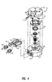
- the rotary actuator 16 includes a rotary platform 18 ( Figure 2) journaled to a body member 20 where the body member 20 is affixed to the underside of the base plate 8 of the Delta Robot. Under pneumatic forces, the rotary platform 18 can be made to swivel through a predetermined arc.
- the rotary actuator 16 is mounted on a frame structure that is indicated generally by numeral 22 in Figure 1. More particularly, a series of standoffs as at 24, secure the rotary actuator 16 to the frame 22 so as to maintain a predetermined distance between the underside of the rotary platform 18 and the upper surface of the frame 22.
- the frame 22 comprises first and second tubular vacuum manifolds 26 and 28 that are held in parallel, spaced-apart relationship by opposed end plates 30 and 32.
- the tubular manifold 28 has a vacuum inlet port 34 adapted to be connected by flexible tubing, not shown, to a vacuum source.
- the tubular manifold member 26 also has a vacuum inlet port 36 that is hidden from view in Figure 1, but visible in the end view of Figure 3.
- a vacuum can be selectively applied to one or both manifolds.
- Each of the manifold members 26 and 28 has a plurality of vacuum outlet ports, as at 38.
- first and second linear actuators 40 and 42 bolted to the underside of the rotary platform 18 are first and second linear actuators 40 and 42.
- Each comprises a pneumatic 2-way cylinder whose reciprocally movable outlet shafts 44 and 46 terminate in fittings 48 and 50.
- These fittings are pivotally connected by a pin 52 that passes through a standoff 54 to end linkages 56 and 58 of a lazy tong linkage assembly that is indicated generally by numeral 60.
- the lazy tong linkage assembly 60 comprises a plurality of pairs of diagonal linkages, where the members of each pair are pivotally joined at their centers and are also pivotally joined to an adjacent pair of diagonal linkages at their respective ends, as perhaps best seen in the perspective view of Figure 1.
- FIG 2 attached to the lazy tong assembly 60 proximate the center of the diagonal linkages thereof are product graspers, here shown as downwardly extending rigid tubes, as at 62, each supporting a pair of suction cups, as at 64, that are in fluid communication with the central lumen of the rigid tubes 62 by way of tubular stubs, as at 66. While the illustrated embodiment uses pneumatic graspers, it is to be understood that other mechanical or electrically operated graspers may also be used.
- Short lengths of flexible plastic tubing are used to connect the manifold outlet ports 38 to corresponding input ports 68 near the upper ends of the rigid tubes 62.
- the body member 20 thereof includes a pair of bores 70 and 72 that receive generally cylindrical pneumatic pistons 74 and 76 therein.
- the piston members include a gear rack 78 machined into a flattened portion of the periphery of the otherwise cylindrical pistons.
- the body member 20 includes a centrally located vertical cylindrical bore 84 for receiving a pinion gear 86 and bearings 88 and 90 therein.
- the gear teeth on the pinion 86 are arranged to mate with the gear rack 78 on the pistons 74 and 76 such that when the pistons are made to move reciprocally in the bores 70 and 72, the pinion gear 86 will rotate about its central axis.
- tubular caps as at 92 are screwed into threads formed the bores 70 and 72 of the body member 20.
- the pistons can be made to move toward the center of the body member 20, rotating the spur gear 86 in a first direction.
- the alternate pistons will be forced toward the periphery of the body member 20 causing the pinion gear 86 to rotate in the opposite direction.
- a retainer ring 96 is fastened by screws 98 to the surface face of the body member 20 holding the bearings 88, 90 and 100 that journal the pinion gear 86 in place.
- the rotary platform 18 is secured to an upwardly projecting shaft 102 of the pinion gear 86 so as to rotate with the pinion gear.
- Formed in the undersurface of the rotary platform 18 is an annular groove (not shown) into which a projection 104 on the body member 20 is arranged to fit.
- Threaded bores 106 and 108 extend radially into the peripheral surface of the rotary platform 18 and intersect with the annular groove.
- Setscrews 110 and 112 are inserted into the threaded bores 106 and 108 to cooperate with the stop 104 to define the end points of the arc through which the rotary platform 18 may rotate.
- the linear actuators 40 and 42 can have their piston rods 44 and 46 extended or retracted, thereby varying the spacing between the plurality of rigid tubes and the products carried thereby by virtue of the lazy tong linkage mechanism that is operatively coupled to the reciprocally movable piston rods 44 and 46.
- the rotary platform 18 can be made to spin through a predetermined arc as set by the adjustment screws 110 and 112 to thereby rotate the frame 22, the lazy tong assembly 60 and the rigid tubes 62 relative to the base plate 8 of the robot arm with which the end effector 10 of the present invention is used.
- a plurality of objects may simultaneously be picked up from a conveyor belt for placement in a carton traveling along an adjacent conveyor belt.
- the spacing between the objects can be varied in transit.
- all of the objects can be rotated while the objects are in transit under control of the robot arm.
Landscapes
- Engineering & Computer Science (AREA)
- Robotics (AREA)
- Mechanical Engineering (AREA)
- Manipulator (AREA)
Applications Claiming Priority (1)
| Application Number | Priority Date | Filing Date | Title |
|---|---|---|---|
| US10/881,230 US7234744B2 (en) | 2004-06-30 | 2004-06-30 | Rotatable, squeeze-spread end effector for industrial robot |
Publications (2)
| Publication Number | Publication Date |
|---|---|
| EP1612005A1 true EP1612005A1 (de) | 2006-01-04 |
| EP1612005B1 EP1612005B1 (de) | 2015-08-12 |
Family
ID=34937486
Family Applications (1)
| Application Number | Title | Priority Date | Filing Date |
|---|---|---|---|
| EP05012948.5A Expired - Lifetime EP1612005B1 (de) | 2004-06-30 | 2005-06-16 | Drehbare, ein- und ausziehbare Greifvorrichtung für einen Industrieroboter |
Country Status (3)
| Country | Link |
|---|---|
| US (1) | US7234744B2 (de) |
| EP (1) | EP1612005B1 (de) |
| ES (1) | ES2548486T3 (de) |
Cited By (5)
| Publication number | Priority date | Publication date | Assignee | Title |
|---|---|---|---|---|
| GB2436100A (en) * | 2006-03-16 | 2007-09-19 | Aew Delford Group Ltd | Gripper device for picking and placing a plurality of items |
| EP2048098A1 (de) * | 2007-10-10 | 2009-04-15 | Langen Packaging Inc. | Vorrichtung mit mehreren Eingriffsvorrichtung |
| FR2935957A1 (fr) * | 2008-09-18 | 2010-03-19 | Saint Etienne Automation | Installation pour la mise en barquettes d'au moins une tranche d'un produit prealablement tranche. |
| ES2434857R1 (es) * | 2012-06-12 | 2014-06-10 | Europea De Soluciones Alimentarias, S.L. | Pinza para encajado de pepinos |
| EP3741517A1 (de) * | 2019-05-20 | 2020-11-25 | Gerhard Schubert GmbH | Verfahren zum umsetzen von produkten sowie hierfür geeigneter umsetz-roboter |
Families Citing this family (26)
| Publication number | Priority date | Publication date | Assignee | Title |
|---|---|---|---|---|
| GB2409427A (en) * | 2003-12-23 | 2005-06-29 | Bausch & Lomb | Handling moulded opthalmic lenses |
| KR100622415B1 (ko) * | 2004-12-06 | 2006-09-19 | 미래산업 주식회사 | 반도체 소자 테스트 핸들러의 소자 반송장치 |
| KR100648919B1 (ko) * | 2005-11-15 | 2006-11-24 | (주)테크윙 | 픽앤플레이스 장치 |
| US7703260B1 (en) | 2006-06-15 | 2010-04-27 | Watkins Norman M | Circular motion case packing system |
| US20080003092A1 (en) * | 2006-06-30 | 2008-01-03 | Petar Baclija | Rotary union connection |
| EP1882652B1 (de) * | 2006-07-26 | 2008-07-16 | INDAG Gesellschaft für Industriebedarf mbH & Co. Betriebs KG | Greifeinrichtung |
| US8276959B2 (en) * | 2008-08-08 | 2012-10-02 | Applied Materials, Inc. | Magnetic pad for end-effectors |
| US8166638B2 (en) * | 2009-06-11 | 2012-05-01 | Asm Assembly Automation Ltd | Rotary clip bonder |
| CN102463535B (zh) | 2010-11-04 | 2013-11-20 | 鸿富锦精密工业(深圳)有限公司 | 夹持装置 |
| ES2417338T3 (es) * | 2011-03-11 | 2013-08-07 | Cama1 S.P.A. | Cabezal de sujeción para un manipulador o robot de una máquina de hacer envases de cartón |
| ES2675796T5 (es) | 2011-03-16 | 2023-04-21 | Cama1 S P A | Máquina y método para embalar artículos en cajas de cartón |
| AT511404B1 (de) * | 2011-05-11 | 2015-10-15 | Haas Food Equipment Gmbh | Backofen |
| DE102011075625B4 (de) * | 2011-05-11 | 2021-08-26 | J. Schmalz Gmbh | Vorrichtung zum Greifen und Halten von Werkstücken mittels Unterdruck |
| AT511403B1 (de) * | 2011-05-11 | 2015-10-15 | Haas Food Equipment Gmbh | Backofen |
| US8876182B2 (en) * | 2012-10-01 | 2014-11-04 | Festo Corporation | Integrated two dimensional robotic palm for variable pitch positioning of multiple transfer devices |
| CN107322579B (zh) * | 2017-08-10 | 2020-05-05 | 福建金煌机电设备有限公司 | 一种智能分捡机 |
| KR101884189B1 (ko) * | 2018-01-29 | 2018-08-01 | 윤정원 | 화장품 용기 운반용 로봇핸드 |
| US12202127B2 (en) | 2019-03-31 | 2025-01-21 | Robotiq Inc. | Adjustable suction gripper |
| US11022953B2 (en) * | 2019-05-07 | 2021-06-01 | Cna Manufacturing Systems, Inc. | Flexible tooling system |
| US20200407165A1 (en) | 2019-06-28 | 2020-12-31 | Walmart Apollo, Llc | Automated in-rack picking |
| CN110422622A (zh) * | 2019-08-23 | 2019-11-08 | 天津齐物科技有限公司 | 圆柱型单体动力电池夹取装置 |
| US10913166B1 (en) | 2019-09-25 | 2021-02-09 | Syntegon Packaging Technology, Inc. | Gripper |
| KR102281833B1 (ko) * | 2020-03-04 | 2021-07-26 | 주식회사 클레버 | 이차전지 셀 폴딩공정용 이차전지 셀 공급장치 |
| CN111747108A (zh) * | 2020-07-09 | 2020-10-09 | 上海思客琦自动化工程有限公司 | 一种可夹持多组锂电池模组的电动夹具及夹持方法 |
| US12162687B1 (en) * | 2021-05-10 | 2024-12-10 | Amazon Technologies, Inc. | Container transporters with dual container slots |
| US20230399182A1 (en) * | 2022-06-09 | 2023-12-14 | Ats Automation Tooling Systems Inc. | Serial multi-up effector and rotary table for use in an automated assembly line |
Citations (4)
| Publication number | Priority date | Publication date | Assignee | Title |
|---|---|---|---|---|
| US4744595A (en) * | 1984-11-09 | 1988-05-17 | Leif Hoegh & Co. A/S | Hoisting apparatus for groupwise transfer of cargo units, such as paper rolls |
| JPH06156410A (ja) * | 1992-09-24 | 1994-06-03 | Shizukou Kk | 物品グリッパー用間隔調整装置 |
| JPH06262572A (ja) * | 1993-03-17 | 1994-09-20 | Kawashima Packaging Mach Ltd | 箱詰め用バキューム式ロボットハンド |
| US20030235491A1 (en) * | 2002-04-22 | 2003-12-25 | Subotincic Milos Misha | End effector with multiple pick-up members |
Family Cites Families (16)
| Publication number | Priority date | Publication date | Assignee | Title |
|---|---|---|---|---|
| US3630389A (en) * | 1970-09-30 | 1971-12-28 | Gen Electric | Material-handling apparatus |
| SE362231B (de) * | 1972-01-18 | 1973-12-03 | Asea Ab | |
| US4355936A (en) * | 1980-08-28 | 1982-10-26 | Diamond International Corporation | Egg transfer apparatus |
| FR2495586A1 (fr) * | 1980-12-09 | 1982-06-11 | Remy & Cie E P | Tete extensible pour la prehension et la modification d'un groupe d'objets |
| JPS6148180A (ja) * | 1984-08-11 | 1986-03-08 | Fuji Photo Film Co Ltd | 回転磁気記録体装置 |
| US4571320A (en) * | 1984-10-31 | 1986-02-18 | General Motors Corporation | Method and apparatus for loading and unloading sheet molding compound in and from a press |
| IT1190555B (it) * | 1986-03-19 | 1988-02-16 | Ferrero Spa | Dispositivo di presa particolarmente per apparecchiature automatiche di sollevamento e trasporto di impianti per il confezionamento di prodotti alimentari |
| DE3926121A1 (de) * | 1989-08-08 | 1991-02-14 | Focke & Co | Vorrichtung zum foerdern von lagen aus einer mehrzahl von einzelgegenstaenden |
| IT1271481B (it) * | 1993-10-11 | 1997-05-28 | Vortex Systems Srl | Dispositivo di manipolazione di prodotti e relativa apparecchiatura |
| JPH07223308A (ja) * | 1994-02-15 | 1995-08-22 | Toppan Printing Co Ltd | 印刷紙束の配送札自動添付装置 |
| US5865487A (en) * | 1996-05-23 | 1999-02-02 | Motorola, Inc. | Pick-and-place tool for vacuum and magnetic coupling |
| US5735200A (en) * | 1996-07-01 | 1998-04-07 | Chrysler Corporation | Stamping press loader |
| KR100248704B1 (ko) * | 1997-11-08 | 2000-03-15 | 정문술 | 반도체 소자검사기의 소자 간격조절장치 |
| DE29801158U1 (de) * | 1998-01-24 | 1998-04-09 | MSK-Verpackungs-Systeme GmbH, 47533 Kleve | Lagenübersetzer für Palettierer o.dgl. |
| US6439631B1 (en) * | 2000-03-03 | 2002-08-27 | Micron Technology, Inc. | Variable-pitch pick and place device |
| US6374996B1 (en) * | 2000-07-03 | 2002-04-23 | Tsung-Chang Hsieh | Circuit board carrier |
-
2004
- 2004-06-30 US US10/881,230 patent/US7234744B2/en not_active Expired - Lifetime
-
2005
- 2005-06-16 ES ES05012948.5T patent/ES2548486T3/es not_active Expired - Lifetime
- 2005-06-16 EP EP05012948.5A patent/EP1612005B1/de not_active Expired - Lifetime
Patent Citations (4)
| Publication number | Priority date | Publication date | Assignee | Title |
|---|---|---|---|---|
| US4744595A (en) * | 1984-11-09 | 1988-05-17 | Leif Hoegh & Co. A/S | Hoisting apparatus for groupwise transfer of cargo units, such as paper rolls |
| JPH06156410A (ja) * | 1992-09-24 | 1994-06-03 | Shizukou Kk | 物品グリッパー用間隔調整装置 |
| JPH06262572A (ja) * | 1993-03-17 | 1994-09-20 | Kawashima Packaging Mach Ltd | 箱詰め用バキューム式ロボットハンド |
| US20030235491A1 (en) * | 2002-04-22 | 2003-12-25 | Subotincic Milos Misha | End effector with multiple pick-up members |
Non-Patent Citations (2)
| Title |
|---|
| PATENT ABSTRACTS OF JAPAN vol. 018, no. 483 (M - 1670) 8 September 1994 (1994-09-08) * |
| PATENT ABSTRACTS OF JAPAN vol. 018, no. 666 (M - 1724) 15 December 1994 (1994-12-15) * |
Cited By (7)
| Publication number | Priority date | Publication date | Assignee | Title |
|---|---|---|---|---|
| GB2436100A (en) * | 2006-03-16 | 2007-09-19 | Aew Delford Group Ltd | Gripper device for picking and placing a plurality of items |
| GB2436100B (en) * | 2006-03-16 | 2008-02-13 | Aew Delford Group Ltd | Gripper device |
| EP2048098A1 (de) * | 2007-10-10 | 2009-04-15 | Langen Packaging Inc. | Vorrichtung mit mehreren Eingriffsvorrichtung |
| US8534727B2 (en) | 2007-10-10 | 2013-09-17 | Langen Packaging Inc. | Device with multiple engagement members |
| FR2935957A1 (fr) * | 2008-09-18 | 2010-03-19 | Saint Etienne Automation | Installation pour la mise en barquettes d'au moins une tranche d'un produit prealablement tranche. |
| ES2434857R1 (es) * | 2012-06-12 | 2014-06-10 | Europea De Soluciones Alimentarias, S.L. | Pinza para encajado de pepinos |
| EP3741517A1 (de) * | 2019-05-20 | 2020-11-25 | Gerhard Schubert GmbH | Verfahren zum umsetzen von produkten sowie hierfür geeigneter umsetz-roboter |
Also Published As
| Publication number | Publication date |
|---|---|
| ES2548486T3 (es) | 2015-10-16 |
| US20060017298A1 (en) | 2006-01-26 |
| US7234744B2 (en) | 2007-06-26 |
| EP1612005B1 (de) | 2015-08-12 |
Similar Documents
| Publication | Publication Date | Title |
|---|---|---|
| EP1612005B1 (de) | Drehbare, ein- und ausziehbare Greifvorrichtung für einen Industrieroboter | |
| US8240726B2 (en) | End effector with multiple pick-up members | |
| CN104227719B (zh) | 用于处置物品的设备和用于运行这种设备的方法 | |
| CN108214535B (zh) | 一种同步控制机械手 | |
| JP7173643B2 (ja) | 多機能ロングアームのグリッピング機構 | |
| US20160114481A1 (en) | Device for the movement and positioning of an element in space | |
| CN212736047U (zh) | 一种适于抓取不同形状工件的机械手 | |
| US4765668A (en) | Robot end effector | |
| CN107107333B (zh) | 用于对如包捆物、零散货物等商品进行操作的设备和方法 | |
| CN107745972A (zh) | 一种用于单双箱抓取的真空吸附式末端执行器 | |
| WO2010025471A1 (en) | Article handling device | |
| WO2022189456A1 (en) | Robotic gripper | |
| CN116175631B (zh) | 一种用于箱式制氧机的抓取机械手 | |
| EP0701880B1 (de) | Vorrichtung zur Handhabung, insbesondere von Werkstücken, Werkzeugen oder dergleichen | |
| CN207726370U (zh) | 一种用于单双箱抓取的真空吸附式末端执行器 | |
| GB2591071A (en) | End effector | |
| CN106625741B (zh) | 支撑连杆带轮传动直线平动机器人手装置 | |
| EP3228425B1 (de) | Vorrichtung zum bewegen und positionieren eines elements im raum | |
| CN121589780B (en) | Four-degree-of-freedom high-speed parallel pickup robot | |
| CN220333083U (zh) | 一种变轨夹具 | |
| CN221436508U (zh) | 机械抓手及工业机器人 | |
| CN215201993U (zh) | 一种三轴旋转伺服搬运机械手 | |
| CN106671119A (zh) | 一种工业机器人手臂端部执行器 | |
| HK1245191A1 (en) | Device for the movement and positioning of an element in space | |
| HK1245191B (en) | Device for the movement and positioning of an element in space |
Legal Events
| Date | Code | Title | Description |
|---|---|---|---|
| PUAI | Public reference made under article 153(3) epc to a published international application that has entered the european phase |
Free format text: ORIGINAL CODE: 0009012 |
|
| AK | Designated contracting states |
Kind code of ref document: A1 Designated state(s): AT BE BG CH CY CZ DE DK EE ES FI FR GB GR HU IE IS IT LI LT LU MC NL PL PT RO SE SI SK TR |
|
| AX | Request for extension of the european patent |
Extension state: AL BA HR LV MK YU |
|
| 17P | Request for examination filed |
Effective date: 20060511 |
|
| AKX | Designation fees paid |
Designated state(s): CH DE ES FR GB LI |
|
| 17Q | First examination report despatched |
Effective date: 20080623 |
|
| GRAP | Despatch of communication of intention to grant a patent |
Free format text: ORIGINAL CODE: EPIDOSNIGR1 |
|
| INTG | Intention to grant announced |
Effective date: 20150204 |
|
| GRAS | Grant fee paid |
Free format text: ORIGINAL CODE: EPIDOSNIGR3 |
|
| GRAA | (expected) grant |
Free format text: ORIGINAL CODE: 0009210 |
|
| AK | Designated contracting states |
Kind code of ref document: B1 Designated state(s): CH DE ES FR GB LI |
|
| REG | Reference to a national code |
Ref country code: GB Ref legal event code: FG4D |
|
| REG | Reference to a national code |
Ref country code: CH Ref legal event code: EP |
|
| REG | Reference to a national code |
Ref country code: DE Ref legal event code: R096 Ref document number: 602005047192 Country of ref document: DE |
|
| REG | Reference to a national code |
Ref country code: ES Ref legal event code: FG2A Ref document number: 2548486 Country of ref document: ES Kind code of ref document: T3 Effective date: 20151016 |
|
| REG | Reference to a national code |
Ref country code: DE Ref legal event code: R097 Ref document number: 602005047192 Country of ref document: DE |
|
| PLBE | No opposition filed within time limit |
Free format text: ORIGINAL CODE: 0009261 |
|
| STAA | Information on the status of an ep patent application or granted ep patent |
Free format text: STATUS: NO OPPOSITION FILED WITHIN TIME LIMIT |
|
| REG | Reference to a national code |
Ref country code: FR Ref legal event code: PLFP Year of fee payment: 12 |
|
| 26N | No opposition filed |
Effective date: 20160513 |
|
| REG | Reference to a national code |
Ref country code: FR Ref legal event code: PLFP Year of fee payment: 13 |
|
| REG | Reference to a national code |
Ref country code: FR Ref legal event code: PLFP Year of fee payment: 14 |
|
| PGFP | Annual fee paid to national office [announced via postgrant information from national office to epo] |
Ref country code: CH Payment date: 20180626 Year of fee payment: 14 |
|
| PGFP | Annual fee paid to national office [announced via postgrant information from national office to epo] |
Ref country code: FR Payment date: 20180625 Year of fee payment: 14 |
|
| PGFP | Annual fee paid to national office [announced via postgrant information from national office to epo] |
Ref country code: GB Payment date: 20180626 Year of fee payment: 14 Ref country code: ES Payment date: 20180723 Year of fee payment: 14 Ref country code: DE Payment date: 20180807 Year of fee payment: 14 |
|
| REG | Reference to a national code |
Ref country code: DE Ref legal event code: R119 Ref document number: 602005047192 Country of ref document: DE |
|
| REG | Reference to a national code |
Ref country code: CH Ref legal event code: PL |
|
| GBPC | Gb: european patent ceased through non-payment of renewal fee |
Effective date: 20190616 |
|
| PG25 | Lapsed in a contracting state [announced via postgrant information from national office to epo] |
Ref country code: DE Free format text: LAPSE BECAUSE OF NON-PAYMENT OF DUE FEES Effective date: 20200101 Ref country code: GB Free format text: LAPSE BECAUSE OF NON-PAYMENT OF DUE FEES Effective date: 20190616 |
|
| PG25 | Lapsed in a contracting state [announced via postgrant information from national office to epo] |
Ref country code: CH Free format text: LAPSE BECAUSE OF NON-PAYMENT OF DUE FEES Effective date: 20190630 Ref country code: LI Free format text: LAPSE BECAUSE OF NON-PAYMENT OF DUE FEES Effective date: 20190630 |
|
| PG25 | Lapsed in a contracting state [announced via postgrant information from national office to epo] |
Ref country code: FR Free format text: LAPSE BECAUSE OF NON-PAYMENT OF DUE FEES Effective date: 20190630 |
|
| REG | Reference to a national code |
Ref country code: ES Ref legal event code: FD2A Effective date: 20201028 |
|
| PG25 | Lapsed in a contracting state [announced via postgrant information from national office to epo] |
Ref country code: ES Free format text: LAPSE BECAUSE OF NON-PAYMENT OF DUE FEES Effective date: 20190617 |