EP1612320A1 - Bügelvorrichtung mit einem Bügeleisen und einer eine Schutzkappe aufweisenden tragbaren Basis - Google Patents
Bügelvorrichtung mit einem Bügeleisen und einer eine Schutzkappe aufweisenden tragbaren Basis Download PDFInfo
- Publication number
- EP1612320A1 EP1612320A1 EP05356091A EP05356091A EP1612320A1 EP 1612320 A1 EP1612320 A1 EP 1612320A1 EP 05356091 A EP05356091 A EP 05356091A EP 05356091 A EP05356091 A EP 05356091A EP 1612320 A1 EP1612320 A1 EP 1612320A1
- Authority
- EP
- European Patent Office
- Prior art keywords
- flap
- iron
- protective flap
- protective
- base
- Prior art date
- Legal status (The legal status is an assumption and is not a legal conclusion. Google has not performed a legal analysis and makes no representation as to the accuracy of the status listed.)
- Granted
Links
Images



Classifications
-
- D—TEXTILES; PAPER
- D06—TREATMENT OF TEXTILES OR THE LIKE; LAUNDERING; FLEXIBLE MATERIALS NOT OTHERWISE PROVIDED FOR
- D06F—LAUNDERING, DRYING, IRONING, PRESSING OR FOLDING TEXTILE ARTICLES
- D06F79/00—Accessories for hand irons
- D06F79/02—Stands or supports neither attached to, nor forming part of, the iron or ironing board
-
- D—TEXTILES; PAPER
- D06—TREATMENT OF TEXTILES OR THE LIKE; LAUNDERING; FLEXIBLE MATERIALS NOT OTHERWISE PROVIDED FOR
- D06F—LAUNDERING, DRYING, IRONING, PRESSING OR FOLDING TEXTILE ARTICLES
- D06F75/00—Hand irons
- D06F75/08—Hand irons internally heated by electricity
- D06F75/10—Hand irons internally heated by electricity with means for supplying steam to the article being ironed
- D06F75/12—Hand irons internally heated by electricity with means for supplying steam to the article being ironed the steam being produced from water supplied to the iron from an external source
Definitions
- the present invention relates to an ironing apparatus comprising an iron and a portable base comprising a location for laying the iron when the latter is not in use, and relates more particularly to a protective flap carried by the base and fold down on the iron for storage or transport of the ironing unit.
- an object of the present invention is to overcome these disadvantages by providing an ironing apparatus comprising a portable base provided with a location for placing an iron and a protective flap in which the protective flap provides, in addition to its iron protection function, also a safety function by conditioning the operation or use of a generator element in the open or closed position of the shutter.
- the subject of the invention is an ironing apparatus comprising an iron and a portable base comprising a location for laying the iron, the apparatus comprising a protective shutter connected to the base that can occupy an open position.
- the protective flap is arranged laterally to said location so as to allow access thereto and a closed position in which the protective flap covers the major part of the location so as to prevent access to the iron when the latter rests on said location, characterized in that in the open or closed position, the protective shutter hides an element of the ironing apparatus intended to be handled by the user so as to prevent its access and thus provide a safety function additional to that related to the accessibility to iron.
- Such a characteristic makes it possible to reinforce the safety of use of the ironing appliance by only allowing access to or the operation of certain elements of the appliance only when the protective shutter is in the safest position for the ironing appliance. user.
- Such a feature also has the advantage of a very low cost of implementation.
- the element of the apparatus is the filling orifice of a reservoir, the filling orifice being masked by the protective flap in the open position so that the reservoir can not be filled only when the protective shutter is in the closed position.
- Such a feature has the advantage of improving safety when filling the tank by preventing access to iron, including its hot sole.
- the element is a removable reservoir whose extraction direction is such that, in the open position, the protective flap prevents the withdrawal of the reservoir from the base, the withdrawal of the reservoir being possible that when the protective shutter is in the closed position.
- the protective flap comprises several flap members which are retractable on each other and the element hidden by the flap is a transport handle which is carried by one of the flap elements which are covered by another shutter element when the protective shutter is in the open position.
- Such a characteristic has the advantage of allowing the transport of the ironing unit by means of the carrying handle only when the shutter is closed, thus ensuring greater safety during transport.
- the base comprises a power supply cord opening into a storage cavity and the protective flap prevents access to the storage cavity of the power cord when he is in a closed position.
- the apparatus is a steam generator, the portable base comprising a tank connected to a tank for producing steam under pressure and the iron being supplied with steam by the tank.
- FIG. 1 represents an ironing apparatus, of the steam generator type, conventionally comprising an iron 1 resting on a portable base 2 incorporating a tank for producing steam under pressure, not shown in the figures.
- the iron 1 comprises a sole 10 provided with a heating resistor and is connected to the base by a flexible cord 3 incorporating electrical supply wires of the heating resistor and a steam supply duct of the iron soleplate. .
- the base 2 comprises a flat lower surface 20 and has, above this surface, seen from the side, a substantially circular contour having a truncated portion defining an inclined plane 21 constituting a location for resting the iron 1, such a configuration having the advantage of great ergonomics of use.
- the inclination of the inclined plane 21 is of the order of 30 ° relative to the horizontal.
- the base 2 comprises, at the foot of the inclined plane 21, a rising portion forming a stopper 22 on which rests the heel of the iron when the iron is placed on the inclined plane, the stopper 22 advantageously having a rounded shape that fits into the a cavity 11 of the heel of the iron 1 so as to laterally immobilize the latter.
- the base 2 also comprises, on the back of the stopper 22, a panel 23 for controlling the steam generator and encloses in the space under the inclined plane 21, a removable tank 24, better visible in Figure 2.
- the tank 24 is intended to supply water to the tank of the generator and is provided with a filling door 24a.
- the steam generator is electrically powered by means of a power cord coming out of the base at a storage cavity comprising an automatic cord winder.
- a switch 26 is provided near this cavity for starting or stopping the heating means of the generator tank.
- the base 2 comprises a protective flap 4 consisting of two elements 41, 42 retractable one on the other, made of transparent plastic material such as plexiglass.
- Each element 41, 42 of the protective shutter 4 is pivotally mounted on the base by means of a hinge 5 disposed substantially midway between the two longitudinal ends of the base 2 and at mid-height between the lower surface 20 and the inclined plane 21 of the base 2.
- the elements 41, 42 of the protective flap 4 have a U-shaped cross section and one of the two elements of the flap, called outer flap element 41, has dimensions slightly greater than the other. element, called the inner flap member 42, so that the outer flap member 41 can retract onto the inner flap member 42.
- the outer flap 41 and inner 42 elements comprise stops that cooperate with each other so that the inner flap member 42 is rotated by the outer flap member 41 with a low overlap between the two flap elements. 41, 42 when the outer flap member 41 is manipulated in the closing direction and with an almost total overlap of the inner flap member 42, when the outer flap member 41 is manipulated in the direction of the opening.
- the inner flap member 42 also has an edge 43 curved inwardly of the flap which limits the rotational stroke of the inner flap member 42, when the protective flap 4 is open, coming to bear on the periphery inclined plane 21.
- an automatic locking device is integrated in one of the hinges 5 and ensures the locking of the shutter elements 41, 42 in the closed position, an unlocking button 51 being provided in the center of the hinge 5 to disable the locking device and allow the opening of the flap members 41, 42 by the user.
- the unlocking button 51 may also be advantageously separated from the hinge 5, so that the clearance necessary for the operation of the unlocking button does not create an additional game at the hinge 5.
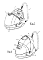
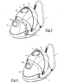
- the protective flap 4 comes, in the open position, to be positioned around the zone of the base 2 integrating the removable reservoir 24, as shown in FIG. 3, so that the removal of the tank 24 or its filling by the hatch 24a is impossible when the protective shutter 4 is open.
- each flap member 41, 42 angularly covers a sector of the order of 50 ° so that the flap members 41, 42 retract completely on the area of the base 2 incorporating the reservoir 24 when the protective flap 4 is open and cover substantially all of the iron 1 disposed on the location 21 when the protective flap 4 is closed.
- the protective flap 4 in the closed position covers the iron 1 on its inclined plane 21 and then releases the accessibility to the removable tank 24 so that the user can, if he wishes, open the hatch 24a or extract the reservoir 24 for its filling, as is shown respectively in Figures 4 and 5.
- Such a feature has the advantage of requiring the user to close the protective flap 4 on the iron to fill the tank 24, which improves safety. Indeed, the risk of burns by contact with the hot iron 1, especially by a child, while the user is busy filling the tank 24 are then eliminated.
- the protective flap 4 also comprises a handle 6 disposed on the outer face of the shutter element 42 inside a storage cavity 44.
- the handle 6 is pivotally mounted along a longitudinal axis and can be deployed vertically out of its housing, only when the protective flap 4 is in closed position, the handle 6 then having the advantage of preventing, in this position, the folding of the outer flap element 41 on the inner flap element 42.
- the flap 4 can be opened by retracting the outer flap element 41 on the inner flap element 42, then the set of two flap elements 41, 42 on the zone of the base 2 incorporating the reservoir 24, as shown in Figure 2. In this position of the flap 4, the handle 6 is covered by the outer flap member 41, which makes it inaccessible to the user, so that the transport of the generator by the handle 6 is impossible when the protective flap 4 is open.
- Such a feature has the advantage of forcing the user to close the protective flap 4 to be able to use the handle 6 transport, which significantly improves the safety of the user when carrying the generator, the protective shutter 4 preventing the fall of the iron 1 and eliminating the risk of burns by contact with the iron 1 hot.
- one of the hinges 5 of the protective flap 4 may comprise a hub 52 extending towards the inside of the base and comprising a cam 53 on its periphery coming to actuate a switch 7 when the protective flap 4 is in the closed position.
- the hinge 5 is rotated by the outer flap member 41 to the rib means 54 inserting into a lumen 41a of the outer flap member 41 so that the hinge 5 is rotated with the hinge 5.
- outer shutter member 41 only on the end of stroke of the latter, when closing or opening the protective flap 4.
- the switch 7 is carried by the base 2, not shown in the figure, and is preferably arranged in series on the power supply circuit of the generator so that the entire steam generator is not more electrically powered when the switch 7 is open.
- the switch 7 may also be arranged only on the supply circuit of the soleplate 10 of the iron so that only the supply of the heating resistance of the soleplate 10 is cut off when the flap protection 4 is closed.
- Figure 8 shows the position of the hinge 5 when the protective flap 4 is in the open position. In this position, the cam 53 is not in contact with the switch 7 so that the latter remains in the closed state, thus allowing the power supply of the generator.
- Figure 9 illustrates, in turn, the position of the hinge 5 when the protective flap 4 is in the closed position.
- the cam 53 is in contact with the switch 7 which causes the opening of the latter and the power supply cutoff of the generator, thus eliminating any risk of excessive heating of the organs confined under the protective flap.
- FIGS 10 and 11 show an alternative embodiment of the steam generator in which the means used to provide safety against the overheating of the generator are different.
- the storage cavity of the power supply cord 25 of the generator is disposed in an area of the base 2 which is disengaged from the protective flap 4 when the protective flap 4 is in the open position but is covered by the protective flap 4 when it is in the closed position, as is shown respectively in Figures 10 and 11.
- the steam generator previously described therefore has the advantage of having a protective flap ensuring, in addition to its protective function of iron, many additional safety functions by not allowing the power supply of the iron, the filling or removal of the tank or the use of the carrying handle that when the flap is in a specific position, open or closed.
Landscapes
- Engineering & Computer Science (AREA)
- Textile Engineering (AREA)
- Health & Medical Sciences (AREA)
- Public Health (AREA)
- Irons (AREA)
- Mechanically-Actuated Valves (AREA)
- Footwear And Its Accessory, Manufacturing Method And Apparatuses (AREA)
Applications Claiming Priority (1)
| Application Number | Priority Date | Filing Date | Title |
|---|---|---|---|
| FR0407351A FR2872524B1 (fr) | 2004-07-02 | 2004-07-02 | Appareil de repassage comportant un fer a repasser et une base portative munie d'un volet de protection |
Publications (2)
| Publication Number | Publication Date |
|---|---|
| EP1612320A1 true EP1612320A1 (de) | 2006-01-04 |
| EP1612320B1 EP1612320B1 (de) | 2007-06-13 |
Family
ID=34947900
Family Applications (1)
| Application Number | Title | Priority Date | Filing Date |
|---|---|---|---|
| EP05356091A Expired - Lifetime EP1612320B1 (de) | 2004-07-02 | 2005-05-20 | Bügelvorrichtung mit einem Bügeleisen und einer eine Schutzkappe aufweisenden tragbaren Basis |
Country Status (7)
| Country | Link |
|---|---|
| EP (1) | EP1612320B1 (de) |
| CN (1) | CN100552123C (de) |
| AT (1) | ATE364749T1 (de) |
| DE (1) | DE602005001360T2 (de) |
| ES (1) | ES2287887T3 (de) |
| FR (1) | FR2872524B1 (de) |
| RU (1) | RU2372428C2 (de) |
Cited By (8)
| Publication number | Priority date | Publication date | Assignee | Title |
|---|---|---|---|---|
| WO2008146254A1 (en) * | 2007-05-31 | 2008-12-04 | Koninklijke Philips Electronics N.V. | Fastening device for system irons |
| EP2873767A1 (de) * | 2013-11-19 | 2015-05-20 | Ningbo Kaibo Group Co., Ltd. | Geteiltes Dampfbügeleisen mit leichter Handhabung und Verriegelungsstruktur dafür |
| EP2955265A3 (de) * | 2014-06-11 | 2016-01-20 | Spectrum Brands (UK) Limited | Verbesserungen an und im zusammenhang mit dampfstationen |
| US10443185B2 (en) | 2016-10-19 | 2019-10-15 | Spectrum Brands, Inc. | Portable steam generator base for iron |
| FR3085046A1 (fr) * | 2018-08-20 | 2020-02-21 | Seb S.A. | Appareil de repassage comportant un fer a repasser et une base portative munie d'une poignee montee pivotante |
| WO2020127600A1 (fr) * | 2018-12-20 | 2020-06-25 | Seb S.A. | Reservoir pour base pour appareil a vapeur |
| USD1109956S1 (en) * | 2024-11-07 | 2026-01-20 | Maowu Hu | Steam cleaner |
| USD1111271S1 (en) * | 2024-12-24 | 2026-02-03 | Shenzhen AIWASIJI Internet Technology Co., Ltd. | Steam cleaner |
Families Citing this family (3)
| Publication number | Priority date | Publication date | Assignee | Title |
|---|---|---|---|---|
| CN201056649Y (zh) * | 2007-02-14 | 2008-05-07 | 厦门灿坤实业股份有限公司 | 蒸汽熨烫机 |
| CN105986458B (zh) * | 2015-02-06 | 2020-08-25 | 佛山市顺德区美的电热电器制造有限公司 | 衣物护理机 |
| CN107447483A (zh) * | 2017-08-02 | 2017-12-08 | 卓力电器集团有限公司 | 一种熨斗座 |
Citations (3)
| Publication number | Priority date | Publication date | Assignee | Title |
|---|---|---|---|---|
| JPH04200599A (ja) * | 1990-11-30 | 1992-07-21 | Matsushita Electric Ind Co Ltd | コードレスアイロン |
| JPH04354988A (ja) * | 1991-06-03 | 1992-12-09 | Matsushita Electric Ind Co Ltd | アイロン装置 |
| ES1055003U (es) * | 2003-06-11 | 2003-09-16 | Taurus Sl Electrodomesticos | Centro de planchado. |
Family Cites Families (2)
| Publication number | Priority date | Publication date | Assignee | Title |
|---|---|---|---|---|
| IT8309521V0 (it) * | 1983-04-28 | 1983-04-28 | Micromax S R L | Apparecchiatura da stiro con caldaia e ferro separati per usi casalinghi e semindustriali con capotina di protezione, chiusura a valigetta e meniglietta per il trasporto. |
| CN2547755Y (zh) * | 2002-05-17 | 2003-04-30 | 东莞市新格电器有限公司 | 一种电熨斗承载装置结构 |
-
2004
- 2004-07-02 FR FR0407351A patent/FR2872524B1/fr not_active Expired - Fee Related
-
2005
- 2005-05-20 EP EP05356091A patent/EP1612320B1/de not_active Expired - Lifetime
- 2005-05-20 DE DE602005001360T patent/DE602005001360T2/de not_active Expired - Lifetime
- 2005-05-20 AT AT05356091T patent/ATE364749T1/de not_active IP Right Cessation
- 2005-05-20 ES ES05356091T patent/ES2287887T3/es not_active Expired - Lifetime
- 2005-07-01 CN CNB2005100822187A patent/CN100552123C/zh not_active Expired - Fee Related
- 2005-07-01 RU RU2005120607/12A patent/RU2372428C2/ru active
Patent Citations (3)
| Publication number | Priority date | Publication date | Assignee | Title |
|---|---|---|---|---|
| JPH04200599A (ja) * | 1990-11-30 | 1992-07-21 | Matsushita Electric Ind Co Ltd | コードレスアイロン |
| JPH04354988A (ja) * | 1991-06-03 | 1992-12-09 | Matsushita Electric Ind Co Ltd | アイロン装置 |
| ES1055003U (es) * | 2003-06-11 | 2003-09-16 | Taurus Sl Electrodomesticos | Centro de planchado. |
Non-Patent Citations (2)
| Title |
|---|
| PATENT ABSTRACTS OF JAPAN vol. 016, no. 533 (C - 1002) 4 November 1992 (1992-11-04) * |
| PATENT ABSTRACTS OF JAPAN vol. 017, no. 216 (C - 1053) 28 April 1993 (1993-04-28) * |
Cited By (16)
| Publication number | Priority date | Publication date | Assignee | Title |
|---|---|---|---|---|
| WO2008146254A1 (en) * | 2007-05-31 | 2008-12-04 | Koninklijke Philips Electronics N.V. | Fastening device for system irons |
| US8266829B2 (en) | 2007-05-31 | 2012-09-18 | Koninklijke Philips Electronics N.V. | Fastening device for system irons |
| EP2873767A1 (de) * | 2013-11-19 | 2015-05-20 | Ningbo Kaibo Group Co., Ltd. | Geteiltes Dampfbügeleisen mit leichter Handhabung und Verriegelungsstruktur dafür |
| EP2955265A3 (de) * | 2014-06-11 | 2016-01-20 | Spectrum Brands (UK) Limited | Verbesserungen an und im zusammenhang mit dampfstationen |
| EP3109359A1 (de) * | 2014-06-11 | 2016-12-28 | Spectrum Brands (UK) Limited | Verbesserungen an und im zusammenhang mit dampfstationen |
| US10443185B2 (en) | 2016-10-19 | 2019-10-15 | Spectrum Brands, Inc. | Portable steam generator base for iron |
| CN110846871A (zh) * | 2018-08-20 | 2020-02-28 | Seb公司 | 熨烫设备 |
| EP3613894A1 (de) * | 2018-08-20 | 2020-02-26 | Seb S.A. | Bügelgerät, das ein bügeleisen und eine tragbare station mit einem schwenkbaren griff umfasst |
| FR3085046A1 (fr) * | 2018-08-20 | 2020-02-21 | Seb S.A. | Appareil de repassage comportant un fer a repasser et une base portative munie d'une poignee montee pivotante |
| CN110846871B (zh) * | 2018-08-20 | 2023-04-11 | Seb公司 | 熨烫设备 |
| WO2020127600A1 (fr) * | 2018-12-20 | 2020-06-25 | Seb S.A. | Reservoir pour base pour appareil a vapeur |
| FR3090287A1 (fr) * | 2018-12-20 | 2020-06-26 | Seb S.A. | Réservoir pour base pour appareil à vapeur |
| CN111345565A (zh) * | 2018-12-20 | 2020-06-30 | Seb公司 | 流体容器以及包括其的理发设备 |
| CN111345565B (zh) * | 2018-12-20 | 2025-08-05 | Seb公司 | 流体容器以及包括其的理发设备 |
| USD1109956S1 (en) * | 2024-11-07 | 2026-01-20 | Maowu Hu | Steam cleaner |
| USD1111271S1 (en) * | 2024-12-24 | 2026-02-03 | Shenzhen AIWASIJI Internet Technology Co., Ltd. | Steam cleaner |
Also Published As
| Publication number | Publication date |
|---|---|
| FR2872524B1 (fr) | 2006-09-01 |
| ES2287887T3 (es) | 2007-12-16 |
| FR2872524A1 (fr) | 2006-01-06 |
| RU2005120607A (ru) | 2007-01-20 |
| RU2372428C2 (ru) | 2009-11-10 |
| DE602005001360T2 (de) | 2008-02-21 |
| CN1715549A (zh) | 2006-01-04 |
| EP1612320B1 (de) | 2007-06-13 |
| DE602005001360D1 (de) | 2007-07-26 |
| HK1084708A1 (en) | 2006-08-04 |
| CN100552123C (zh) | 2009-10-21 |
| ATE364749T1 (de) | 2007-07-15 |
Similar Documents
| Publication | Publication Date | Title |
|---|---|---|
| EP1612320B1 (de) | Bügelvorrichtung mit einem Bügeleisen und einer eine Schutzkappe aufweisenden tragbaren Basis | |
| EP2584090B1 (de) | Bügeleisen mit einer Dampferzeugungskammer, die mit einem Hohlraum zur Kalkablagerungssammlung enschließlich Entkalkungsöffnung ausgestattet ist | |
| EP2923621B1 (de) | Elektrohaushaltsgerät zur essenszubereitung, das einen behälter umfasst, der mit einem abnehmbaren deckel verschlossen ist, der mit einer sicherheitsvorrichtung kombiniert ist | |
| EP2579756B1 (de) | Verschlussdeckel für ein arbeitsgefäss eines elektrischen haushaltsgeräts zur lebensmittelverarbeitung | |
| WO2006027464A1 (fr) | Appareil de repassage comportant un fer a repasser et une base portative | |
| EP1612321B1 (de) | Bügelvorrichtung umfassend ein Bügeleisen und einen tragbaren, mit einer Schutzhülle versehenden Stand | |
| WO2008125416A1 (fr) | Capuchon pour pulvérisateur | |
| BE1017418A3 (fr) | Coffret avec structure deployable. | |
| FR3081478A1 (fr) | Appareil de repassage equipe d'un accessoire de support | |
| EP2540641B1 (de) | Verpackung für Schweissstäbe mit einer drehbaren und axial bewegbaren Verschlusskappe, Verwendung einer Verpackung | |
| EP2087164B1 (de) | Bügeleisen mit einer verbesserten kabelführungsvorrichtung | |
| EP2401442A1 (de) | Leuchtkasten mit öffnung durch einen federbelasteten feststeller | |
| CH367944A (fr) | Séchoir à cheveux portatif | |
| EP3613894B1 (de) | Bügelgerät, das ein bügeleisen und eine tragbare station mit einem schwenkbaren griff umfasst | |
| EP1764439B1 (de) | Bügeleisen mit einer verbesserten Vorrichtung zur Kabelzuführung | |
| FR2705136A1 (fr) | Four de cuisson vapeur à dispositif d'évacuation de la vapeur. | |
| EP1604597B1 (de) | Brotroster | |
| FR2885124A1 (fr) | Boitier d'appareil electromenager de preparation culinaire muni d'un logement pour le rangement du cordon | |
| FR3030210A1 (fr) | Guide d'evacuation de vapeur sur un couvercle chauffant d'appareil de cuisson | |
| EP4727411A1 (de) | Elektrisches kochgerät, das mit einer abnehmbaren heissluftheizvorrichtung ausgestattet ist | |
| FR2753119A1 (fr) | Couteau de poche | |
| FR2670616A1 (fr) | Bouilloire electrique a bloc de connexion et socle. | |
| FR3081320A1 (fr) | Dispositif de stockage d'une precelle d'orthodontie | |
| FR2840782A1 (fr) | Pince a cheveux permettant d'eviter l'accrochage de cheveux. | |
| FR2869870A1 (fr) | Support d'informations a toile gonflable |
Legal Events
| Date | Code | Title | Description |
|---|---|---|---|
| PUAI | Public reference made under article 153(3) epc to a published international application that has entered the european phase |
Free format text: ORIGINAL CODE: 0009012 |
|
| AK | Designated contracting states |
Kind code of ref document: A1 Designated state(s): AT BE BG CH CY CZ DE DK EE ES FI FR GB GR HU IE IS IT LI LT LU MC NL PL PT RO SE SI SK TR |
|
| AX | Request for extension of the european patent |
Extension state: AL BA HR LV MK YU |
|
| 17P | Request for examination filed |
Effective date: 20060327 |
|
| REG | Reference to a national code |
Ref country code: HK Ref legal event code: DE Ref document number: 1084708 Country of ref document: HK |
|
| AKX | Designation fees paid |
Designated state(s): AT BE BG CH CY CZ DE DK EE ES FI FR GB GR HU IE IS IT LI LT LU MC NL PL PT RO SE SI SK TR |
|
| GRAP | Despatch of communication of intention to grant a patent |
Free format text: ORIGINAL CODE: EPIDOSNIGR1 |
|
| GRAS | Grant fee paid |
Free format text: ORIGINAL CODE: EPIDOSNIGR3 |
|
| GRAA | (expected) grant |
Free format text: ORIGINAL CODE: 0009210 |
|
| AK | Designated contracting states |
Kind code of ref document: B1 Designated state(s): AT BE BG CH CY CZ DE DK EE ES FI FR GB GR HU IE IS IT LI LT LU MC NL PL PT RO SE SI SK TR |
|
| REG | Reference to a national code |
Ref country code: GB Ref legal event code: FG4D Free format text: NOT ENGLISH |
|
| REG | Reference to a national code |
Ref country code: CH Ref legal event code: EP |
|
| REG | Reference to a national code |
Ref country code: IE Ref legal event code: FG4D Free format text: LANGUAGE OF EP DOCUMENT: FRENCH |
|
| REF | Corresponds to: |
Ref document number: 602005001360 Country of ref document: DE Date of ref document: 20070726 Kind code of ref document: P |
|
| GBT | Gb: translation of ep patent filed (gb section 77(6)(a)/1977) |
Effective date: 20070815 |
|
| PG25 | Lapsed in a contracting state [announced via postgrant information from national office to epo] |
Ref country code: SE Free format text: LAPSE BECAUSE OF FAILURE TO SUBMIT A TRANSLATION OF THE DESCRIPTION OR TO PAY THE FEE WITHIN THE PRESCRIBED TIME-LIMIT Effective date: 20070913 |
|
| REG | Reference to a national code |
Ref country code: HK Ref legal event code: GR Ref document number: 1084708 Country of ref document: HK |
|
| REG | Reference to a national code |
Ref country code: GR Ref legal event code: EP Ref document number: 20070402556 Country of ref document: GR |
|
| PG25 | Lapsed in a contracting state [announced via postgrant information from national office to epo] |
Ref country code: PL Free format text: LAPSE BECAUSE OF FAILURE TO SUBMIT A TRANSLATION OF THE DESCRIPTION OR TO PAY THE FEE WITHIN THE PRESCRIBED TIME-LIMIT Effective date: 20070613 Ref country code: AT Free format text: LAPSE BECAUSE OF FAILURE TO SUBMIT A TRANSLATION OF THE DESCRIPTION OR TO PAY THE FEE WITHIN THE PRESCRIBED TIME-LIMIT Effective date: 20070613 |
|
| REG | Reference to a national code |
Ref country code: ES Ref legal event code: FG2A Ref document number: 2287887 Country of ref document: ES Kind code of ref document: T3 |
|
| REG | Reference to a national code |
Ref country code: IE Ref legal event code: FD4D |
|
| PG25 | Lapsed in a contracting state [announced via postgrant information from national office to epo] |
Ref country code: CZ Free format text: LAPSE BECAUSE OF FAILURE TO SUBMIT A TRANSLATION OF THE DESCRIPTION OR TO PAY THE FEE WITHIN THE PRESCRIBED TIME-LIMIT Effective date: 20070613 Ref country code: BG Free format text: LAPSE BECAUSE OF FAILURE TO SUBMIT A TRANSLATION OF THE DESCRIPTION OR TO PAY THE FEE WITHIN THE PRESCRIBED TIME-LIMIT Effective date: 20070913 Ref country code: IE Free format text: LAPSE BECAUSE OF FAILURE TO SUBMIT A TRANSLATION OF THE DESCRIPTION OR TO PAY THE FEE WITHIN THE PRESCRIBED TIME-LIMIT Effective date: 20070613 Ref country code: IS Free format text: LAPSE BECAUSE OF FAILURE TO SUBMIT A TRANSLATION OF THE DESCRIPTION OR TO PAY THE FEE WITHIN THE PRESCRIBED TIME-LIMIT Effective date: 20071013 Ref country code: PT Free format text: LAPSE BECAUSE OF FAILURE TO SUBMIT A TRANSLATION OF THE DESCRIPTION OR TO PAY THE FEE WITHIN THE PRESCRIBED TIME-LIMIT Effective date: 20071113 Ref country code: SI Free format text: LAPSE BECAUSE OF FAILURE TO SUBMIT A TRANSLATION OF THE DESCRIPTION OR TO PAY THE FEE WITHIN THE PRESCRIBED TIME-LIMIT Effective date: 20070613 |
|
| PG25 | Lapsed in a contracting state [announced via postgrant information from national office to epo] |
Ref country code: SK Free format text: LAPSE BECAUSE OF FAILURE TO SUBMIT A TRANSLATION OF THE DESCRIPTION OR TO PAY THE FEE WITHIN THE PRESCRIBED TIME-LIMIT Effective date: 20070613 Ref country code: LT Free format text: LAPSE BECAUSE OF FAILURE TO SUBMIT A TRANSLATION OF THE DESCRIPTION OR TO PAY THE FEE WITHIN THE PRESCRIBED TIME-LIMIT Effective date: 20070613 |
|
| PLBE | No opposition filed within time limit |
Free format text: ORIGINAL CODE: 0009261 |
|
| STAA | Information on the status of an ep patent application or granted ep patent |
Free format text: STATUS: NO OPPOSITION FILED WITHIN TIME LIMIT |
|
| PG25 | Lapsed in a contracting state [announced via postgrant information from national office to epo] |
Ref country code: DK Free format text: LAPSE BECAUSE OF FAILURE TO SUBMIT A TRANSLATION OF THE DESCRIPTION OR TO PAY THE FEE WITHIN THE PRESCRIBED TIME-LIMIT Effective date: 20070613 |
|
| 26N | No opposition filed |
Effective date: 20080314 |
|
| PG25 | Lapsed in a contracting state [announced via postgrant information from national office to epo] |
Ref country code: RO Free format text: LAPSE BECAUSE OF FAILURE TO SUBMIT A TRANSLATION OF THE DESCRIPTION OR TO PAY THE FEE WITHIN THE PRESCRIBED TIME-LIMIT Effective date: 20070613 |
|
| PG25 | Lapsed in a contracting state [announced via postgrant information from national office to epo] |
Ref country code: MC Free format text: LAPSE BECAUSE OF NON-PAYMENT OF DUE FEES Effective date: 20080531 |
|
| PG25 | Lapsed in a contracting state [announced via postgrant information from national office to epo] |
Ref country code: FI Free format text: LAPSE BECAUSE OF FAILURE TO SUBMIT A TRANSLATION OF THE DESCRIPTION OR TO PAY THE FEE WITHIN THE PRESCRIBED TIME-LIMIT Effective date: 20070613 |
|
| PG25 | Lapsed in a contracting state [announced via postgrant information from national office to epo] |
Ref country code: EE Free format text: LAPSE BECAUSE OF FAILURE TO SUBMIT A TRANSLATION OF THE DESCRIPTION OR TO PAY THE FEE WITHIN THE PRESCRIBED TIME-LIMIT Effective date: 20070613 |
|
| PG25 | Lapsed in a contracting state [announced via postgrant information from national office to epo] |
Ref country code: CY Free format text: LAPSE BECAUSE OF FAILURE TO SUBMIT A TRANSLATION OF THE DESCRIPTION OR TO PAY THE FEE WITHIN THE PRESCRIBED TIME-LIMIT Effective date: 20070613 |
|
| REG | Reference to a national code |
Ref country code: CH Ref legal event code: PL |
|
| PG25 | Lapsed in a contracting state [announced via postgrant information from national office to epo] |
Ref country code: CH Free format text: LAPSE BECAUSE OF NON-PAYMENT OF DUE FEES Effective date: 20090531 Ref country code: LI Free format text: LAPSE BECAUSE OF NON-PAYMENT OF DUE FEES Effective date: 20090531 |
|
| PG25 | Lapsed in a contracting state [announced via postgrant information from national office to epo] |
Ref country code: LU Free format text: LAPSE BECAUSE OF NON-PAYMENT OF DUE FEES Effective date: 20080520 Ref country code: HU Free format text: LAPSE BECAUSE OF FAILURE TO SUBMIT A TRANSLATION OF THE DESCRIPTION OR TO PAY THE FEE WITHIN THE PRESCRIBED TIME-LIMIT Effective date: 20071214 |
|
| PGFP | Annual fee paid to national office [announced via postgrant information from national office to epo] |
Ref country code: ES Payment date: 20120524 Year of fee payment: 8 |
|
| PGFP | Annual fee paid to national office [announced via postgrant information from national office to epo] |
Ref country code: GB Payment date: 20130521 Year of fee payment: 9 |
|
| PGFP | Annual fee paid to national office [announced via postgrant information from national office to epo] |
Ref country code: NL Payment date: 20130412 Year of fee payment: 9 Ref country code: IT Payment date: 20130513 Year of fee payment: 9 Ref country code: GR Payment date: 20130416 Year of fee payment: 9 |
|
| REG | Reference to a national code |
Ref country code: NL Ref legal event code: V1 Effective date: 20141201 |
|
| GBPC | Gb: european patent ceased through non-payment of renewal fee |
Effective date: 20140520 |
|
| PG25 | Lapsed in a contracting state [announced via postgrant information from national office to epo] |
Ref country code: GR Free format text: LAPSE BECAUSE OF NON-PAYMENT OF DUE FEES Effective date: 20141203 |
|
| REG | Reference to a national code |
Ref country code: GR Ref legal event code: ML Ref document number: 20070402556 Country of ref document: GR Effective date: 20141203 |
|
| PG25 | Lapsed in a contracting state [announced via postgrant information from national office to epo] |
Ref country code: NL Free format text: LAPSE BECAUSE OF NON-PAYMENT OF DUE FEES Effective date: 20141201 |
|
| PG25 | Lapsed in a contracting state [announced via postgrant information from national office to epo] |
Ref country code: IT Free format text: LAPSE BECAUSE OF NON-PAYMENT OF DUE FEES Effective date: 20140520 |
|
| PG25 | Lapsed in a contracting state [announced via postgrant information from national office to epo] |
Ref country code: GB Free format text: LAPSE BECAUSE OF NON-PAYMENT OF DUE FEES Effective date: 20140520 |
|
| REG | Reference to a national code |
Ref country code: ES Ref legal event code: FD2A Effective date: 20150626 |
|
| PG25 | Lapsed in a contracting state [announced via postgrant information from national office to epo] |
Ref country code: ES Free format text: LAPSE BECAUSE OF NON-PAYMENT OF DUE FEES Effective date: 20140521 |
|
| REG | Reference to a national code |
Ref country code: FR Ref legal event code: PLFP Year of fee payment: 12 |
|
| REG | Reference to a national code |
Ref country code: FR Ref legal event code: CA Effective date: 20170322 |
|
| REG | Reference to a national code |
Ref country code: FR Ref legal event code: PLFP Year of fee payment: 13 |
|
| REG | Reference to a national code |
Ref country code: FR Ref legal event code: PLFP Year of fee payment: 14 |
|
| PGFP | Annual fee paid to national office [announced via postgrant information from national office to epo] |
Ref country code: BE Payment date: 20210521 Year of fee payment: 17 Ref country code: TR Payment date: 20210510 Year of fee payment: 17 |
|
| REG | Reference to a national code |
Ref country code: BE Ref legal event code: MM Effective date: 20220531 |
|
| PG25 | Lapsed in a contracting state [announced via postgrant information from national office to epo] |
Ref country code: BE Free format text: LAPSE BECAUSE OF NON-PAYMENT OF DUE FEES Effective date: 20220531 |
|
| PGFP | Annual fee paid to national office [announced via postgrant information from national office to epo] |
Ref country code: FR Payment date: 20230523 Year of fee payment: 19 Ref country code: DE Payment date: 20230510 Year of fee payment: 19 |
|
| PG25 | Lapsed in a contracting state [announced via postgrant information from national office to epo] |
Ref country code: TR Free format text: LAPSE BECAUSE OF NON-PAYMENT OF DUE FEES Effective date: 20220520 |
|
| REG | Reference to a national code |
Ref country code: DE Ref legal event code: R119 Ref document number: 602005001360 Country of ref document: DE |
|
| PG25 | Lapsed in a contracting state [announced via postgrant information from national office to epo] |
Ref country code: DE Free format text: LAPSE BECAUSE OF NON-PAYMENT OF DUE FEES Effective date: 20241203 |
|
| PG25 | Lapsed in a contracting state [announced via postgrant information from national office to epo] |
Ref country code: FR Free format text: LAPSE BECAUSE OF NON-PAYMENT OF DUE FEES Effective date: 20240531 |