EP1612330B1 - Nagelziehmaschine - Google Patents
Nagelziehmaschine Download PDFInfo
- Publication number
- EP1612330B1 EP1612330B1 EP05003012A EP05003012A EP1612330B1 EP 1612330 B1 EP1612330 B1 EP 1612330B1 EP 05003012 A EP05003012 A EP 05003012A EP 05003012 A EP05003012 A EP 05003012A EP 1612330 B1 EP1612330 B1 EP 1612330B1
- Authority
- EP
- European Patent Office
- Prior art keywords
- clamping device
- supporting leg
- machine
- track
- clamping
- Prior art date
- Legal status (The legal status is an assumption and is not a legal conclusion. Google has not performed a legal analysis and makes no representation as to the accuracy of the status listed.)
- Expired - Lifetime
Links
Images

Classifications
-
- B—PERFORMING OPERATIONS; TRANSPORTING
- B25—HAND TOOLS; PORTABLE POWER-DRIVEN TOOLS; MANIPULATORS
- B25C—HAND-HELD NAILING OR STAPLING TOOLS; MANUALLY OPERATED PORTABLE STAPLING TOOLS
- B25C11/00—Nail, spike, and staple extractors
- B25C11/02—Pincers
-
- E—FIXED CONSTRUCTIONS
- E01—CONSTRUCTION OF ROADS, RAILWAYS, OR BRIDGES
- E01B—PERMANENT WAY; PERMANENT-WAY TOOLS; MACHINES FOR MAKING RAILWAYS OF ALL KINDS
- E01B29/00—Laying, rebuilding, or taking-up tracks; Tools or machines therefor
- E01B29/24—Fixing or removing detachable fastening means or accessories thereof; Pre-assembling track components by detachable fastening means
- E01B29/26—Fixing or removing detachable fastening means or accessories thereof; Pre-assembling track components by detachable fastening means the fastening means being spikes
Definitions
- the invention relates to a Nagelziehmaschine for pulling rail nails from sleepers of a track, with a trained to rest on a nail head gripping elements clamping device, wherein a clamping drive for the movement of the gripping elements and a height adjustment is provided for the height adjustment of the clamping device.
- US-A-3,883,118 describes such a nail-drawing machine in the form of a railway vehicle which can be moved under its own drive.
- the arranged on both sides of a rail clamping devices have gripping tongs whose distance from each other in the rail longitudinal direction corresponds approximately to the length of a threshold plate.
- An operator sitting on the machine need only position the clamping device approximately above the point of use in order to automatically grasp and extract a nail located in this threshold plate area.
- DE 19 35 427 A1 discloses a hand-movable device for pulling feather nails. These each have a loop into which a - on one side open - pulling hook is inserted to pull the spring nail from the threshold. The threading of the hook is done by manually moving and pivoting the device positioned over the relevant rail.
- EP 1 041 202 A1 Another machine is through EP 1 041 202 A1 known in which the pincer-shaped gripping elements are pulled up in a cylindrical tube and thereby automatically moved for detecting the nail head to each other.
- this has the disadvantage that deformed nail heads or those of other types are difficult or impossible to detect.
- the object of the present invention is now to provide a machine of the generic type with improved operability and at the same time compact design.
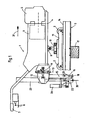
- An in Fig. 1 shown Nagelziehmaschine 1 has a track frame rollers 2 on a track 3 movable machine frame 4 with a motor 5 and a hydraulic system 6. At an end remote from the engine 5 operating handles 7 are provided with control devices 8.
- the machine frame 4 is mounted on a carriage 10 so as to be pivotable about an axis 9 running in the transverse direction of the track. This is in turn displaceable on a chassis frame 11 in the transverse direction of the track.
- a tool carrier 12 which is attached to the machine frame 4 pivotable about an axis 13.
- the axis 13 extends with respect to a track plane 14 in the normal direction.
- the tool holder 12 can be fixed by a locking device 19 in its pivoting movement about the axis 13.
- a normal to the track plane 14 extending support leg 15 is fixed, which is connected at a lower end 16 with a provided for resting on a threshold 17 support plate 18. This is in a - extending normal to the track plane 14 - longitudinal direction 21 of the support leg 15 relative to this slidably mounted and selectively connected by screws 20 with this.
- the clamping device 22 On the support leg 15 a - with a clamping device 22 connected - Zangenarme 28 is mounted vertically displaceable in a longitudinal direction 21 in a guide 24.
- the height adjustment of the clamping device 22 is effected by a
- the clamping device 22 has two pincer-shaped gripping elements 25 which are pivotable about a pincer axis 27 by a clamping drive 26.
- the clamping drive 26 is connected to the forceps carrier 28.
- the clamping device 22 and the support leg 15 are arranged one behind the other with respect to a machine longitudinal direction 31 defined by spaced apart flange wheels 2.
- the machine In use, the machine is placed by means of the operating handles 7 such that the clamping device 22 comes to rest with open gripping elements 25 via a nail head 29 of a rail nail 30.
- both gripper elements 25 are moved relative to one another with an optionally adjustable clamping force, whereby the nail head 29 is positively captured ( Fig. 2 ).
- the forceps support 28 With the subsequent activation of the height adjustment drive 23 - while pressing the support plate 18 on the threshold 17 - the forceps support 28 is raised together with the clamping device 22 and the clamping drive 26 while the rail nail 30 pulled out of the threshold 17.
- the clamping device 22 can be optimally adapted to the specific position of the rail nail 30 by pivoting the tool carrier 12 with a short-term solution of the locking device 19.
- the machine 1 In order to pull a rail nail 30 on the opposite side of the rail, only the machine 1 has to be slightly pivoted about the axis 9 until clamping device 22 and support plate 18 come to rest on the top rail.
- the gripping elements 25 By transverse displacement of the machine 1 by means of the carriage 10, the gripping elements 25 are centered on the rail nail 30 to be pulled.
- the forceps carrier 28 By lowering the forceps carrier 28, the initiation of the next drawing process takes place.
- clamp carrier 28 fixed to the support leg 15 and, for example, the support plate 18 by a Drive relative to the support leg 15 to adjust in the longitudinal direction 21, so as to pull a rail nail 30 from a threshold 17.
Landscapes
- Engineering & Computer Science (AREA)
- Mechanical Engineering (AREA)
- Architecture (AREA)
- Civil Engineering (AREA)
- Structural Engineering (AREA)
- Machines For Laying And Maintaining Railways (AREA)
- Confectionery (AREA)
- Finger-Pressure Massage (AREA)
- Bakery Products And Manufacturing Methods Therefor (AREA)
- Portable Nailing Machines And Staplers (AREA)
Description
- Die Erfindung betrifft eine Nagelziehmaschine zum Ziehen von Schienennägeln aus Schwellen eines Gleises, mit einer zur Anlage an einen Nagelkopf ausgebildete Greifelemente aufweisenden Klemmvorrichtung, wobei für die Bewegung der Greifelemente ein Klemmantrieb und für die Höhenverstellung der Klemmvorrichtung ein Höhenverstellantrieb vorgesehen ist.
-
US-A-3 883 118 beschreibt eine derartige Nagelziehmaschine in Form eines unter eigenem Antrieb gleisverfahrbaren Schienenfahrzeugs. Die zu beiden Seiten einer Schiene angeordneten Klemmvorrichtungen weisen Greifzangen auf, deren Abstand zueinander in Schienenlängsrichtung etwa der Länge einer Schwellenplatte entspricht. Ein auf der Maschine sitzenden Bediener muß die Klemmvorrichtung lediglich ungefähr über der betreffenden Einsatzstelle positionieren, um einen in diesem Schwellenplatten-Bereich gelegenen Nagel automatisch zu erfassen und herauszuziehen. -
DE 19 35 427 A1 offenbart eine von Hand verfahrbare Vorrichtung zum Ziehen von Federnägeln. Diese weisen jeweils eine Schlaufe auf, in die ein - auf einer Seite offener - Ziehhaken eingeführt wird, um den Federnagel aus der Schwelle zu ziehen. Das Einfädeln des Hakens erfolgt durch händisches Verschieben und Verschwenken der über der betreffenden Schiene positionierten Vorrichtung. - Eine weitere Maschine ist durch
EP 1 041 202 A1 bekannt, bei der die zangenförmigen Greifelemente in einem zylinderförmigen Rohr hochgezogen und dabei automatisch für ein Erfassen des Nagelkopfes zueinander bewegt werden. Dies hat allerdings den Nachteil, dass deformierte Nagelköpfe bzw. solche anderer Bauart nicht oder nur erschwert erfassbar sind. - Die Aufgabe der vorliegenden Erfindung liegt nun in der Schaffung einer Maschine der gattungsgemäßen Art mit verbesserter Bedienbarkeit bei gleichzeitig kompakter Bauweise.
- Erfindungsgemäß wird diese Aufgabe mit einer Maschine der eingangs genannten Art durch die im Kennzeichen des Hauptanspruches angeführten Merkmale gelöst.
- Mit dieser Ausbildung wird in vorteilhafter Weise eine besonders kompakte und daher leichte, aus Klemmvorrichtung und Stützfuß bestehende Einheit geschaffen, die sich durch ergonomisch günstige Bedienbarkeit und Handlichkeit auszeichnet, und zwar insbesondere beim Einsatz auf einer von Hand verfahrbaren Kleinmaschine. Ein weitere Vorteil besteht darin, dass die Bedienungsperson lediglich auf die richtige Platzierung bzw. Zentrierung der Klemmzange achten muss, wobei gleichzeitig und automatisch auch der Stützfuß in der korrekten Lage auf der Schwelle positioniert ist. Außerdem ist ein vollkommen problemloser und rascher Wechsel von der einen auf die benachbarte Schienenlängsseite möglich, ohne dass dazu irgendwelche Umrüst- oder Einstellungsarbeiten erforderlich wären.
- Weitere Vorteile und Ausbildungen der Erfindung ergeben sich aus den weiteren Ansprüchen und der Zeichnung.
- Im folgenden wird die Erfindung anhand von in der Zeichnung dargestellten Ausführungsbeispielen näher beschrieben.
- Es zeigen:
- Fig. 1
- eine Seitenansicht einer Nagelziehmaschine, und
- Fig. 2
- eine Detailansicht einer zum Erfassen eines Schienennagels ausgebildeten Klemmvorrichtung.
- Eine in
Fig. 1 dargestellte Nagelziehmaschine 1 weist einen durch Spurkranzrollen 2 auf einem Gleis 3 verfahrbaren Maschinenrahmen 4 mit einem Motor 5 und einer Hydraulikanlage 6 auf. An einem vom Motor 5 distanzierten Ende sind Bedienungshandgriffe 7 mit Steuereinrichtungen 8 vorgesehen. Der Maschinenrahmen 4 ist um eine in Gleisquerrichtung verlaufende Achse 9 verschwenkbar auf einem Schlitten 10 gelagert. Dieser ist seinerseits auf einem Fahrgestellrahmen 11 in Gleisquerrichtung verschiebbar. - Zwischen dem Schlitten 10 und den Bedienungshandgriffen 7 befindet sich ein Werkzeugträger 12, der um eine Achse 13 verschwenkbar am Maschinenrahmen 4 befestigt ist. Die Achse 13 verläuft bezüglich einer Gleisebene 14 in normaler Richtung. Der Werkzeugträger 12 ist durch eine Arretiereinrichtung 19 in seiner Schwenkbewegung um die Achse 13 fixierbar.
- Wie auch in
Fig. 2 ersichtlich, ist am Werkzeugträger 12 ein normal zur Gleisebene 14 verlaufender Stützfuß 15 befestigt, der an einem unteren Ende 16 mit einem zur Auflage auf einer Schwelle 17 vorgesehenen Stützteller 18 verbunden ist. Dieser ist in einer - normal zur Gleisebene 14 verlaufenden - Längsrichtung 21 des Stützfußes 15 relativ zu diesem verschiebbar gelagert und wahlweise durch Schrauben 20 mit diesem verbindbar. - Auf dem Stützfuß 15 ist ein - mit einer Klemmvorrichtung 22 verbundener - Zangenträger 28 in einer Führung 24 in Längsrichtung 21 höhenverschiebbar gelagert. Die Höhenverstellung der Klemmvorrichtung 22 erfolgt durch einen am Werkzeugträger 12 befestigten Höhenverstellantrieb 23. Die Klemmvorrichtung 22 weist zwei zangenförmige Greifelemente 25 auf, die durch einen Klemmantrieb 26 um eine Zangenachse 27 verschwenkbar sind. Der Klemmantrieb 26 ist mit dem Zangenträger 28 verbunden. Die Klemmvorrichtung 22 und der Stützfuß 15 sind bezüglich einer - durch voneinander distanzierte Spurkranzrollen 2 definierten - Maschinenlängsrichtung 31 hintereinander angeordnet.
- Im Arbeitseinsatz wird die Maschine mit Hilfe der Bedienungshandgriffe 7 derart platziert, dass die Klemmvorrichtung 22 mit geöffneten Greifelementen 25 über einen Nagelkopf 29 eines Schienennagels 30 zu liegen kommt. Unter Beaufschlagung des Klemmantriebes 26 werden beide Greifelemente 25 mit einer wahlweise einstellbaren Klemmkraft zueinander bewegt, wodurch der Nagelkopf 29 formschlüssig erfasst wird (
Fig. 2 ). Mit der darauf folgenden Aktivierung des Höhenverstellantriebes 23 wird - unter Anpressung des Stütztellers 18 auf die Schwelle 17 - der Zangenträger 28 mitsamt der Klemmvorrichtung 22 und dem Klemmantrieb 26 angehoben und dabei der Schienennagel 30 aus der Schwelle 17 gezogen. - Im Falle von schrägliegenden Schwellen 17 kann unter kurzzeitiger Lösung der Arretiereinrichtung 19 die Klemmvorrichtung 22 durch Schwenkung des Werkzeugträgers 12 optimal an die spezielle Lage des Schienennagels 30 angepasst werden. Um einen Schienennagel 30 auch an der gegenüberliegenden Schienenseite ziehen zu können, muss lediglich die Maschine 1 geringfügig um die Achse 9 geschwenkt werden, bis Klemmvorrichtung 22 und Stützteller 18 über der Schienenoberkante zu liegen kommen. Durch Querverschieben der Maschine 1 mit Hilfe des Schlittens 10 sind die Greifelemente 25 über dem zu ziehenden Schienennagel 30 zentrierbar. Durch Absenken des Zangenträgers 28 erfolgt die Einleitung des nächsten Ziehvorganges.
- Alternativ besteht natürlich auch die Möglichkeit, den Zangenträger 28 fix am Stützfuß 15 anzuordnen und beispielsweise den Stützteller 18 durch einen Antrieb relativ zum Stützfuß 15 in Längsrichtung 21 zu verstellen, um damit einen Schienenagel 30 aus einer Schwelle 17 zu ziehen.
Claims (4)
- Nagelziehmaschine zum Ziehen von Schienennägeln (30) aus Schwellen (17) eines Gleises (3), mit einer zur Anlage an einen Nagelkopf (29) ausgebildete Greifelemente (25) aufweisenden Klemmvorrichtung (22), wobei für die Bewegung der Greifelemente(25) ein Klemmantrieb (26) und für die Höhenverstellung der Klemmvorrichtung(22) ein Höhenverstellantrieb (23) vorgesehen ist, dadurch gekennzeichnet, dass die Klemmvorrichtung (22) mitsamt dem Klemmantrieb (26) auf einem zur Auflage auf einer Schwelle(17) vorgesehenen Stützfuß (15) höhenverstellbar gelagert ist und dass bezüglich einer- durch voneinander distanzierte Spurkranzrollen(2) definierten - Maschinenlängsrichtung (31) die Klemmvorrichtung (22) und der Stützfuß (15) hintereinander angeordnet sind, wobei der Stützfuß (15) von Bedienungshandgriffen (7) weiter distanziert ist als die Klemmvorrichtung (22), und die Klemmvorrichtung (22) und der Stützfuß (15) auf einem Werkzeugträger (12) befestigt sind, der auf einem durch die Spurkranzrollen(2) am Gleis(3) verfahrbaren Maschinenrahmen (4) gelagert ist, wobei der Maschinenrahmen (4) auf einem Schlitten gelagert ist, der auf einem Fahrgestellrahmen (11) in Gleisquerrichtung verschiebbar ist.
- Maschine nach Anspruch 1, dadurch gekennzeichnet, dass der Werkzeugträger (12) um eine Achse (13) verschwenkbar auf dem Maschinenrahmen (4) gelagert ist.
- Maschine nach Anspruch 2, dadurch gekennzeichnet, dass der Werkzeugträger (12) durch eine Arretiereinrichtung (19) in seiner Schwenkposition relativ zum Maschinenrahmen (4) arretierbar ist.
- Maschine nach Anspruch 1, dadurch gekennzeichnet, dass ein unteres Ende (16) des Stützfußes (15) als Stützteller (18) ausgebildet ist, der in einer Längsrichtung (21) des Stützfußes (15) relativ zu diesem verschiebbar gelagert und bezüglich der Verschieberichtung wahlweise mit diesem verbindbar ist.
Applications Claiming Priority (1)
| Application Number | Priority Date | Filing Date | Title |
|---|---|---|---|
| DE202004010216U DE202004010216U1 (de) | 2004-06-30 | 2004-06-30 | Nagelziehmaschine |
Publications (3)
| Publication Number | Publication Date |
|---|---|
| EP1612330A2 EP1612330A2 (de) | 2006-01-04 |
| EP1612330A3 EP1612330A3 (de) | 2006-08-30 |
| EP1612330B1 true EP1612330B1 (de) | 2009-08-12 |
Family
ID=32981607
Family Applications (1)
| Application Number | Title | Priority Date | Filing Date |
|---|---|---|---|
| EP05003012A Expired - Lifetime EP1612330B1 (de) | 2004-06-30 | 2005-02-12 | Nagelziehmaschine |
Country Status (5)
| Country | Link |
|---|---|
| US (1) | US20060000382A1 (de) |
| EP (1) | EP1612330B1 (de) |
| AT (1) | ATE439473T1 (de) |
| DE (2) | DE202004010216U1 (de) |
| RU (1) | RU2005115648A (de) |
Families Citing this family (5)
| Publication number | Priority date | Publication date | Assignee | Title |
|---|---|---|---|---|
| ES2336517B8 (es) * | 2007-07-30 | 2011-07-28 | Francisco Ortiz Aranega | Maquina de extraccion de clavos. |
| ATE489326T1 (de) † | 2008-09-15 | 2010-12-15 | Markus Erich Riedl | Regalbediengerät-greifer und verfahren zum betreiben des regalbediengerät-greifers |
| DE202012007818U1 (de) * | 2012-08-16 | 2012-09-24 | Robel Bahnbaumaschinen Gmbh | Händisch verschiebbare Maschine für die Gleiserhaltung |
| US9637867B2 (en) | 2014-08-05 | 2017-05-02 | Good Earth Tools, Inc. | Spike claw puller and method of manufacture thereof |
| FR3076840B1 (fr) * | 2018-01-15 | 2020-01-03 | Matisa Materiel Industriel S.A. | Dispositif d'arrimage d'un appareil de voie ferree ameliore |
Family Cites Families (7)
| Publication number | Priority date | Publication date | Assignee | Title |
|---|---|---|---|---|
| US1893719A (en) * | 1930-07-09 | 1933-01-10 | Nordberg Manufacturing Co | Spike puller |
| US3249334A (en) * | 1962-02-27 | 1966-05-03 | Nordberg Manufacturing Co | Hydraulic spike puller |
| US3336001A (en) * | 1966-02-14 | 1967-08-15 | Robert M Barton | Pin puller |
| DE1935427C3 (de) * | 1969-07-11 | 1980-10-16 | Franz Plasser Bahnbaumaschinen- Industriegesellschaft Mbh, Wien | Hydrostatisches Nagelziehgerät |
| US3883118A (en) * | 1974-06-03 | 1975-05-13 | Southern Railway Co | Spike pulling mechanism |
| US4078766A (en) * | 1977-04-11 | 1978-03-14 | Saurwein Albert C | Powered nail extractor |
| US6098960A (en) * | 1999-03-31 | 2000-08-08 | Framatome Connectors Usa, Inc. | Hydraulic spike puller |
-
2004
- 2004-06-30 DE DE202004010216U patent/DE202004010216U1/de not_active Expired - Lifetime
-
2005
- 2005-02-12 EP EP05003012A patent/EP1612330B1/de not_active Expired - Lifetime
- 2005-02-12 DE DE502005007878T patent/DE502005007878D1/de not_active Expired - Fee Related
- 2005-02-12 AT AT05003012T patent/ATE439473T1/de not_active IP Right Cessation
- 2005-05-24 RU RU2005115648/02A patent/RU2005115648A/ru unknown
- 2005-06-22 US US11/159,075 patent/US20060000382A1/en not_active Abandoned
Also Published As
| Publication number | Publication date |
|---|---|
| DE502005007878D1 (de) | 2009-09-24 |
| RU2005115648A (ru) | 2006-11-27 |
| DE202004010216U1 (de) | 2004-09-09 |
| US20060000382A1 (en) | 2006-01-05 |
| ATE439473T1 (de) | 2009-08-15 |
| EP1612330A3 (de) | 2006-08-30 |
| EP1612330A2 (de) | 2006-01-04 |
Similar Documents
| Publication | Publication Date | Title |
|---|---|---|
| AT400689B (de) | Bohrmaschine | |
| EP2607021B1 (de) | Abzugsvorrichtung für Radsatzlager von Schienenfahrzeugen | |
| AT12802U1 (de) | Haltevorrichtung für einen baulaser | |
| EP1612330B1 (de) | Nagelziehmaschine | |
| DE202020002598U1 (de) | Biegemaschine zum Biegen eines Werkstücks aus Flachmaterial und Steuereinheit für eine solche Biegemaschine | |
| EP1790521A1 (de) | Verstellbare Sitzhalterung für einen Fahrgastsitz | |
| AT508755A4 (de) | Stopfmaschine mit einer zusatzhebeeinrichtung | |
| EP3201395B1 (de) | Schweissaggregat | |
| EP1736602A1 (de) | Schweissmaschine zum Verschweissen von Schienen eines Gleises | |
| EP3411527B1 (de) | Schweissaggregat zum verschweissen von schienen eines gleises | |
| DE2457272A1 (de) | Vorrichtung zur einstellung von schwellen eines eisenbahngleises rechtwinklig zu demselben (travelage) und zur ausrichtung derselben auf die gleisachse (equerrage) | |
| EP4339062B1 (de) | Verfahren zum zentrieren bzw. auslenken eines kupplungskopfs eines schienenfahrzeugs, sowie eine abstützvorrichtung zur durchführung des verfahrens | |
| EP4497515A1 (de) | Biegemaschine zum biegen von flachmaterial und verfahren zum zubiegen eines stehfalzes an einem flachtmaterial unter verwendung der biegemaschine | |
| DE60223987T2 (de) | Stanzmaschine | |
| EP0195994A2 (de) | Rohrgassen-Manipulator zum Hochdruckabschlämmmen von Wärmetauschern | |
| EP3673112B1 (de) | Verfahren und vorrichtung zur erneuerung von schwellen eines gleises | |
| DE4108993A1 (de) | Hilfshebevorrichtung fuer eisenbahnschienen | |
| DE19653806B4 (de) | Maschine zur Durchführung von Schienenschweißungen | |
| DE2933602A1 (de) | Maschine zum gleichzeitigen anbringen zweier klemmen an einer schwelle zu beiden seiten einer schiene | |
| DE20305569U1 (de) | Vorrichtung zur Montage von Schienenklemmen | |
| EP2130624B1 (de) | Richtbank zum Richten von Containern | |
| DE856449C (de) | Hebelgeraet zum Ausziehen von Stahlfeder-Schienennaegeln aus Eisenbahnschwellen | |
| EP0918106B1 (de) | Klemmzange zum Abziehen von Schienen | |
| EP2610033B1 (de) | Haltebackeneinheit | |
| EP4527713A1 (de) | Verfahren zum entkuppeln eines kupplungskopfs einer kupplung eines schienenfahrzeugs, sowie eine vorrichtung zur durchführung des verfahrens |
Legal Events
| Date | Code | Title | Description |
|---|---|---|---|
| PUAI | Public reference made under article 153(3) epc to a published international application that has entered the european phase |
Free format text: ORIGINAL CODE: 0009012 |
|
| AK | Designated contracting states |
Kind code of ref document: A2 Designated state(s): AT BE BG CH CY CZ DE DK EE ES FI FR GB GR HU IE IS IT LI LT LU MC NL PL PT RO SE SI SK TR |
|
| AX | Request for extension of the european patent |
Extension state: AL BA HR LV MK YU |
|
| PUAL | Search report despatched |
Free format text: ORIGINAL CODE: 0009013 |
|
| AK | Designated contracting states |
Kind code of ref document: A3 Designated state(s): AT BE BG CH CY CZ DE DK EE ES FI FR GB GR HU IE IS IT LI LT LU MC NL PL PT RO SE SI SK TR |
|
| AX | Request for extension of the european patent |
Extension state: AL BA HR LV MK YU |
|
| 17P | Request for examination filed |
Effective date: 20070228 |
|
| 17Q | First examination report despatched |
Effective date: 20070411 |
|
| AKX | Designation fees paid |
Designated state(s): AT BE BG CH CY CZ DE DK EE ES FI FR GB GR HU IE IS IT LI LT LU MC NL PL PT RO SE SI SK TR |
|
| GRAP | Despatch of communication of intention to grant a patent |
Free format text: ORIGINAL CODE: EPIDOSNIGR1 |
|
| GRAS | Grant fee paid |
Free format text: ORIGINAL CODE: EPIDOSNIGR3 |
|
| GRAA | (expected) grant |
Free format text: ORIGINAL CODE: 0009210 |
|
| AK | Designated contracting states |
Kind code of ref document: B1 Designated state(s): AT BE BG CH CY CZ DE DK EE ES FI FR GB GR HU IE IS IT LI LT LU MC NL PL PT RO SE SI SK TR |
|
| REG | Reference to a national code |
Ref country code: GB Ref legal event code: FG4D Free format text: NOT ENGLISH |
|
| REG | Reference to a national code |
Ref country code: CH Ref legal event code: EP |
|
| REG | Reference to a national code |
Ref country code: IE Ref legal event code: FG4D |
|
| REF | Corresponds to: |
Ref document number: 502005007878 Country of ref document: DE Date of ref document: 20090924 Kind code of ref document: P |
|
| REG | Reference to a national code |
Ref country code: EE Ref legal event code: FG4A Ref document number: E003699 Country of ref document: EE Effective date: 20091020 |
|
| PG25 | Lapsed in a contracting state [announced via postgrant information from national office to epo] |
Ref country code: SE Free format text: LAPSE BECAUSE OF FAILURE TO SUBMIT A TRANSLATION OF THE DESCRIPTION OR TO PAY THE FEE WITHIN THE PRESCRIBED TIME-LIMIT Effective date: 20090812 Ref country code: IS Free format text: LAPSE BECAUSE OF FAILURE TO SUBMIT A TRANSLATION OF THE DESCRIPTION OR TO PAY THE FEE WITHIN THE PRESCRIBED TIME-LIMIT Effective date: 20091212 Ref country code: FI Free format text: LAPSE BECAUSE OF FAILURE TO SUBMIT A TRANSLATION OF THE DESCRIPTION OR TO PAY THE FEE WITHIN THE PRESCRIBED TIME-LIMIT Effective date: 20090812 Ref country code: ES Free format text: LAPSE BECAUSE OF FAILURE TO SUBMIT A TRANSLATION OF THE DESCRIPTION OR TO PAY THE FEE WITHIN THE PRESCRIBED TIME-LIMIT Effective date: 20091123 |
|
| NLV1 | Nl: lapsed or annulled due to failure to fulfill the requirements of art. 29p and 29m of the patents act | ||
| PG25 | Lapsed in a contracting state [announced via postgrant information from national office to epo] |
Ref country code: SI Free format text: LAPSE BECAUSE OF FAILURE TO SUBMIT A TRANSLATION OF THE DESCRIPTION OR TO PAY THE FEE WITHIN THE PRESCRIBED TIME-LIMIT Effective date: 20090812 Ref country code: PL Free format text: LAPSE BECAUSE OF FAILURE TO SUBMIT A TRANSLATION OF THE DESCRIPTION OR TO PAY THE FEE WITHIN THE PRESCRIBED TIME-LIMIT Effective date: 20090812 Ref country code: NL Free format text: LAPSE BECAUSE OF FAILURE TO SUBMIT A TRANSLATION OF THE DESCRIPTION OR TO PAY THE FEE WITHIN THE PRESCRIBED TIME-LIMIT Effective date: 20090812 |
|
| REG | Reference to a national code |
Ref country code: IE Ref legal event code: FD4D |
|
| PG25 | Lapsed in a contracting state [announced via postgrant information from national office to epo] |
Ref country code: BG Free format text: LAPSE BECAUSE OF FAILURE TO SUBMIT A TRANSLATION OF THE DESCRIPTION OR TO PAY THE FEE WITHIN THE PRESCRIBED TIME-LIMIT Effective date: 20091112 Ref country code: PT Free format text: LAPSE BECAUSE OF FAILURE TO SUBMIT A TRANSLATION OF THE DESCRIPTION OR TO PAY THE FEE WITHIN THE PRESCRIBED TIME-LIMIT Effective date: 20091212 |
|
| PG25 | Lapsed in a contracting state [announced via postgrant information from national office to epo] |
Ref country code: IE Free format text: LAPSE BECAUSE OF FAILURE TO SUBMIT A TRANSLATION OF THE DESCRIPTION OR TO PAY THE FEE WITHIN THE PRESCRIBED TIME-LIMIT Effective date: 20090812 Ref country code: CZ Free format text: LAPSE BECAUSE OF FAILURE TO SUBMIT A TRANSLATION OF THE DESCRIPTION OR TO PAY THE FEE WITHIN THE PRESCRIBED TIME-LIMIT Effective date: 20090812 Ref country code: RO Free format text: LAPSE BECAUSE OF FAILURE TO SUBMIT A TRANSLATION OF THE DESCRIPTION OR TO PAY THE FEE WITHIN THE PRESCRIBED TIME-LIMIT Effective date: 20090812 Ref country code: DK Free format text: LAPSE BECAUSE OF FAILURE TO SUBMIT A TRANSLATION OF THE DESCRIPTION OR TO PAY THE FEE WITHIN THE PRESCRIBED TIME-LIMIT Effective date: 20090812 |
|
| PG25 | Lapsed in a contracting state [announced via postgrant information from national office to epo] |
Ref country code: SK Free format text: LAPSE BECAUSE OF FAILURE TO SUBMIT A TRANSLATION OF THE DESCRIPTION OR TO PAY THE FEE WITHIN THE PRESCRIBED TIME-LIMIT Effective date: 20090812 |
|
| PLBE | No opposition filed within time limit |
Free format text: ORIGINAL CODE: 0009261 |
|
| STAA | Information on the status of an ep patent application or granted ep patent |
Free format text: STATUS: NO OPPOSITION FILED WITHIN TIME LIMIT |
|
| 26N | No opposition filed |
Effective date: 20100517 |
|
| BERE | Be: lapsed |
Owner name: ROBEL BAHNBAUMASCHINEN G.M.B.H. Effective date: 20100228 |
|
| REG | Reference to a national code |
Ref country code: CH Ref legal event code: PL |
|
| GBPC | Gb: european patent ceased through non-payment of renewal fee |
Effective date: 20100212 |
|
| PG25 | Lapsed in a contracting state [announced via postgrant information from national office to epo] |
Ref country code: MC Free format text: LAPSE BECAUSE OF NON-PAYMENT OF DUE FEES Effective date: 20100301 Ref country code: GR Free format text: LAPSE BECAUSE OF FAILURE TO SUBMIT A TRANSLATION OF THE DESCRIPTION OR TO PAY THE FEE WITHIN THE PRESCRIBED TIME-LIMIT Effective date: 20091113 Ref country code: LI Free format text: LAPSE BECAUSE OF NON-PAYMENT OF DUE FEES Effective date: 20100228 Ref country code: CH Free format text: LAPSE BECAUSE OF NON-PAYMENT OF DUE FEES Effective date: 20100228 |
|
| REG | Reference to a national code |
Ref country code: FR Ref legal event code: ST Effective date: 20101029 |
|
| PG25 | Lapsed in a contracting state [announced via postgrant information from national office to epo] |
Ref country code: FR Free format text: LAPSE BECAUSE OF NON-PAYMENT OF DUE FEES Effective date: 20100301 |
|
| PG25 | Lapsed in a contracting state [announced via postgrant information from national office to epo] |
Ref country code: BE Free format text: LAPSE BECAUSE OF NON-PAYMENT OF DUE FEES Effective date: 20100228 Ref country code: DE Free format text: LAPSE BECAUSE OF NON-PAYMENT OF DUE FEES Effective date: 20100901 |
|
| PG25 | Lapsed in a contracting state [announced via postgrant information from national office to epo] |
Ref country code: GB Free format text: LAPSE BECAUSE OF NON-PAYMENT OF DUE FEES Effective date: 20100212 Ref country code: IT Free format text: LAPSE BECAUSE OF FAILURE TO SUBMIT A TRANSLATION OF THE DESCRIPTION OR TO PAY THE FEE WITHIN THE PRESCRIBED TIME-LIMIT Effective date: 20090812 |
|
| PG25 | Lapsed in a contracting state [announced via postgrant information from national office to epo] |
Ref country code: AT Free format text: LAPSE BECAUSE OF NON-PAYMENT OF DUE FEES Effective date: 20100212 |
|
| PG25 | Lapsed in a contracting state [announced via postgrant information from national office to epo] |
Ref country code: CY Free format text: LAPSE BECAUSE OF FAILURE TO SUBMIT A TRANSLATION OF THE DESCRIPTION OR TO PAY THE FEE WITHIN THE PRESCRIBED TIME-LIMIT Effective date: 20090812 |
|
| PG25 | Lapsed in a contracting state [announced via postgrant information from national office to epo] |
Ref country code: HU Free format text: LAPSE BECAUSE OF FAILURE TO SUBMIT A TRANSLATION OF THE DESCRIPTION OR TO PAY THE FEE WITHIN THE PRESCRIBED TIME-LIMIT Effective date: 20100213 Ref country code: LU Free format text: LAPSE BECAUSE OF NON-PAYMENT OF DUE FEES Effective date: 20100212 |
|
| PG25 | Lapsed in a contracting state [announced via postgrant information from national office to epo] |
Ref country code: TR Free format text: LAPSE BECAUSE OF FAILURE TO SUBMIT A TRANSLATION OF THE DESCRIPTION OR TO PAY THE FEE WITHIN THE PRESCRIBED TIME-LIMIT Effective date: 20090812 |
|
| PGFP | Annual fee paid to national office [announced via postgrant information from national office to epo] |
Ref country code: LT Payment date: 20130131 Year of fee payment: 9 Ref country code: EE Payment date: 20130221 Year of fee payment: 9 |
|
| REG | Reference to a national code |
Ref country code: LT Ref legal event code: MM4D Effective date: 20140212 |
|
| REG | Reference to a national code |
Ref country code: EE Ref legal event code: MM4A Ref document number: E003699 Country of ref document: EE Effective date: 20140228 |
|
| PG25 | Lapsed in a contracting state [announced via postgrant information from national office to epo] |
Ref country code: LT Free format text: LAPSE BECAUSE OF NON-PAYMENT OF DUE FEES Effective date: 20140212 Ref country code: EE Free format text: LAPSE BECAUSE OF NON-PAYMENT OF DUE FEES Effective date: 20140228 |