EP1612367A1 - Coulisse d'un rideau pour obscurcissement - Google Patents
Coulisse d'un rideau pour obscurcissement Download PDFInfo
- Publication number
- EP1612367A1 EP1612367A1 EP05253524A EP05253524A EP1612367A1 EP 1612367 A1 EP1612367 A1 EP 1612367A1 EP 05253524 A EP05253524 A EP 05253524A EP 05253524 A EP05253524 A EP 05253524A EP 1612367 A1 EP1612367 A1 EP 1612367A1
- Authority
- EP
- European Patent Office
- Prior art keywords
- black
- frame
- out blind
- frame section
- insert
- Prior art date
- Legal status (The legal status is an assumption and is not a legal conclusion. Google has not performed a legal analysis and makes no representation as to the accuracy of the status listed.)
- Granted
Links
- 208000003443 Unconsciousness Diseases 0.000 title claims abstract description 53
- 239000000463 material Substances 0.000 claims description 6
- 239000004745 nonwoven fabric Substances 0.000 claims description 2
- 239000000123 paper Substances 0.000 claims description 2
- 239000002759 woven fabric Substances 0.000 claims description 2
- 239000011248 coating agent Substances 0.000 description 3
- 238000000576 coating method Methods 0.000 description 3
- 238000010422 painting Methods 0.000 description 3
- 238000003780 insertion Methods 0.000 description 2
- 230000037431 insertion Effects 0.000 description 2
- 230000033001 locomotion Effects 0.000 description 2
- 230000007246 mechanism Effects 0.000 description 2
- 238000005096 rolling process Methods 0.000 description 2
- 238000005452 bending Methods 0.000 description 1
- 230000005540 biological transmission Effects 0.000 description 1
- 230000000694 effects Effects 0.000 description 1
- 230000002452 interceptive effect Effects 0.000 description 1
- 238000004519 manufacturing process Methods 0.000 description 1
- 238000000034 method Methods 0.000 description 1
- 239000003973 paint Substances 0.000 description 1
- 239000012858 resilient material Substances 0.000 description 1
Images


Classifications
-
- E—FIXED CONSTRUCTIONS
- E06—DOORS, WINDOWS, SHUTTERS, OR ROLLER BLINDS IN GENERAL; LADDERS
- E06B—FIXED OR MOVABLE CLOSURES FOR OPENINGS IN BUILDINGS, VEHICLES, FENCES OR LIKE ENCLOSURES IN GENERAL, e.g. DOORS, WINDOWS, BLINDS, GATES
- E06B9/00—Screening or protective devices for wall or similar openings, with or without operating or securing mechanisms; Closures of similar construction
- E06B9/24—Screens or other constructions affording protection against light, especially against sunshine; Similar screens for privacy or appearance; Slat blinds
- E06B9/40—Roller blinds
-
- E—FIXED CONSTRUCTIONS
- E06—DOORS, WINDOWS, SHUTTERS, OR ROLLER BLINDS IN GENERAL; LADDERS
- E06B—FIXED OR MOVABLE CLOSURES FOR OPENINGS IN BUILDINGS, VEHICLES, FENCES OR LIKE ENCLOSURES IN GENERAL, e.g. DOORS, WINDOWS, BLINDS, GATES
- E06B9/00—Screening or protective devices for wall or similar openings, with or without operating or securing mechanisms; Closures of similar construction
- E06B9/24—Screens or other constructions affording protection against light, especially against sunshine; Similar screens for privacy or appearance; Slat blinds
- E06B9/40—Roller blinds
- E06B9/42—Parts or details of roller blinds, e.g. suspension devices, blind boxes
-
- E—FIXED CONSTRUCTIONS
- E06—DOORS, WINDOWS, SHUTTERS, OR ROLLER BLINDS IN GENERAL; LADDERS
- E06B—FIXED OR MOVABLE CLOSURES FOR OPENINGS IN BUILDINGS, VEHICLES, FENCES OR LIKE ENCLOSURES IN GENERAL, e.g. DOORS, WINDOWS, BLINDS, GATES
- E06B9/00—Screening or protective devices for wall or similar openings, with or without operating or securing mechanisms; Closures of similar construction
- E06B9/56—Operating, guiding or securing devices or arrangements for roll-type closures; Spring drums; Tape drums; Counterweighting arrangements therefor
- E06B9/58—Guiding devices
- E06B9/582—Means to increase gliss, light, sound or thermal insulation
Definitions
- the present invention relates to a frame section of a frame for a black-out blind assembly, in particular for reducing the transmission of light through the blind assembly.
- blinds for architectural openings. These blinds are used to cover openings, such as windows, to cover the opening and prevent ingress of any light. Examples of such blinds are described in US 2,354,489, US 5,117,892, DE 1 127 555 and DE 1 705 816.
- the blinds themselves can be sufficiently opaque to produce the desired effect, there is a problem that light can be reflected within the frame supporting the blind, such that this light travels around the side of the blind.
- the prior art proposes coating or painting inside surfaces of the frame of the black-out blind.
- the process of painting or coating the components in this way is undesirably complicated and expensive.
- the present invention recognises this problem and has an object to at least reduce the problem.
- the present invention it becomes a simple matter to prevent stray light from being reflected around the sides of the black-out blind.
- the separately manufactured insert can easily be inserted into the frame section.
- the insert is a sheet form extending between first and second parallel edges and is deformed so as to extend from the first edge adjacent the inner wall around the inside of the channel section to the second edge adjacent the outer wall.
- the insert By providing the insert as a sheet of appropriate width, it becomes very simple and inexpensive to manufacture the insert. Assembly of the frame section is not difficult, because it is only necessary to deform the sheet appropriately to fit it into the channel section.
- the inner and outer walls are provided with respective supports for receiving the first and second edges of the insert.
- the insert is easily and securely held in place within the channel section.
- the supports can include protrusions extending into the recess of the channel section so as to prevent the edges of the insert moving outwardly of the channel section.
- the supports need not in themselves fix the edges of the insert to the inner and outer walls. By preventing the edges from moving outwardly of the channel section, the insert is effectively held securely in place. This is because it extends around the inside of the channel section and, hence, as a whole, cannot move such that its edges move inwardly of the channel section.
- the supports can define respective openings facing inwardly of the recess of the channel section for receiving the edges of the insert.
- the openings can prevent the edges not only moving outwardly of the channel section, but also from moving away from the inner and outer walls.
- the supports can form elongate channels.
- edges of the insert fit into the elongate channels so as to secure them in place with respect to the inner and outer walls.
- the insert is at least partly resilient such that, once inserted in the recess of the channel section, the insert presses outwardly against the inner, outer and side walls.
- the insert is preferably a black material. It may be made of a non-woven material, paper, woven fabric, non-woven fabric, extruded flat film, extruded film in shape, etc.
- Frame sections of the present invention may be used for the sides of frames where a rolled black-out blind is unrolled from one end to the other along the length of the sides.
- a frame section can be arranged to receive an edge of a sheet forming a black-out blind, the edge sliding along the channel section as the black-out blind is moved between open and closed positions.
- Frame sections can also be used for ends of the frame.
- the frame section can be arranged to receive the rolled sheet forming a black-out blind, the sheet being unrolled from and rolled into the frame section as the black-out blind is moved between open and closed positions.
- a black-out blind will generally have a predefined thickness
- the end part of the frame in which the blind is rolled and unrolled there is a problem of light reflection.
- the end part has to have a sufficiently large recess to accommodate a fully rolled black-out blind. As a result, when the blind is unrolled, there is a large space within the recess around which light can be reflected.
- the present invention provides a very effective arrangement for overcoming this problem.
- the frame section is arranged to receive a rolled sheet
- the frame section further includes a rotatable support at each of two ends of the frame section for supporting therebetween a rolled sheet forming a black-out blind.
- a black-out blind assembly including a frame having at least one frame section as described above, together with a black-out blind moveable within the frame.
- the present invention is described with reference to an embodiment of a black-out blind assembly for a window opening, but can, of course, be used with any architectural opening. Indeed, it is described with reference to a blind which unrolls from the top of the frame. It will be appreciated that the frame can be positioned in any orientation and the black-out blind deployed in any appropriate direction.
- a black-out blind assembly 4 As illustrated in Figure 1, within a window frame 2 is mounted a black-out blind assembly 4.
- the black-out blind assembly 4 includes a head rail 6 mounted at the top of the frame 2 and two side guides 8 and 10 which extend respectively from each end of the head rail 6 along opposite sides of the frame 2.
- a black-out blind 12 may be deployed downwardly from the head rail 6 with its two opposing edges contained within channel sections of the side guides 8 and 10.
- a hand rail 14 is provided to enable a user to move the black-out blind up or down.
- the black-out blind 12 is opaque such that, once fully deployed with the hand rail 14 at the bottom of the frame 2, the black-out blind assembly prevents light from travelling past the frame 2.
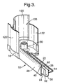
- FIGs 2, 3 and 4 illustrate further details of the side guide 10 and head rail 6 in the top left hand corner of the frame illustrated in Figure 1.
- the side guide 10 has an inner wall 20, on the inside face of the blind assembly 4, an outer wall 22, on the outside face of the blind assembly 4, and a side wall 24 from which these two generally parallel walls extend.
- the inner, outer and side walls form a channel section 26.
- the channel section 26 defines an elongate recess along which an edge of the black-out blind may slide up and down (as illustrated in Figure 1).
- an insert 30 is provided within the channel section 26.
- the insert 30 has a light absorbing substantially non-reflective surface and is, for instance, matt black.
- the insert 30 could be pre-formed of any suitable material for insertion into the channel section 26.
- the insert 30 is formed as an elongate sheet extending between a first edge 32 and a second edge 34. The sheet is merely deformed in the manner of bending or folding to insert it into the channel section 26.
- the first edge 32 is positioned adjacent the inner wall 20 whilst the second edge 34 is positioned adjacent the outer wall 22.
- the sheet then extends around the periphery of the channel section 26 providing the required light absorbing properties without interfering with the sliding motion of the edge of the black-out blind in the channel section 26.
- the sheet as a resilient member, it will inherently be biassed outwardly and, hence, conform to the inner profile of the channel section 26.
- the insert 30 is a black non-woven relatively resilient material.
- the inner wall 26 and outer wall 22 are provided with respective flanges 40 and 42 which extend towards one another and inwardly with respect to the channel section 26.
- These flanges 40 and 42 form supports for the edges 32 and 34 of the insert 30.
- flange 40 prevents the edge 32 from moving outwardly of the channel section and flange 42 prevents the edge 34 from moving outwardly of the channel section.
- the insert 30 is held securely in place within the channel section 26.
- the side guide 8 has a similar form and is provided with a corresponding insert.
- the head rail 6 also has a similar arrangement with an inner wall 120 on the inside of the frame 2 and a generally parallel outer wall 122 on the outside of the frame 2.
- a side wall 124 joins the inner wall 120 and outer wall 122, but, as compared with the side guide 10, these walls form a channel section 126 which has a partially circular cross section as compared with the more rectangular cross section of the channel section 26.
- each end cap 16, 18 is provided at each respective end of the guide rail 6.
- an inner portion of each end cap 16, 18 is provided with a support 60 on which a roll of black-out blind may be rotatably mounted.
- the blind assembly may additionally be provided with mechanisms for retracting the black-out blind by re-rolling it or, indeed, mechanisms for motorised operation of the blind.
- an insert 130 is provided within the recess of the channel section 126.
- the insert 130 is light absorbing and substantially non-reflective.
- the insert 130 could be pre-formed for insertion and constructed of any suitable material.
- the insert 130 has a sheet form extending from a first edge 132 to a second edge 134. The first edge is positioned adjacent the inner wall 120 and the second edge is positioned adjacent the outer wall 122.
- the insert extends along substantially all of the depth of the inner and outer walls 20 and 22.
- the insert it is not always necessary for the insert to extend up the entire wall.
- the second edge 134 of the insert 130 extends only as far as the innermost part of the outer wall 122.
- the insert 130 is preferably at least partly resilient. In this way, as illustrated, the insert 130 is naturally biassed so as to conform to the inner surface of the channel section 126.
- the inner wall 120 is provided with a flange 140 which projects inwardly of the channel section 126. This provides a step against which the first edge 132 of the insert 130 abuts.
- the flange 140 thus forms a support which prevents the first edge 132 from moving outwardly of the channel section 126.
- the outer wall 122 is formed with an inwardly facing elongate channel 142 into which the second edge 134 of the insert 130 is mounted.
- the elongate channel 142 provides a support for preventing the second edge 134 for moving outwardly of the channel section 126.
- the insert 130 is thus easily held in place with the channel section 126.
- the insert 130 does not interfere with rolling or unrolling of the black-out blind and yet still provides the necessary properties for preventing or at least reducing reflection of light.
- the supports for the edges of the inserts can be provided in other ways using any suitable form of rib, flange, groove, etc.
Landscapes
- Engineering & Computer Science (AREA)
- Structural Engineering (AREA)
- Architecture (AREA)
- Civil Engineering (AREA)
- Blinds (AREA)
- Operating, Guiding And Securing Of Roll- Type Closing Members (AREA)
Priority Applications (1)
| Application Number | Priority Date | Filing Date | Title |
|---|---|---|---|
| EP05253524A EP1612367B1 (fr) | 2004-06-30 | 2005-06-08 | Coulisse d'un rideau pour obscurcissement |
Applications Claiming Priority (2)
| Application Number | Priority Date | Filing Date | Title |
|---|---|---|---|
| EP04253931 | 2004-06-30 | ||
| EP05253524A EP1612367B1 (fr) | 2004-06-30 | 2005-06-08 | Coulisse d'un rideau pour obscurcissement |
Publications (2)
| Publication Number | Publication Date |
|---|---|
| EP1612367A1 true EP1612367A1 (fr) | 2006-01-04 |
| EP1612367B1 EP1612367B1 (fr) | 2007-08-01 |
Family
ID=35512692
Family Applications (1)
| Application Number | Title | Priority Date | Filing Date |
|---|---|---|---|
| EP05253524A Expired - Lifetime EP1612367B1 (fr) | 2004-06-30 | 2005-06-08 | Coulisse d'un rideau pour obscurcissement |
Country Status (5)
| Country | Link |
|---|---|
| US (1) | US20060000559A1 (fr) |
| EP (1) | EP1612367B1 (fr) |
| AT (1) | ATE368794T1 (fr) |
| AU (1) | AU2005202749B2 (fr) |
| DE (1) | DE602005001812T2 (fr) |
Families Citing this family (25)
| Publication number | Priority date | Publication date | Assignee | Title |
|---|---|---|---|---|
| WO2008002342A2 (fr) * | 2006-06-27 | 2008-01-03 | Wayne-Dalton Corp. | Ensemble rideau coupe-vent ayant un système de glissière de bordure et des caractéristiques de fixation à galet et barre de verrouillage |
| FR2909408A1 (fr) * | 2006-11-30 | 2008-06-06 | Bubendorff Sa | Coulisse de guidage pour element de fermeture et/ou d'occultation |
| EP2150671B1 (fr) * | 2007-04-26 | 2016-04-20 | VKR Holding A/S | Dispositif pour moustiquaire comprenant des moyens pour monter des rails latéraux et procédé de montage d'un tel dispositif pour moustiquaire |
| WO2008131757A1 (fr) * | 2007-04-26 | 2008-11-06 | Vkr Holding A/S | Dispositif de criblage à pièce terminale avec arbre de rouleau intégré |
| GB201021041D0 (en) * | 2010-12-13 | 2011-01-26 | Fourds Ltd | Screen assembly |
| US20120193038A1 (en) * | 2011-01-27 | 2012-08-02 | Comfortex Corporation | Window shade assembly and side channel therefor having light-absorbing surface |
| AT513942B1 (de) * | 2013-01-22 | 2017-11-15 | Htp High Tech Plastics Gmbh | Vorrichtung zur Abdeckung einer Sichtöffnung |
| USD789116S1 (en) | 2014-12-09 | 2017-06-13 | Hunter Douglas Inc. | Sample deck for selecting a covering for an architectural opening |
| US10604998B2 (en) | 2015-02-13 | 2020-03-31 | Hunter Douglas Inc. | Shading display and sample |
| USD878103S1 (en) | 2015-09-01 | 2020-03-17 | Vertilux Limited | Roller shade cassette cover |
| USD982351S1 (en) | 2015-09-01 | 2023-04-04 | Vertilux Limited | Roller shade cassette cover |
| US10774585B2 (en) | 2017-03-31 | 2020-09-15 | Hunter Douglas Inc | Perimeter light blockout system |
| DE102017111625A1 (de) * | 2017-05-29 | 2018-11-29 | Hunter Douglas Industries Switzerland Gmbh | Verdunkelungsvorrichtung |
| US20190284873A1 (en) * | 2018-02-15 | 2019-09-19 | Dagan Benzur | Integrated system and a method for installing an integrated system |
| USD885084S1 (en) | 2018-04-20 | 2020-05-26 | Vertilux Limited | Roller shade cassette cover |
| USD920004S1 (en) | 2018-04-20 | 2021-05-25 | Vertilux Limited | Roller shade cassette cover |
| USD866221S1 (en) | 2018-04-20 | 2019-11-12 | Vertilux Limited | Valance |
| USD955140S1 (en) * | 2019-08-22 | 2022-06-21 | Bandalux Industrial, S.A. | Box roller shade assembly |
| USD955141S1 (en) * | 2019-08-22 | 2022-06-21 | Bandalux Industrial, S.A. | Box roller shade assembly |
| USD954467S1 (en) | 2019-10-22 | 2022-06-14 | Vertilux Limited | Side channel |
| USD970254S1 (en) | 2020-03-23 | 2022-11-22 | Vertilux Limited | Round clutch core guard |
| US11332974B2 (en) | 2020-04-03 | 2022-05-17 | Vertilux Limited | Bottom rail bar connectable to a shade in different operative orientations |
| USD940477S1 (en) | 2020-05-19 | 2022-01-11 | Vertilux Limited | Oval bottomrail for a shade structure |
| US11814897B2 (en) | 2021-06-26 | 2023-11-14 | Vertilux Limited | Operating assembly and system for a roller shade |
| WO2024091799A1 (fr) * | 2022-10-26 | 2024-05-02 | Hunter Douglas Inc. | Revêtement éclairé de structure architecturale |
Citations (6)
| Publication number | Priority date | Publication date | Assignee | Title |
|---|---|---|---|---|
| US2354489A (en) * | 1942-04-07 | 1944-07-25 | Thomas T Tucker | Black-out means |
| DE1705816U (de) * | 1955-02-19 | 1955-08-25 | Ehage Rollofabrik Erich Hinnen | Fuehrungsschiene mit dichtungsborde fuer verdunklungsrollos. |
| DE1127555B (de) * | 1959-04-11 | 1962-04-12 | Herbert Reppert | Verdunklungseinrichtung |
| GB1020785A (en) * | 1963-02-08 | 1966-02-23 | Artistic Blind Company Ltd | Improvements in or relating to blinds |
| US4649981A (en) * | 1985-03-07 | 1987-03-17 | Appropriate Technology Corporation | Edge seal for fabric covers |
| US5117892A (en) * | 1990-06-22 | 1992-06-02 | Murray Alan C | Window shade track construction |
Family Cites Families (7)
| Publication number | Priority date | Publication date | Assignee | Title |
|---|---|---|---|---|
| US1882982A (en) * | 1930-11-25 | 1932-10-18 | August J Schmiedeskamp | Rolling screen retaining means |
| US2325992A (en) * | 1942-01-07 | 1943-08-03 | John C Wirthman | Black-out device |
| US4357978A (en) * | 1980-06-02 | 1982-11-09 | Keller Products, Inc. | Roller shade seal system |
| US4419982A (en) * | 1982-05-10 | 1983-12-13 | Eckels Robert E | Magnetic edge seal for solar collector film |
| US5601134A (en) * | 1995-03-23 | 1997-02-11 | Rite-Hite Corporation | Retainer assembly for roll-up door |
| US5647421A (en) * | 1995-06-06 | 1997-07-15 | Hunter Douglas Inc. | Dual shape assembly |
| US6666251B2 (en) * | 2001-01-31 | 2003-12-23 | Doris M. Ikle | Energy saving window shade system |
-
2005
- 2005-06-08 EP EP05253524A patent/EP1612367B1/fr not_active Expired - Lifetime
- 2005-06-08 AT AT05253524T patent/ATE368794T1/de active
- 2005-06-08 DE DE602005001812T patent/DE602005001812T2/de not_active Expired - Lifetime
- 2005-06-23 AU AU2005202749A patent/AU2005202749B2/en not_active Expired
- 2005-06-29 US US11/172,010 patent/US20060000559A1/en not_active Abandoned
Patent Citations (6)
| Publication number | Priority date | Publication date | Assignee | Title |
|---|---|---|---|---|
| US2354489A (en) * | 1942-04-07 | 1944-07-25 | Thomas T Tucker | Black-out means |
| DE1705816U (de) * | 1955-02-19 | 1955-08-25 | Ehage Rollofabrik Erich Hinnen | Fuehrungsschiene mit dichtungsborde fuer verdunklungsrollos. |
| DE1127555B (de) * | 1959-04-11 | 1962-04-12 | Herbert Reppert | Verdunklungseinrichtung |
| GB1020785A (en) * | 1963-02-08 | 1966-02-23 | Artistic Blind Company Ltd | Improvements in or relating to blinds |
| US4649981A (en) * | 1985-03-07 | 1987-03-17 | Appropriate Technology Corporation | Edge seal for fabric covers |
| US5117892A (en) * | 1990-06-22 | 1992-06-02 | Murray Alan C | Window shade track construction |
Also Published As
| Publication number | Publication date |
|---|---|
| EP1612367B1 (fr) | 2007-08-01 |
| US20060000559A1 (en) | 2006-01-05 |
| ATE368794T1 (de) | 2007-08-15 |
| DE602005001812D1 (de) | 2007-09-13 |
| AU2005202749A1 (en) | 2006-01-19 |
| DE602005001812T2 (de) | 2008-05-15 |
| AU2005202749B2 (en) | 2010-09-02 |
Similar Documents
| Publication | Publication Date | Title |
|---|---|---|
| EP1612367B1 (fr) | Coulisse d'un rideau pour obscurcissement | |
| US20180044977A1 (en) | Rolling door construction for controlling air leakage | |
| EP3529448B1 (fr) | Ensemble de support | |
| CA2764793A1 (fr) | Profile a verrouiller sur un panneau et systeme de panneaux | |
| EP2395194A1 (fr) | Système et procédé pour bloquer la lumière | |
| US8002342B2 (en) | Blind cover positioning structure | |
| PL209071B1 (pl) | Zestaw drzwiowy | |
| EP3319825B1 (fr) | Ensemble de protection de fenêtre ou de porte pour un véhicule | |
| EP4575172A1 (fr) | Pare-soleil à cordon et élément de vitrage | |
| KR20170000381U (ko) | 합성수지와 금속재질을 이용한 복합창호 | |
| WO2000026494A1 (fr) | Portes et fenetres coulissantes | |
| KR101618580B1 (ko) | 안전창호 | |
| JP6983564B2 (ja) | スクリーンの固定構造およびスクリーン装置 | |
| KR102614371B1 (ko) | 창호용 가이드 홈 마감 장치 | |
| KR200401750Y1 (ko) | 창호용 필링피스 | |
| US20220153095A1 (en) | Window shading apparatus having installation width adjustment function | |
| JP7657674B2 (ja) | スライドパネルの取付構造、カバー部材、及びスライドパネルの設置方法 | |
| JP2001227265A (ja) | 窓サッシ用スクリーン装置 | |
| CN224130852U (zh) | 一种车用卷帘防水结构及车辆尾箱 | |
| KR102909129B1 (ko) | 프레임리스 폴딩 도어용 프레임 | |
| JP7773870B2 (ja) | 障子及び建具 | |
| ITFE20080009A1 (it) | Sistema di tenuta al passaggio dell'aria, al rumore, al vento, antieffrazione e miglioramento dell'isolamento termico e acustico nei sistemi di tapparelle avvolgibili e relative guide di scorrimento e battute perimetrali su finestre e porte finestre | |
| NL2016894B1 (en) | Window or door covering assembly | |
| EP4689341A1 (fr) | Élément terminal appliqué sur le bord inférieur de la feuille souple d'un volet roulant et volet roulant utilisant ledit élément terminal | |
| JPS6233908Y2 (fr) |
Legal Events
| Date | Code | Title | Description |
|---|---|---|---|
| PUAI | Public reference made under article 153(3) epc to a published international application that has entered the european phase |
Free format text: ORIGINAL CODE: 0009012 |
|
| AK | Designated contracting states |
Kind code of ref document: A1 Designated state(s): AT BE BG CH CY CZ DE DK EE ES FI FR GB GR HU IE IS IT LI LT LU MC NL PL PT RO SE SI SK TR |
|
| AX | Request for extension of the european patent |
Extension state: AL BA HR LV MK YU |
|
| 17P | Request for examination filed |
Effective date: 20060607 |
|
| AKX | Designation fees paid |
Designated state(s): AT BE BG CH CY CZ DE DK EE ES FI FR GB GR HU IE IS IT LI LT LU MC NL PL PT RO SE SI SK TR |
|
| GRAP | Despatch of communication of intention to grant a patent |
Free format text: ORIGINAL CODE: EPIDOSNIGR1 |
|
| GRAS | Grant fee paid |
Free format text: ORIGINAL CODE: EPIDOSNIGR3 |
|
| GRAA | (expected) grant |
Free format text: ORIGINAL CODE: 0009210 |
|
| AK | Designated contracting states |
Kind code of ref document: B1 Designated state(s): AT BE BG CH CY CZ DE DK EE ES FI FR GB GR HU IE IS IT LI LT LU MC NL PL PT RO SE SI SK TR |
|
| REG | Reference to a national code |
Ref country code: GB Ref legal event code: FG4D |
|
| REG | Reference to a national code |
Ref country code: CH Ref legal event code: EP |
|
| REG | Reference to a national code |
Ref country code: IE Ref legal event code: FG4D |
|
| REF | Corresponds to: |
Ref document number: 602005001812 Country of ref document: DE Date of ref document: 20070913 Kind code of ref document: P |
|
| PG25 | Lapsed in a contracting state [announced via postgrant information from national office to epo] |
Ref country code: ES Free format text: LAPSE BECAUSE OF FAILURE TO SUBMIT A TRANSLATION OF THE DESCRIPTION OR TO PAY THE FEE WITHIN THE PRESCRIBED TIME-LIMIT Effective date: 20071112 Ref country code: BG Free format text: LAPSE BECAUSE OF FAILURE TO SUBMIT A TRANSLATION OF THE DESCRIPTION OR TO PAY THE FEE WITHIN THE PRESCRIBED TIME-LIMIT Effective date: 20071101 Ref country code: LT Free format text: LAPSE BECAUSE OF FAILURE TO SUBMIT A TRANSLATION OF THE DESCRIPTION OR TO PAY THE FEE WITHIN THE PRESCRIBED TIME-LIMIT Effective date: 20070801 Ref country code: IS Free format text: LAPSE BECAUSE OF FAILURE TO SUBMIT A TRANSLATION OF THE DESCRIPTION OR TO PAY THE FEE WITHIN THE PRESCRIBED TIME-LIMIT Effective date: 20071201 Ref country code: FI Free format text: LAPSE BECAUSE OF FAILURE TO SUBMIT A TRANSLATION OF THE DESCRIPTION OR TO PAY THE FEE WITHIN THE PRESCRIBED TIME-LIMIT Effective date: 20070801 |
|
| REG | Reference to a national code |
Ref country code: CH Ref legal event code: PL |
|
| PG25 | Lapsed in a contracting state [announced via postgrant information from national office to epo] |
Ref country code: LI Free format text: LAPSE BECAUSE OF FAILURE TO SUBMIT A TRANSLATION OF THE DESCRIPTION OR TO PAY THE FEE WITHIN THE PRESCRIBED TIME-LIMIT Effective date: 20070801 Ref country code: PL Free format text: LAPSE BECAUSE OF FAILURE TO SUBMIT A TRANSLATION OF THE DESCRIPTION OR TO PAY THE FEE WITHIN THE PRESCRIBED TIME-LIMIT Effective date: 20070801 Ref country code: CH Free format text: LAPSE BECAUSE OF FAILURE TO SUBMIT A TRANSLATION OF THE DESCRIPTION OR TO PAY THE FEE WITHIN THE PRESCRIBED TIME-LIMIT Effective date: 20070801 |
|
| EN | Fr: translation not filed | ||
| PG25 | Lapsed in a contracting state [announced via postgrant information from national office to epo] |
Ref country code: BE Free format text: LAPSE BECAUSE OF FAILURE TO SUBMIT A TRANSLATION OF THE DESCRIPTION OR TO PAY THE FEE WITHIN THE PRESCRIBED TIME-LIMIT Effective date: 20070801 |
|
| PG25 | Lapsed in a contracting state [announced via postgrant information from national office to epo] |
Ref country code: DK Free format text: LAPSE BECAUSE OF FAILURE TO SUBMIT A TRANSLATION OF THE DESCRIPTION OR TO PAY THE FEE WITHIN THE PRESCRIBED TIME-LIMIT Effective date: 20070801 Ref country code: GR Free format text: LAPSE BECAUSE OF FAILURE TO SUBMIT A TRANSLATION OF THE DESCRIPTION OR TO PAY THE FEE WITHIN THE PRESCRIBED TIME-LIMIT Effective date: 20071102 |
|
| PG25 | Lapsed in a contracting state [announced via postgrant information from national office to epo] |
Ref country code: PT Free format text: LAPSE BECAUSE OF FAILURE TO SUBMIT A TRANSLATION OF THE DESCRIPTION OR TO PAY THE FEE WITHIN THE PRESCRIBED TIME-LIMIT Effective date: 20080102 Ref country code: SK Free format text: LAPSE BECAUSE OF FAILURE TO SUBMIT A TRANSLATION OF THE DESCRIPTION OR TO PAY THE FEE WITHIN THE PRESCRIBED TIME-LIMIT Effective date: 20070801 Ref country code: CZ Free format text: LAPSE BECAUSE OF FAILURE TO SUBMIT A TRANSLATION OF THE DESCRIPTION OR TO PAY THE FEE WITHIN THE PRESCRIBED TIME-LIMIT Effective date: 20070801 |
|
| PLBE | No opposition filed within time limit |
Free format text: ORIGINAL CODE: 0009261 |
|
| STAA | Information on the status of an ep patent application or granted ep patent |
Free format text: STATUS: NO OPPOSITION FILED WITHIN TIME LIMIT |
|
| PG25 | Lapsed in a contracting state [announced via postgrant information from national office to epo] |
Ref country code: SE Free format text: LAPSE BECAUSE OF FAILURE TO SUBMIT A TRANSLATION OF THE DESCRIPTION OR TO PAY THE FEE WITHIN THE PRESCRIBED TIME-LIMIT Effective date: 20071101 Ref country code: RO Free format text: LAPSE BECAUSE OF FAILURE TO SUBMIT A TRANSLATION OF THE DESCRIPTION OR TO PAY THE FEE WITHIN THE PRESCRIBED TIME-LIMIT Effective date: 20070801 |
|
| 26N | No opposition filed |
Effective date: 20080506 |
|
| PG25 | Lapsed in a contracting state [announced via postgrant information from national office to epo] |
Ref country code: FR Free format text: LAPSE BECAUSE OF FAILURE TO SUBMIT A TRANSLATION OF THE DESCRIPTION OR TO PAY THE FEE WITHIN THE PRESCRIBED TIME-LIMIT Effective date: 20080328 |
|
| PG25 | Lapsed in a contracting state [announced via postgrant information from national office to epo] |
Ref country code: MC Free format text: LAPSE BECAUSE OF NON-PAYMENT OF DUE FEES Effective date: 20080630 |
|
| PG25 | Lapsed in a contracting state [announced via postgrant information from national office to epo] |
Ref country code: IE Free format text: LAPSE BECAUSE OF NON-PAYMENT OF DUE FEES Effective date: 20080609 Ref country code: EE Free format text: LAPSE BECAUSE OF FAILURE TO SUBMIT A TRANSLATION OF THE DESCRIPTION OR TO PAY THE FEE WITHIN THE PRESCRIBED TIME-LIMIT Effective date: 20070801 |
|
| PG25 | Lapsed in a contracting state [announced via postgrant information from national office to epo] |
Ref country code: SI Free format text: LAPSE BECAUSE OF FAILURE TO SUBMIT A TRANSLATION OF THE DESCRIPTION OR TO PAY THE FEE WITHIN THE PRESCRIBED TIME-LIMIT Effective date: 20070801 |
|
| PG25 | Lapsed in a contracting state [announced via postgrant information from national office to epo] |
Ref country code: CY Free format text: LAPSE BECAUSE OF FAILURE TO SUBMIT A TRANSLATION OF THE DESCRIPTION OR TO PAY THE FEE WITHIN THE PRESCRIBED TIME-LIMIT Effective date: 20070801 |
|
| PG25 | Lapsed in a contracting state [announced via postgrant information from national office to epo] |
Ref country code: HU Free format text: LAPSE BECAUSE OF FAILURE TO SUBMIT A TRANSLATION OF THE DESCRIPTION OR TO PAY THE FEE WITHIN THE PRESCRIBED TIME-LIMIT Effective date: 20080202 Ref country code: LU Free format text: LAPSE BECAUSE OF NON-PAYMENT OF DUE FEES Effective date: 20080608 |
|
| PG25 | Lapsed in a contracting state [announced via postgrant information from national office to epo] |
Ref country code: TR Free format text: LAPSE BECAUSE OF FAILURE TO SUBMIT A TRANSLATION OF THE DESCRIPTION OR TO PAY THE FEE WITHIN THE PRESCRIBED TIME-LIMIT Effective date: 20070801 |
|
| PGFP | Annual fee paid to national office [announced via postgrant information from national office to epo] |
Ref country code: IT Payment date: 20190620 Year of fee payment: 15 Ref country code: NL Payment date: 20190612 Year of fee payment: 15 Ref country code: DE Payment date: 20190528 Year of fee payment: 15 |
|
| PGFP | Annual fee paid to national office [announced via postgrant information from national office to epo] |
Ref country code: AT Payment date: 20190528 Year of fee payment: 15 Ref country code: GB Payment date: 20190605 Year of fee payment: 15 |
|
| REG | Reference to a national code |
Ref country code: DE Ref legal event code: R119 Ref document number: 602005001812 Country of ref document: DE |
|
| REG | Reference to a national code |
Ref country code: NL Ref legal event code: MM Effective date: 20200701 |
|
| REG | Reference to a national code |
Ref country code: AT Ref legal event code: MM01 Ref document number: 368794 Country of ref document: AT Kind code of ref document: T Effective date: 20200608 |
|
| GBPC | Gb: european patent ceased through non-payment of renewal fee |
Effective date: 20200608 |
|
| PG25 | Lapsed in a contracting state [announced via postgrant information from national office to epo] |
Ref country code: GB Free format text: LAPSE BECAUSE OF NON-PAYMENT OF DUE FEES Effective date: 20200608 Ref country code: NL Free format text: LAPSE BECAUSE OF NON-PAYMENT OF DUE FEES Effective date: 20200701 |
|
| PG25 | Lapsed in a contracting state [announced via postgrant information from national office to epo] |
Ref country code: DE Free format text: LAPSE BECAUSE OF NON-PAYMENT OF DUE FEES Effective date: 20210101 Ref country code: AT Free format text: LAPSE BECAUSE OF NON-PAYMENT OF DUE FEES Effective date: 20200608 |
|
| PG25 | Lapsed in a contracting state [announced via postgrant information from national office to epo] |
Ref country code: IT Free format text: LAPSE BECAUSE OF NON-PAYMENT OF DUE FEES Effective date: 20200608 |