EP1612836B1 - Méthode pour enlever un spécimen microscopique d'un substrat - Google Patents
Méthode pour enlever un spécimen microscopique d'un substrat Download PDFInfo
- Publication number
- EP1612836B1 EP1612836B1 EP20050076464 EP05076464A EP1612836B1 EP 1612836 B1 EP1612836 B1 EP 1612836B1 EP 20050076464 EP20050076464 EP 20050076464 EP 05076464 A EP05076464 A EP 05076464A EP 1612836 B1 EP1612836 B1 EP 1612836B1
- Authority
- EP
- European Patent Office
- Prior art keywords
- sample
- substrate
- beams
- cutting process
- probe
- Prior art date
- Legal status (The legal status is an assumption and is not a legal conclusion. Google has not performed a legal analysis and makes no representation as to the accuracy of the status listed.)
- Ceased
Links
- 238000000034 method Methods 0.000 title claims description 38
- 239000000758 substrate Substances 0.000 title claims description 38
- 239000000523 sample Substances 0.000 claims description 64
- 238000005520 cutting process Methods 0.000 claims description 30
- 230000001678 irradiating effect Effects 0.000 claims description 4
- 239000002245 particle Substances 0.000 claims description 4
- 238000010884 ion-beam technique Methods 0.000 description 20
- 235000012431 wafers Nutrition 0.000 description 9
- 238000004458 analytical method Methods 0.000 description 3
- 150000002500 ions Chemical group 0.000 description 3
- 238000004519 manufacturing process Methods 0.000 description 3
- 239000000463 material Substances 0.000 description 3
- 238000001465 metallisation Methods 0.000 description 3
- 239000002184 metal Substances 0.000 description 2
- 238000005549 size reduction Methods 0.000 description 2
- 238000002441 X-ray diffraction Methods 0.000 description 1
- 230000005540 biological transmission Effects 0.000 description 1
- 230000015572 biosynthetic process Effects 0.000 description 1
- 238000000151 deposition Methods 0.000 description 1
- 230000008021 deposition Effects 0.000 description 1
- 238000010894 electron beam technology Methods 0.000 description 1
- 230000008030 elimination Effects 0.000 description 1
- 238000003379 elimination reaction Methods 0.000 description 1
- 230000003628 erosive effect Effects 0.000 description 1
- 239000007789 gas Substances 0.000 description 1
- 230000005855 radiation Effects 0.000 description 1
- 239000004065 semiconductor Substances 0.000 description 1
Images

Classifications
-
- G—PHYSICS
- G01—MEASURING; TESTING
- G01N—INVESTIGATING OR ANALYSING MATERIALS BY DETERMINING THEIR CHEMICAL OR PHYSICAL PROPERTIES
- G01N1/00—Sampling; Preparing specimens for investigation
- G01N1/28—Preparing specimens for investigation including physical details of (bio-)chemical methods covered elsewhere, e.g. G01N33/50, C12Q
- G01N1/286—Preparing specimens for investigation including physical details of (bio-)chemical methods covered elsewhere, e.g. G01N33/50, C12Q involving mechanical work, e.g. chopping, disintegrating, compacting, homogenising
-
- G—PHYSICS
- G01—MEASURING; TESTING
- G01N—INVESTIGATING OR ANALYSING MATERIALS BY DETERMINING THEIR CHEMICAL OR PHYSICAL PROPERTIES
- G01N1/00—Sampling; Preparing specimens for investigation
- G01N1/28—Preparing specimens for investigation including physical details of (bio-)chemical methods covered elsewhere, e.g. G01N33/50, C12Q
- G01N1/32—Polishing; Etching
-
- H—ELECTRICITY
- H01—ELECTRIC ELEMENTS
- H01J—ELECTRIC DISCHARGE TUBES OR DISCHARGE LAMPS
- H01J37/00—Discharge tubes with provision for introducing objects or material to be exposed to the discharge, e.g. for the purpose of examination or processing thereof
- H01J37/30—Electron-beam or ion-beam tubes for localised treatment of objects
- H01J37/305—Electron-beam or ion-beam tubes for localised treatment of objects for casting, melting, evaporating, or etching
- H01J37/3053—Electron-beam or ion-beam tubes for localised treatment of objects for casting, melting, evaporating, or etching for evaporating or etching
- H01J37/3056—Electron-beam or ion-beam tubes for localised treatment of objects for casting, melting, evaporating, or etching for evaporating or etching for microworking, e. g. etching of gratings or trimming of electrical components
-
- H—ELECTRICITY
- H01—ELECTRIC ELEMENTS
- H01J—ELECTRIC DISCHARGE TUBES OR DISCHARGE LAMPS
- H01J2237/00—Discharge tubes exposing object to beam, e.g. for analysis treatment, etching, imaging
- H01J2237/30—Electron or ion beam tubes for processing objects
- H01J2237/317—Processing objects on a microscale
- H01J2237/31749—Focused ion beam
Definitions
- the invention pertains to a method for the removal of a microscopic sample from a substrate, comprising the steps of:
- a method such as this is employed in particular in the semiconductor industry, where samples of microscopic proportions are taken out of substrates such as wafers in order to facilitate analysis and/or further processing. These days, such samples have dimensions of the order of magnitude of 10 ⁇ m at a thickness of 100nm. A trend exists towards an even further size-reduction in the structures of interest, and, as a result hereof, a further size-reduction in the samples to be extracted.
- the analyses which are made of such microscopic samples can be carried out, for example, with the aid of a TEM (Transmission Electron Microscope), SEM (Scanning Electron Microscope), SIMS (Secondary Ion Mass Spectroscope) or with X-Ray analysis equipment.
- the further processing/manipulations can consist of, for example, making the sample thinner with the aid of an ion beam for the purposes of analysis with the aid of a TEM.
- a needle-shaped probe is moved by a manipulator to a position on a substrate where a sample is to be extracted.
- the sample is cut away from the substrate by removing material from two different directions with a focused ion-beam.
- the sample Prior to completely cutting the sample out of the substrate, the sample is adhered to the extremity of the probe by means of, for example, metal deposition. After the sample is completely cut away the sample adhered to the probe is moved to another position with the aid of the manipulator.
- part of the cutting process prior to commencing the adhesion process, part of the cutting process must first be performed. After all, the presence of the needle-shaped probe causes shadow-formation; the presence of the probe will render a portion of the substrate invisible to the ion-beam deployed. For that reason, it is necessary to first commence the cutting process and then only move the probe to the sample position upon completion of the cutting in that region of the substrate that will come to lie in the shadow of the sample holder. Only thereafter can the adhesion process be started, whereupon the cutting process can be recommenced in order to completely extract the sample.
- the US patent document US6538254 B discloses a method for fabrication of a micro-specimen comprising fixing the specimen to a probe and extracting and separating the micro-specimen from the specimen substrate.
- a first ion beam e.g. a projection ion beam
- a second ion beam e.g. a focused ion beam
- US2002/0050565 A discloses a method for fabrication of a micro-specimen comprising fixing the specimen to a probe and extracting and separating the micro-specimen from the specimen substrate.
- a first ion beam e.g. a projection ion beam
- a second ion beam e.g. a focused ion beam
- the method according to the invention is characterized in that the cutting process, during at least part of the duration of the cutting process, is carried out by two beams simultaneously.
- the sample is cut from the substrate by irradiating the substrate sequentially from two different directions.
- two different beams are used for this.
- the orientation of the substrate with respect to the radiation sources remains unchanged during the cutting process.
- a wedge-shaped cut will generally have to be made.
- a first cut is first made, whereupon the angle of incidence of the cutting beam with respect to the substrate is changed and a second cut is made. Altering the angle of incidence of the cutting beam usually occurs through changing the orientation of the substrate.
- these beams will generally subtend an angle with respect to one another. Because of this, the sample can be completely extracted without having to change the orientation of the substrate.
- the beam in, in general, the beam is positioned with respect to the substrate with the aid of deflecting means.
- the orientation of the beam varies hereby slightly with respect to the substrate.
- this change of angle cannot generally be used to cut out the sample all around.
- the beams intersect each other in the sample, a feat which is not easily achieved when the beams are deflected by deflection means that are placed outside the substrate.
- the adhesion process comprises irradiating with a beam.
- Adhering the sample to the probe with the aid of a beam can take place using a method known per se, whereby a metal deposition is applied, with the aid of, for example, an ion beam.
- This adhesion can be carried out using one of the beams with which, for at least part of the time, the cutting process is performed, but the beam can also be a different beam than the beams which perform the cutting.
- the beam with which the adhesion process is performed does not necessarily have to be of the same type as the type with which the cutting process is performed. It is conceivable that a beam of ions be used for cutting and a beam of photons or an electron beam be used for the adhesion process.
- the adhesion process and the cutting process overlap each other temporally.
- the aforementioned irradiation comprises irradiating with beams of electrically charged particles.
- a beam of electrically-charged particles in particular a beam of ions
- the application of a metal deposit with the aid of an ion beam is a method known per se .
- the irradiation with electrically charged particles can occur coincident with, for example, the presence of special gases, whereby, for example, the cutting-speed of the beam(s) can be increased or the application of a metal deposition becomes possible.
- Figure 1 schematically depicts a particle-optical device suited to the performance of the method according to the invention, equipped with two columns 11 and 12, each of which produces an ion beam 4 and 5, respectively.
- the particle-optical device comprises a vacuum chamber 10, a first column 11 - mounted on the vacuum chamber 10 - for the production of a first ion beam 4, a second column 12 - mounted on the vacuum chamber 10 - for the production of a second ion beam 5, control means 13 embodied to simultaneously operate columns 11 and 12, a probe 14 which can be manipulated, and a substrate carrier 15 which can be positioned.
- the vacuum chamber 10 is maintained, by means of (non-depicted) evacuation means, in vacuum or at least at a pressure significantly less than atmospheric pressure.
- the columns 11 and 12 are mounted to the vacuum chamber 10 at such an orientation that the ion beams 4 and 5 produced by these columns practically intersect each other.
- a substrate in the form of a wafer 2 placed on the positionable substrate carrier 15 is positioned with the aid of the positionable substrate carrier 15 in such a manner that a sample 1 which is to be extracted lies practically at the intersection of the two beams 4 and 5.
- the cutting process can commence hereafter.
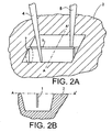
- Figures 2A and 2B schematically depict a substrate in the form of a wafer 2 from which a sample 1 is cut away by two beams 4 and 5.
- Figure 2A shows how sample 1 is cut away from wafer 2 by two ion beams 4 and 5 simultaneously. Because the two beams 4 and 5 subtend an angle with respect to each other, it is possible to cut out the sample 1 all around without the wafer 2 having to assume another orientation with respect to the columns 11 and 12 that produce the beams 4 and 5.
- a sample to be extracted will typically have dimensions of the order of magnitude of 10 ⁇ m (that is to say length perpendicular to line AA') and a thickness (that is to say dimension in the direction of line AA') of 100nm.
- Figure 2B shows a transverse cross-section according to line AA' depicted in figure 2A , whereby it can be clearly seen that the sample 1 is free at the lower surface from the wafer 2.
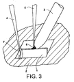
- Figure 3 schematically depicts a sample 1 that is being affixed at the extremity of the probe 3.
- the cutting process in the depicted situation is sufficiently progressed that no further shadow-effect of the probe 14 is to be feared.
- the needle-shaped extremity 3 of the probe 14, which can be manipulated, is moved to the position of the sample 1 to be extracted.
- the sample 1 is connected to the extremity 3 of probe 14 by irradiation with an ion beam 5, whereby a metal deposit 6 adheres the sample 1 to the probe 14.
- the remaining connection 7 between the sample 1 and the wafer 2 is removed with ion beam 4.
- the sample 1 that is adhered to the probe 14 can be taken away.
Landscapes
- Chemical & Material Sciences (AREA)
- Physics & Mathematics (AREA)
- Analytical Chemistry (AREA)
- Life Sciences & Earth Sciences (AREA)
- Health & Medical Sciences (AREA)
- Biochemistry (AREA)
- General Health & Medical Sciences (AREA)
- General Physics & Mathematics (AREA)
- Immunology (AREA)
- Pathology (AREA)
- Plasma & Fusion (AREA)
- Engineering & Computer Science (AREA)
- Sampling And Sample Adjustment (AREA)
Claims (5)
- Procédé pour le retrait d'un échantillon microscopique (1) d'un substrat (2) comprenant :. la mise en oeuvre d'un processus de découpage où le substrat (2) est irradié avec au moins deux faisceaux (4) de telle sorte que l'échantillon (1) est retiré du substrat (2) par découpage, et. la mise en oeuvre d'un processus d'adhésion où l'échantillon (1) est amené à adhérer à une sonde (3),caractérisé en ce que. le processus de découpage, pendant au moins une partie de la durée du processus de découpage, est mis en oeuvre par lesdits au moins deux faisceaux (4, 5) simultanément.
- Procédé selon la revendication 1 où, pendant le processus de découpage, l'orientation du substrat (2) par rapport aux moyens qui produisent les deux faisceaux (4, 5) reste inchangée.
- Procédé selon l'une des revendications précédentes où le processus d'adhésion comprend l'irradiation de l'échantillon (1) avec un faisceau (5).
- Procédé selon la revendication 3 où le processus d'adhésion et le processus de découpage se chevauchent dans le temps.
- Procédé selon l'une des revendications précédentes où l'irradiation comprend une radiation avec des faisceaux (4, 5) de particules électriquement chargées.
Priority Applications (1)
| Application Number | Priority Date | Filing Date | Title |
|---|---|---|---|
| EP20050076464 EP1612836B1 (fr) | 2004-07-01 | 2005-06-27 | Méthode pour enlever un spécimen microscopique d'un substrat |
Applications Claiming Priority (2)
| Application Number | Priority Date | Filing Date | Title |
|---|---|---|---|
| EP04076892 | 2004-07-01 | ||
| EP20050076464 EP1612836B1 (fr) | 2004-07-01 | 2005-06-27 | Méthode pour enlever un spécimen microscopique d'un substrat |
Publications (3)
| Publication Number | Publication Date |
|---|---|
| EP1612836A2 EP1612836A2 (fr) | 2006-01-04 |
| EP1612836A3 EP1612836A3 (fr) | 2009-01-14 |
| EP1612836B1 true EP1612836B1 (fr) | 2010-02-24 |
Family
ID=35107026
Family Applications (1)
| Application Number | Title | Priority Date | Filing Date |
|---|---|---|---|
| EP20050076464 Ceased EP1612836B1 (fr) | 2004-07-01 | 2005-06-27 | Méthode pour enlever un spécimen microscopique d'un substrat |
Country Status (1)
| Country | Link |
|---|---|
| EP (1) | EP1612836B1 (fr) |
Families Citing this family (2)
| Publication number | Priority date | Publication date | Assignee | Title |
|---|---|---|---|---|
| ATE439579T1 (de) | 2007-06-29 | 2009-08-15 | Fei Co | Verfahren zum befestigen einer probe an einem manipulator |
| EP2009420A1 (fr) * | 2007-06-29 | 2008-12-31 | FEI Company | Procédé de fixation d'un échantillon à un manipulateur |
Family Cites Families (4)
| Publication number | Priority date | Publication date | Assignee | Title |
|---|---|---|---|---|
| US5009743A (en) * | 1989-11-06 | 1991-04-23 | Gatan Incorporated | Chemically-assisted ion beam milling system for the preparation of transmission electron microscope specimens |
| JP2774884B2 (ja) | 1991-08-22 | 1998-07-09 | 株式会社日立製作所 | 試料の分離方法及びこの分離方法で得た分離試料の分析方法 |
| WO1999005506A1 (fr) * | 1997-07-22 | 1999-02-04 | Hitachi, Ltd. | Procede et dispositif de preparation d'echantillons |
| JP4178741B2 (ja) * | 2000-11-02 | 2008-11-12 | 株式会社日立製作所 | 荷電粒子線装置および試料作製装置 |
-
2005
- 2005-06-27 EP EP20050076464 patent/EP1612836B1/fr not_active Ceased
Also Published As
| Publication number | Publication date |
|---|---|
| EP1612836A2 (fr) | 2006-01-04 |
| EP1612836A3 (fr) | 2009-01-14 |
Similar Documents
| Publication | Publication Date | Title |
|---|---|---|
| US10283317B2 (en) | High throughput TEM preparation processes and hardware for backside thinning of cross-sectional view lamella | |
| EP1998356B1 (fr) | Préparation d'échantillon STEM in situ | |
| US7442924B2 (en) | Repetitive circumferential milling for sample preparation | |
| JP6366216B2 (ja) | Tem画像化用の薄い試料を作製する方法 | |
| EP1870691B1 (fr) | Préparation d'échantillon en vue planaire | |
| US7375325B2 (en) | Method for preparing a sample for electron microscopic examinations, and sample supports and transport holders used therefor | |
| US20060017016A1 (en) | Method for the removal of a microscopic sample from a substrate | |
| US6417512B1 (en) | Sample distortion removing method in thin piece forming | |
| KR20060092827A (ko) | 진공 챔버에서 샘플 형성 및 마이크로분석을 위한 방법 및장치 | |
| CN105103270A (zh) | 用于准备用于成像的样本的方法 | |
| JP2004087174A (ja) | イオンビーム装置およびイオンビーム加工方法 | |
| KR20180132546A (ko) | 평면 뷰 라멜라 제조를 위한 면상 기체-보조된 에칭 | |
| US7408178B2 (en) | Method for the removal of a microscopic sample from a substrate | |
| US20130001191A1 (en) | Redeposition technique for membrane attachment | |
| US5940678A (en) | Method of forming precisely cross-sectioned electron-transparent samples | |
| US7180061B2 (en) | Method for electron beam-initiated coating for application of transmission electron microscopy | |
| US7345289B2 (en) | Sample support prepared by semiconductor silicon process technique | |
| EP1612836A2 (fr) | Méthode pour enlever un spécimen microscopique d'un substrat | |
| JP2004179038A (ja) | 透過電子顕微鏡用試料の固定方法および試料台 | |
| KR20070016023A (ko) | 전자 현미경의 시료를 고정하기 위한 그리드 구조체 | |
| EP1612837B1 (fr) | Méthode pour prélever un échantillon microscopique d'un substrat | |
| KR20050041312A (ko) | 반도체 시료의 제조 방법 | |
| EP1436601B1 (fr) | Procede de separation et de retrait d'echantillons |
Legal Events
| Date | Code | Title | Description |
|---|---|---|---|
| PUAI | Public reference made under article 153(3) epc to a published international application that has entered the european phase |
Free format text: ORIGINAL CODE: 0009012 |
|
| 17P | Request for examination filed |
Effective date: 20050627 |
|
| AK | Designated contracting states |
Kind code of ref document: A2 Designated state(s): AT BE BG CH CY CZ DE DK EE ES FI FR GB GR HU IE IS IT LI LT LU MC NL PL PT RO SE SI SK TR |
|
| AX | Request for extension of the european patent |
Extension state: AL BA HR LV MK YU |
|
| PUAL | Search report despatched |
Free format text: ORIGINAL CODE: 0009013 |
|
| AK | Designated contracting states |
Kind code of ref document: A3 Designated state(s): AT BE BG CH CY CZ DE DK EE ES FI FR GB GR HU IE IS IT LI LT LU MC NL PL PT RO SE SI SK TR |
|
| AX | Request for extension of the european patent |
Extension state: AL BA HR LV MK YU |
|
| 17Q | First examination report despatched |
Effective date: 20090330 |
|
| AKX | Designation fees paid |
Designated state(s): AT BE BG CH CY CZ DE DK EE ES FI FR GB GR HU IE IS IT LI LT LU MC NL PL PT RO SE SI SK TR |
|
| GRAP | Despatch of communication of intention to grant a patent |
Free format text: ORIGINAL CODE: EPIDOSNIGR1 |
|
| GRAS | Grant fee paid |
Free format text: ORIGINAL CODE: EPIDOSNIGR3 |
|
| GRAA | (expected) grant |
Free format text: ORIGINAL CODE: 0009210 |
|
| AK | Designated contracting states |
Kind code of ref document: B1 Designated state(s): AT BE BG CH CY CZ DE DK EE ES FI FR GB GR HU IE IS IT LI LT LU MC NL PL PT RO SE SI SK TR |
|
| REG | Reference to a national code |
Ref country code: GB Ref legal event code: FG4D |
|
| REG | Reference to a national code |
Ref country code: CH Ref legal event code: EP |
|
| REG | Reference to a national code |
Ref country code: IE Ref legal event code: FG4D |
|
| REF | Corresponds to: |
Ref document number: 602005019498 Country of ref document: DE Date of ref document: 20100408 Kind code of ref document: P |
|
| REG | Reference to a national code |
Ref country code: NL Ref legal event code: VDEP Effective date: 20100224 |
|
| LTIE | Lt: invalidation of european patent or patent extension |
Effective date: 20100224 |
|
| PG25 | Lapsed in a contracting state [announced via postgrant information from national office to epo] |
Ref country code: PT Free format text: LAPSE BECAUSE OF FAILURE TO SUBMIT A TRANSLATION OF THE DESCRIPTION OR TO PAY THE FEE WITHIN THE PRESCRIBED TIME-LIMIT Effective date: 20100625 Ref country code: LT Free format text: LAPSE BECAUSE OF FAILURE TO SUBMIT A TRANSLATION OF THE DESCRIPTION OR TO PAY THE FEE WITHIN THE PRESCRIBED TIME-LIMIT Effective date: 20100224 Ref country code: IS Free format text: LAPSE BECAUSE OF FAILURE TO SUBMIT A TRANSLATION OF THE DESCRIPTION OR TO PAY THE FEE WITHIN THE PRESCRIBED TIME-LIMIT Effective date: 20100624 |
|
| PG25 | Lapsed in a contracting state [announced via postgrant information from national office to epo] |
Ref country code: SI Free format text: LAPSE BECAUSE OF FAILURE TO SUBMIT A TRANSLATION OF THE DESCRIPTION OR TO PAY THE FEE WITHIN THE PRESCRIBED TIME-LIMIT Effective date: 20100224 Ref country code: AT Free format text: LAPSE BECAUSE OF FAILURE TO SUBMIT A TRANSLATION OF THE DESCRIPTION OR TO PAY THE FEE WITHIN THE PRESCRIBED TIME-LIMIT Effective date: 20100224 Ref country code: FI Free format text: LAPSE BECAUSE OF FAILURE TO SUBMIT A TRANSLATION OF THE DESCRIPTION OR TO PAY THE FEE WITHIN THE PRESCRIBED TIME-LIMIT Effective date: 20100224 Ref country code: PL Free format text: LAPSE BECAUSE OF FAILURE TO SUBMIT A TRANSLATION OF THE DESCRIPTION OR TO PAY THE FEE WITHIN THE PRESCRIBED TIME-LIMIT Effective date: 20100224 |
|
| PG25 | Lapsed in a contracting state [announced via postgrant information from national office to epo] |
Ref country code: CY Free format text: LAPSE BECAUSE OF FAILURE TO SUBMIT A TRANSLATION OF THE DESCRIPTION OR TO PAY THE FEE WITHIN THE PRESCRIBED TIME-LIMIT Effective date: 20100224 Ref country code: BE Free format text: LAPSE BECAUSE OF FAILURE TO SUBMIT A TRANSLATION OF THE DESCRIPTION OR TO PAY THE FEE WITHIN THE PRESCRIBED TIME-LIMIT Effective date: 20100224 Ref country code: EE Free format text: LAPSE BECAUSE OF FAILURE TO SUBMIT A TRANSLATION OF THE DESCRIPTION OR TO PAY THE FEE WITHIN THE PRESCRIBED TIME-LIMIT Effective date: 20100224 Ref country code: ES Free format text: LAPSE BECAUSE OF FAILURE TO SUBMIT A TRANSLATION OF THE DESCRIPTION OR TO PAY THE FEE WITHIN THE PRESCRIBED TIME-LIMIT Effective date: 20100604 Ref country code: GR Free format text: LAPSE BECAUSE OF FAILURE TO SUBMIT A TRANSLATION OF THE DESCRIPTION OR TO PAY THE FEE WITHIN THE PRESCRIBED TIME-LIMIT Effective date: 20100525 Ref country code: SE Free format text: LAPSE BECAUSE OF FAILURE TO SUBMIT A TRANSLATION OF THE DESCRIPTION OR TO PAY THE FEE WITHIN THE PRESCRIBED TIME-LIMIT Effective date: 20100224 Ref country code: RO Free format text: LAPSE BECAUSE OF FAILURE TO SUBMIT A TRANSLATION OF THE DESCRIPTION OR TO PAY THE FEE WITHIN THE PRESCRIBED TIME-LIMIT Effective date: 20100224 Ref country code: NL Free format text: LAPSE BECAUSE OF FAILURE TO SUBMIT A TRANSLATION OF THE DESCRIPTION OR TO PAY THE FEE WITHIN THE PRESCRIBED TIME-LIMIT Effective date: 20100224 |
|
| PG25 | Lapsed in a contracting state [announced via postgrant information from national office to epo] |
Ref country code: CZ Free format text: LAPSE BECAUSE OF FAILURE TO SUBMIT A TRANSLATION OF THE DESCRIPTION OR TO PAY THE FEE WITHIN THE PRESCRIBED TIME-LIMIT Effective date: 20100224 Ref country code: SK Free format text: LAPSE BECAUSE OF FAILURE TO SUBMIT A TRANSLATION OF THE DESCRIPTION OR TO PAY THE FEE WITHIN THE PRESCRIBED TIME-LIMIT Effective date: 20100224 Ref country code: BG Free format text: LAPSE BECAUSE OF FAILURE TO SUBMIT A TRANSLATION OF THE DESCRIPTION OR TO PAY THE FEE WITHIN THE PRESCRIBED TIME-LIMIT Effective date: 20100524 |
|
| PLBE | No opposition filed within time limit |
Free format text: ORIGINAL CODE: 0009261 |
|
| STAA | Information on the status of an ep patent application or granted ep patent |
Free format text: STATUS: NO OPPOSITION FILED WITHIN TIME LIMIT |
|
| PG25 | Lapsed in a contracting state [announced via postgrant information from national office to epo] |
Ref country code: MC Free format text: LAPSE BECAUSE OF NON-PAYMENT OF DUE FEES Effective date: 20100630 Ref country code: DK Free format text: LAPSE BECAUSE OF FAILURE TO SUBMIT A TRANSLATION OF THE DESCRIPTION OR TO PAY THE FEE WITHIN THE PRESCRIBED TIME-LIMIT Effective date: 20100224 |
|
| REG | Reference to a national code |
Ref country code: CH Ref legal event code: PL |
|
| 26N | No opposition filed |
Effective date: 20101125 |
|
| PG25 | Lapsed in a contracting state [announced via postgrant information from national office to epo] |
Ref country code: IT Free format text: LAPSE BECAUSE OF FAILURE TO SUBMIT A TRANSLATION OF THE DESCRIPTION OR TO PAY THE FEE WITHIN THE PRESCRIBED TIME-LIMIT Effective date: 20100224 |
|
| PG25 | Lapsed in a contracting state [announced via postgrant information from national office to epo] |
Ref country code: LI Free format text: LAPSE BECAUSE OF NON-PAYMENT OF DUE FEES Effective date: 20100630 Ref country code: CH Free format text: LAPSE BECAUSE OF NON-PAYMENT OF DUE FEES Effective date: 20100630 Ref country code: IE Free format text: LAPSE BECAUSE OF NON-PAYMENT OF DUE FEES Effective date: 20100627 |
|
| PG25 | Lapsed in a contracting state [announced via postgrant information from national office to epo] |
Ref country code: HU Free format text: LAPSE BECAUSE OF FAILURE TO SUBMIT A TRANSLATION OF THE DESCRIPTION OR TO PAY THE FEE WITHIN THE PRESCRIBED TIME-LIMIT Effective date: 20100825 Ref country code: LU Free format text: LAPSE BECAUSE OF NON-PAYMENT OF DUE FEES Effective date: 20100627 |
|
| PG25 | Lapsed in a contracting state [announced via postgrant information from national office to epo] |
Ref country code: TR Free format text: LAPSE BECAUSE OF FAILURE TO SUBMIT A TRANSLATION OF THE DESCRIPTION OR TO PAY THE FEE WITHIN THE PRESCRIBED TIME-LIMIT Effective date: 20100224 |
|
| REG | Reference to a national code |
Ref country code: FR Ref legal event code: PLFP Year of fee payment: 12 |
|
| REG | Reference to a national code |
Ref country code: FR Ref legal event code: PLFP Year of fee payment: 13 |
|
| REG | Reference to a national code |
Ref country code: FR Ref legal event code: PLFP Year of fee payment: 14 |
|
| PGFP | Annual fee paid to national office [announced via postgrant information from national office to epo] |
Ref country code: DE Payment date: 20180612 Year of fee payment: 14 |
|
| PGFP | Annual fee paid to national office [announced via postgrant information from national office to epo] |
Ref country code: GB Payment date: 20180627 Year of fee payment: 14 |
|
| PGFP | Annual fee paid to national office [announced via postgrant information from national office to epo] |
Ref country code: FR Payment date: 20190510 Year of fee payment: 15 |
|
| REG | Reference to a national code |
Ref country code: DE Ref legal event code: R119 Ref document number: 602005019498 Country of ref document: DE |
|
| GBPC | Gb: european patent ceased through non-payment of renewal fee |
Effective date: 20190627 |
|
| PG25 | Lapsed in a contracting state [announced via postgrant information from national office to epo] |
Ref country code: DE Free format text: LAPSE BECAUSE OF NON-PAYMENT OF DUE FEES Effective date: 20200101 Ref country code: GB Free format text: LAPSE BECAUSE OF NON-PAYMENT OF DUE FEES Effective date: 20190627 |
|
| PG25 | Lapsed in a contracting state [announced via postgrant information from national office to epo] |
Ref country code: FR Free format text: LAPSE BECAUSE OF NON-PAYMENT OF DUE FEES Effective date: 20200630 |