EP1612929A2 - Motorreglungsvorrichtung - Google Patents
Motorreglungsvorrichtung Download PDFInfo
- Publication number
- EP1612929A2 EP1612929A2 EP05014076A EP05014076A EP1612929A2 EP 1612929 A2 EP1612929 A2 EP 1612929A2 EP 05014076 A EP05014076 A EP 05014076A EP 05014076 A EP05014076 A EP 05014076A EP 1612929 A2 EP1612929 A2 EP 1612929A2
- Authority
- EP
- European Patent Office
- Prior art keywords
- voltage
- current
- phase advance
- reactive current
- phase
- Prior art date
- Legal status (The legal status is an assumption and is not a legal conclusion. Google has not performed a legal analysis and makes no representation as to the accuracy of the status listed.)
- Granted
Links
Images







Classifications
-
- H—ELECTRICITY
- H02—GENERATION; CONVERSION OR DISTRIBUTION OF ELECTRIC POWER
- H02P—CONTROL OR REGULATION OF ELECTRIC MOTORS, ELECTRIC GENERATORS OR DYNAMO-ELECTRIC CONVERTERS; CONTROLLING TRANSFORMERS, REACTORS OR CHOKE COILS
- H02P29/00—Arrangements for regulating or controlling electric motors, appropriate for both AC and DC motors
- H02P29/02—Providing protection against overload without automatic interruption of supply
- H02P29/024—Detecting a fault condition, e.g. short circuit, locked rotor, open circuit or loss of load
- H02P29/026—Detecting a fault condition, e.g. short circuit, locked rotor, open circuit or loss of load the fault being a power fluctuation
-
- H—ELECTRICITY
- H02—GENERATION; CONVERSION OR DISTRIBUTION OF ELECTRIC POWER
- H02P—CONTROL OR REGULATION OF ELECTRIC MOTORS, ELECTRIC GENERATORS OR DYNAMO-ELECTRIC CONVERTERS; CONTROLLING TRANSFORMERS, REACTORS OR CHOKE COILS
- H02P21/00—Arrangements or methods for the control of electric machines by vector control, e.g. by control of field orientation
- H02P21/0085—Arrangements or methods for the control of electric machines by vector control, e.g. by control of field orientation specially adapted for high speeds, e.g. above nominal speed
- H02P21/0089—Arrangements or methods for the control of electric machines by vector control, e.g. by control of field orientation specially adapted for high speeds, e.g. above nominal speed using field weakening
-
- H—ELECTRICITY
- H02—GENERATION; CONVERSION OR DISTRIBUTION OF ELECTRIC POWER
- H02P—CONTROL OR REGULATION OF ELECTRIC MOTORS, ELECTRIC GENERATORS OR DYNAMO-ELECTRIC CONVERTERS; CONTROLLING TRANSFORMERS, REACTORS OR CHOKE COILS
- H02P21/00—Arrangements or methods for the control of electric machines by vector control, e.g. by control of field orientation
- H02P21/22—Current control, e.g. using a current control loop
-
- H—ELECTRICITY
- H02—GENERATION; CONVERSION OR DISTRIBUTION OF ELECTRIC POWER
- H02P—CONTROL OR REGULATION OF ELECTRIC MOTORS, ELECTRIC GENERATORS OR DYNAMO-ELECTRIC CONVERTERS; CONTROLLING TRANSFORMERS, REACTORS OR CHOKE COILS
- H02P25/00—Arrangements or methods for the control of AC motors characterised by the kind of AC motor or by structural details
- H02P25/02—Arrangements or methods for the control of AC motors characterised by the kind of AC motor or by structural details characterised by the kind of motor
- H02P25/022—Synchronous motors
- H02P25/03—Synchronous motors with brushless excitation
-
- H—ELECTRICITY
- H02—GENERATION; CONVERSION OR DISTRIBUTION OF ELECTRIC POWER
- H02P—CONTROL OR REGULATION OF ELECTRIC MOTORS, ELECTRIC GENERATORS OR DYNAMO-ELECTRIC CONVERTERS; CONTROLLING TRANSFORMERS, REACTORS OR CHOKE COILS
- H02P6/00—Arrangements for controlling synchronous motors or other dynamo-electric motors using electronic commutation dependent on the rotor position; Electronic commutators therefor
- H02P6/14—Electronic commutators
- H02P6/15—Controlling commutation time
- H02P6/153—Controlling commutation time wherein the commutation is advanced from position signals phase in function of the speed
Definitions
- the present invention relates to a motor control device and, more particularly, to control of a synchronous motor according to a DQ transformation.
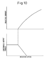
- Fig. 10 is a characteristic diagram showing a relationship between a reactive current and a rotation speed and a relationship between a continuous output torque and a rotation speed, according to a conventional reactive current control.
- a reactive current that is required for rotation at the assumed minimum voltage must be supplied.
- a continuous output torque decreases rapidly in a high-speed area.
- Fig. 11 and Fig. 12 are characteristic diagrams showing a relationship between the phase advance and a rotation speed and a relationship between instantaneous maximum torque and a rotation speed, according to conventional phase advancement.
- Fig. 11 shows an example of a phase advance control that is suitable when the voltage is low. The phase advance is controlled constantly regardless of voltage. Therefore, the torque decreases when the voltage is high.
- Fig. 12 shows an example of a phase advance control that is suitable when a voltage is high. Because the phase advance is controlled constantly regardless of the voltage, the torque decreases when the voltage is low.
- This motor control device changes a base speed (starting speed) at which a d-phase current is started to be passed based on voltage command values that are output as functions of d-phase and q-phase current command values in a high-speed rotation area. Based on this, a maximum current in the d-phase and a minimum current in the d-phase are adjusted to indirectly adjust a d-phase current command value, thereby decreasing the influence of a variation in the power supply voltage.
- the motor control device described in Japanese Patent Application Unexamined Publication No. 2003-52199 uses characteristics of the inside of the controller to change a base rotation speed at which a d-phase current is started to be passed based on voltage commands that are output as functions of the d-phase and q-phase current commands in the high-speed rotation area. With this arrangement, the motor control device indirectly changes the d-phase current command to decrease the influence of variation in the power supply voltage. This motor control device does not directly control the reactive current or directly control the current phase according to a change in the input power supply voltage.
- an alternating current power supply voltage that is input to a power amplifier or a direct current link voltage of which input voltage is rectified is measured.
- a reactive current (a d-axis current) or the current control phase advance is changed, according to this power supply voltage.
- a motor control device in the control of a synchronous motor having a permanent magnet, includes a voltage measuring unit that measures a voltage supplied to a driving amplifier, and a current control unit that controls a current passed to a synchronous motor based on the measured voltage.
- the voltage measuring unit measures a voltage supplied to the driving amplifier.
- the current control unit controls a current that is passed to the synchronous motor, according to the measured voltage.
- the present invention has a first aspect of controlling a reactive current and a second aspect of controlling a current phase.
- a motor control device includes a voltage measuring unit that measures a voltage supplied to a driving amplifier, and a reactive current adjusting unit that adjusts a reactive current passed to a synchronous motor based on the measured voltage.
- a voltage measurement can take plural patterns.
- a first pattern is to measure an alternating current voltage.
- the voltage measuring unit measures an alternating current power supply voltage that is supplied to a driving amplifier.
- the reactive current adjusting unit adjusts a reactive current that is passed to the synchronous motor based on the measured alternating current power supply voltage.
- a second pattern is to measure a direct current voltage.
- the voltage measuring unit measures a direct current link voltage supplied to the driving amplifier, or a direct current link voltage converted from an alternating current power supply input within the driving amplifier.
- the reactive current adjusting unit adjusts a reactive current that is passed to the synchronous motor based on the measured direct current link voltage.
- the reactive current adjusting unit can take plural modes.
- the reactive current adjusting unit includes a speed difference calculating unit that calculates a speed difference between a motor actual speed and a base speed at which a reactive current is started to be passed, and a base speed changing unit that changes the base speed based on a measured voltage, thereby generating a reactive current command based on the speed difference.
- the reactive current adjusting unit generates a reactive current command by multiplying a speed dependence coefficient of the reactive current to the calculated speed difference.
- the motor control device includes a speed dependence coefficient adjusting unit that adjusts a speed dependence coefficient of a reactive current based on a measured voltage.
- the reactive current adjusting unit includes a reactive current maximum value changing unit that changes a maximum value of a reactive current based on a measured voltage, thereby limiting a maximum value of a reactive current command based on the changed maximum value of the reactive current.
- the reactive current maximum value changing unit generates a reactive current command as a changed value by multiplying a voltage dependence coefficient to a voltage difference between a measured voltage and a reference voltage.
- a motor control device in the control of a synchronous motor having a permanent magnet, includes a voltage measuring unit that measures a voltage supplied to a driving amplifier, and a phase advance adjusting unit that adjusts the phase advance from a reference phase of a current that is passed to the synchronous motor.
- a voltage measurement can take plural patterns, as in the first aspect of controlling a reactive current.
- a first pattern is to measure an alternating current voltage.
- the voltage measuring unit measures an alternating current power supply voltage that is supplied to a driving amplifier.
- the phase advance adjusting unit adjusts the phase advance from a reference phase of a current that is passed to the synchronous motor based on a measured alternating current power supply voltage.
- a second pattern is to measure a direct current voltage.
- the voltage measuring unit measures a direct current link voltage supplied to the driving amplifier, or a direct current link voltage converted from an alternating current power supply input within the driving amplifier.
- the phase advance adjusting unit adjusts the phase advance from a reference phase of a current that is passed to the synchronous motor based on a measured direct current link voltage.
- phase advance adjusting unit can also take plural modes, as in the reactive current adjusting unit.
- the phase advance adjusting unit includes a speed difference calculating unit that calculates a speed difference between a motor actual speed and a base speed at which a phase advance is started, and a base speed changing unit that changes the base speed based on a measured voltage, thereby generating the phase advance.
- the phase advance adjusting unit generates the phase advance by multiplying a speed dependence coefficient of the phase advance to the calculated speed difference.
- the motor control device includes a speed dependence coefficient adjusting unit that adjusts a speed dependence coefficient of the phase advance based on a measured voltage.
- the phase advance adjusting unit includes a phase advance maximum value changing unit that changes a maximum value of a phase advance based on a measured voltage, thereby limiting a maximum value of a phase advance based on the changed maximum value of the phase advance.
- the phase advance maximum value changing unit generates a phase advance maximum value as a changed value by multiplying a voltage dependence coefficient of the phase advance maximum value to a voltage difference between a measured voltage and a reference voltage.
- Fig. 1 is a block diagram for explaining a configuration of a motor control device according to the present invention.
- a speed control is carried out as follows.
- a torque command (a current command) is obtained by feedback controlling a speed based on a speed command and a speed feedback signal.
- a current command in each phase is obtained by matching the torque command and a detected rotor phase.
- a current loop is controlled based on the current command in each phase and an actual current value in each phase.
- a current passed to the winding in each phase is controlled, and the motor is drived, thereby controlling the speed.
- a DQ transformation is carried out to obtain a current value of a d-phase reactive current component and a q-phase actual current component from three-phase current values, based on a current value in each phase detected by a current detector and a detected rotor phase.
- the obtained d-phase and q-phase current values are used as current feedback values.
- a torque command value output from the speed loop is used as a q-phase current command value, and a d-phase current command value is set "0".
- Feedback control such as integral and proportional control are carried out based on the d-phase and q-phase current command values and the current feedback values, thereby obtaining the d-phase and q-phase voltage command values.
- a DQ transformation is carried out to transform the d-phase and q-phase voltage command values to three-phase voltage command values for driving the motor, thereby obtaining the three-phase voltage command values.
- a power amplifier such as an inverter is drived to drive the motor.
- a reference number 3 denotes a d-phase current command generator
- a reference number 4 denotes a d-phase current controller that obtains a d-phase voltage command based on a difference between a d-phase current command generated by the d-phase current command generator and a d-phase current value transformed by a three-phase to two-phase transformer 8.
- a reference number 5 denotes a q-phase current controller that obtains a q-phase voltage command based on a difference between a torque command and a q-phase current value transformed by the three-phase to two-phase transformer 8.
- a reference number 6 denotes a two-phase to three-phase transformer that transforms the d-phase and q-phase command voltages to three-phase command voltages for driving the motor by DQ transformation.
- a reference number 7 denotes a power amplifier such as an inverter that passes currents Iu, Iv, and Iw to the phases of a motor M based on the obtained three-phase command voltages.
- the reference number 8 denotes the three-phase to two-phase transformer that transforms three-phase currents to two-phase currents Id and Iq based on the actual three-phase currents Iu, Iv, and Iw and a rotor phase ⁇ of the motor M.
- the power amplifier 7 receives power from a power supply 9.
- the power supply 9 supplies an alternative current voltage or a direct current link voltage to the power amplifier 7.
- the motor control device includes a voltage measuring unit 2 that measures a voltage supplied to the power amplifier 7, and a current control unit 1 that controls a current passed to the synchronous motor based on a voltage measured by the voltage measuring unit 2, in addition to the above configuration.
- the voltage measuring unit 2 measures an alternating current power supply voltage supplied to the power amplifier 7, or a direct current link voltage supplied to the power amplifier 7, or a direct current link voltage converted from an alternating current power supply input within the power amplifier 7.
- the current control unit 1 adjusts the reactive current passed to the synchronous motor based on a measured alternating current power supply voltage or a measured direct current link voltage.
- the current control unit 1 includes a reactive current adjusting unit 10 that adjusts a reactive current passed to the synchronous motor based on a measured voltage, and a phase advance adjusting unit 20 that adjusts a phase advance from a reference phase of a current passed to the synchronous motor based on a measured voltage.
- the current control unit 1 controls the d-phase current command generating unit 3 by adjusting the reactive current or the phase advance, thereby controlling the current passed to the synchronous motor.
- the reactive current adjusting unit 10 can adjust a reactive current in the following two aspects.
- Fig. 2 is a block diagram for explaining a first aspect of a reactive current adjusting unit according to the present invention.
- the reactive current adjusting unit 10 according to the first aspect includes a base speed changing unit 11 that changes a base speed (vd) at which a reactive current is started to be passed based on a measured voltage VI, and a speed difference calculating unit 12 that calculates a speed difference (vm-vd) between a motor actual speed (vm) and the base speed (vd) at which a reactive current is started to be passed.
- An operating unit 13 multiplies a speed dependence coefficient Kd of a d-axis current to the speed difference (vm-vd) calculated by the speed difference calculating unit 12, thereby generating a reactive current command, and transmits the reactive current command to the d-phase current command generator 3.
- Fig. 3 is a block diagram for explaining a second aspect of a reactive current adjusting unit according to the present invention.
- the reactive current adjusting unit 10 according to the second aspect includes a reactive current maximum value changing unit 14 that changes a maximum value Idmax of a reactive current based on the measured voltage VI.
- the reactive current maximum value changing unit 14 multiplies a voltage dependence coefficient ⁇ of a reactive current maximum value to a voltage difference (VI-VB) between the measured voltage VI and a reference voltage VB, thereby obtaining a product ( ⁇ (VI-VB)).
- the reactive current maximum value changing unit 14 adds this value ( ⁇ (VI-VB)) to a reference value Idmax0 of a maximum value of a reactive current, thereby generating the reactive current maximum value Idmax, and transmits the reactive current maximum value Idmax to the d-phase current command generator 3.
- a torque command (a q-phase current) may be taken into account in some cases.
- the phase advance adjusting unit 20 can adjust a phase advance in two modes.
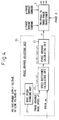
- Fig. 4 is a block diagram for explaining a first aspect of a phase advance adjusting unit.
- the phase advance adjusting unit 20 according to a first aspect includes a base speed changing unit 21 that changes a base speed (vf) at which a phase advance is started based on the measured voltage VI, and a speed difference calculating unit 22 that calculates a speed difference (vm-vf) between a motor actual speed (vm) and the base speed (vf) at which a phase advance is started.
- a phase advance calculating unit 23 multiplies a speed dependence coefficient KI of a phase advance to the speed difference (vm-vf) calculated by the speed difference calculating unit 22, thereby generating a phase advance (AI), and transmits the phase advance (AI) to a two-phase to three-phase transformer 6.
- a torque command (a q-phase current) may be taken into account in some cases.
- Fig. 5 is a block diagram for explaining a second aspect of a phase advance adjusting unit.
- the phase advance adjusting unit 20 according to a second aspect includes a phase advance maximum value changing unit 24 that changes a maximum value of a phase advance Phmax based on the measured voltage VI.
- the phase advance maximum value changing unit 24 multiplies a voltage dependence coefficient ⁇ of a phase advance maximum value to the difference (VI-VB) between the measured voltage VI and the reference voltage VB, thereby obtaining a product ( ⁇ (VI-VB)).
- the phase advance maximum value changing unit 24 adds this value ( ⁇ (VI-VB)) to a reference value Phmax0 of a maximum value of a phase advance, thereby generating the phase advance maximum value Phmax, and transmits the phase advance maximum value Phmax to the two-phase to three-phase transformer 6.
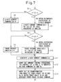
- Parameters of initial values to be used for the current control are read first. These parameters are stored into a recording medium in advance according to a specification of a motor, and these parameters can be read into a motor control device when necessary.
- the parameters include a reactive current base speed (vd0) that becomes a basis to determine a speed at which a reactive current is started to be passed, a reactive current maximum value (Idmax0) to determine a maximum reactive current, a phase advance base speed (vf0) at which a phase advance is started, and a phase advance maximum value (Phmax0).
- vd0 reactive current base speed
- Idmax0 reactive current maximum value
- vf0 phase advance base speed
- Phmax0 phase advance maximum value
- the voltage measuring unit 2 reads voltage information (VI) that is supplied to the power amplifier 7 (step S2), and a motor speed detector (not shown) reads speed information of the motor (step S3).
- a reactive current base speed at which a reactive current is started to be passed and a reactive current maximum value are obtained regarding the reactive current
- a phase advance base speed and a phase advance maximum value are obtained regarding the phase advance.
- the base speed changing unit 11 calculates a reactive current base speed (vd) at which a reactive current is started to be passed.
- VI denotes a power supply voltage (measured information)
- VB denotes a reference voltage
- vd0 denotes a reactive current base speed
- the coefficient ⁇ denotes a voltage dependence coefficient of the reactive current base speed.
- the reactive current maximum value changing unit 14 calculates a reactive current maximum value (Idmax) based on the following expression.
- Idmax Idmax 0 + ⁇ ⁇ ( VI - VB )
- VI denotes a power supply voltage (measured information)
- VB denotes a reference voltage
- Idmax0 denotes a reactive current maximum value
- the coefficient ⁇ denotes a voltage dependence coefficient of the reactive current maximum value.
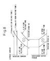
- the reactive current maximum value is set large (for example, E in Fig. 8).
- the reactive current maximum value is set small (for example, F in Fig. 8).
- phase advance is explained with reference to a diagram showing a phase advance and instantaneous torque characteristic in the phase advance control shown in Fig. 9.
- the base speed changing unit 21 calculates a phase advance base speed (vf) at which a phase advance is started.
- VI denotes a power supply voltage (measured information)
- VB denotes a reference voltage
- vf0 denotes a phase advance base speed at which a phase advance is started
- the coefficient ⁇ denotes a voltage dependence coefficient of the phase advance base speed.
- the phase advance base speed at which the phase advance is started is set to a low speed (for example, G in Fig. 9).
- the phase advance base speed at which the phase advance is started is set to a high speed (for example, H in Fig. 9).
- phase advance maximum value changing unit 24 calculates a phase advance maximum value (Phmax) based on the following expression.
- Phmax Phmax 0 + ⁇ ⁇ ( VI - VB )
- VI denotes a power supply voltage (measured information)
- VB denotes a reference voltage
- Phmax0 denotes a phase advance maximum value
- the coefficient ⁇ denotes a voltage dependence coefficient of the phase advance maximum value.
- the phase advance maximum value is set large (for example, K in Fig. 9).
- the phase advance maximum value is set small (for example, L in Fig. 9) (step S4).
- a reactive current command (a d-axis current command) is generated at step S5 to step S7.
- step S5 Until when the rotation speed (vm) of the rotor exceeds the speed (vd) at which a reactive current is started to be passed (step S5), the reactive current command (the d-axis current command) is kept at "0" (step S6).
- the reactive current command (the d-axis current command) is obtained.
- Kd denotes a speed dependence coefficient of a d-axis current
- vm denotes a rotation speed of a rotor
- vd denotes a speed at which a reactive current is started to be passed.
- the reactive current (Id) in the above expression shows a characteristic of a symbol C in Fig. 8 when the power supply voltage is a low voltage, and shows a characteristic of a symbol D in Fig. 8 when the power supply voltage is a high voltage.
- the reactive current maximum value (Idmax) is expressed by the symbol E in Fig. 8 when the power supply voltage is a low voltage, and is expressed by the symbol F in Fig. 8 when the power supply voltage is a high voltage, as explained above.
- the reactive current command (the d-axis current command) increases or decreases according to a size of the power supply voltage as shown in Fig. 8.
- the power supply voltage is high, an unnecessary reactive current can be suppressed, thereby increasing the continuous output torque in the high-speed area, as shown in the continuous output torque characteristic in Fig. 8 (step S7).
- phase advance (the phase advance angle) (AI) is kept at "0", and the phase is not advanced (step S9).
- the phase advance (the phase advance angle) (AI) is obtained.
- KI denotes a speed dependence coefficient of a phase advance
- vm denotes a rotation speed of a rotor
- vf denotes a speed at which a phase advance is started.
- phase advance (AI) in the above expression shows a characteristic of a symbol I in Fig. 9 when the power supply voltage is a low voltage, and shows a characteristic of a symbol J in Fig. 9 when the power supply voltage is a high voltage.
- phase advance maximum value (Phmax) is expressed by the symbol K in Fig. 9 when the power supply voltage is a low voltage, and is expressed by the symbol L in Fig. 9 when the power supply voltage is a high voltage, as explained above.
- phase advance increases or decreases according to a size of the power supply voltage as shown in Fig. 9.
- a maximum torque characteristic can be obtained at each voltage ranging from a low voltage to a high voltage (step S10).
- a d-phase current controller 4 controls a current (PI control) to generate a voltage command Vd
- a q-phase current controller 5 controls a current (PI control) to generate a voltage command Vq (step S12).
- a two-phase to three-phase transformer 6 generates a three-phase voltage command by DQ transformation of the generated voltage commands Vd and Vq using a phase angle ⁇ of the rotor and the phase advance (AI) obtained at steps S9 and S10, and transmits the obtained three-phase voltage command to the power amplifier 7 (step S13).
Landscapes
- Engineering & Computer Science (AREA)
- Power Engineering (AREA)
- Control Of Ac Motors In General (AREA)
- Control Of Motors That Do Not Use Commutators (AREA)
Priority Applications (1)
| Application Number | Priority Date | Filing Date | Title |
|---|---|---|---|
| EP12000580.6A EP2453573B1 (de) | 2004-06-30 | 2005-06-29 | Motorsteuervorrichtung |
Applications Claiming Priority (1)
| Application Number | Priority Date | Filing Date | Title |
|---|---|---|---|
| JP2004194222A JP4116595B2 (ja) | 2004-06-30 | 2004-06-30 | モータ制御装置 |
Related Child Applications (2)
| Application Number | Title | Priority Date | Filing Date |
|---|---|---|---|
| EP12000580.6A Division EP2453573B1 (de) | 2004-06-30 | 2005-06-29 | Motorsteuervorrichtung |
| EP12000580.6 Division-Into | 2012-01-30 |
Publications (3)
| Publication Number | Publication Date |
|---|---|
| EP1612929A2 true EP1612929A2 (de) | 2006-01-04 |
| EP1612929A3 EP1612929A3 (de) | 2011-03-16 |
| EP1612929B1 EP1612929B1 (de) | 2012-04-04 |
Family
ID=34993139
Family Applications (2)
| Application Number | Title | Priority Date | Filing Date |
|---|---|---|---|
| EP12000580.6A Expired - Lifetime EP2453573B1 (de) | 2004-06-30 | 2005-06-29 | Motorsteuervorrichtung |
| EP05014076A Ceased EP1612929B1 (de) | 2004-06-30 | 2005-06-29 | Motorreglungsvorrichtung |
Family Applications Before (1)
| Application Number | Title | Priority Date | Filing Date |
|---|---|---|---|
| EP12000580.6A Expired - Lifetime EP2453573B1 (de) | 2004-06-30 | 2005-06-29 | Motorsteuervorrichtung |
Country Status (4)
| Country | Link |
|---|---|
| US (1) | US7170256B2 (de) |
| EP (2) | EP2453573B1 (de) |
| JP (1) | JP4116595B2 (de) |
| CN (2) | CN100372225C (de) |
Cited By (1)
| Publication number | Priority date | Publication date | Assignee | Title |
|---|---|---|---|---|
| US9000694B2 (en) | 2012-03-23 | 2015-04-07 | Fanuc Corporation | Synchronous motor control apparatus |
Families Citing this family (20)
| Publication number | Priority date | Publication date | Assignee | Title |
|---|---|---|---|---|
| JP4116595B2 (ja) * | 2004-06-30 | 2008-07-09 | ファナック株式会社 | モータ制御装置 |
| US7292003B1 (en) * | 2006-08-10 | 2007-11-06 | Hamilton Sundstrand Corporation | Starter/generator with permanent magnet generator position indicator |
| JP4486654B2 (ja) * | 2007-01-29 | 2010-06-23 | 株式会社日立製作所 | 電動機制御システム、シリーズハイブリッド車両、電動機制御装置、及び電動機制御方法 |
| JP4654217B2 (ja) | 2007-04-25 | 2011-03-16 | 日立オートモティブシステムズ株式会社 | 永久磁石モータの弱め界磁制御装置及びそれを用いた電動パワーステアリング |
| US7915852B2 (en) * | 2008-02-22 | 2011-03-29 | Rockwell Automation Technologies, Inc. | Universal adaptive torque control for PM motors for field-weakening region operation |
| JP4582168B2 (ja) * | 2008-03-21 | 2010-11-17 | 株式会社デンソー | 回転機の制御装置、及び回転機の制御システム |
| JP5576039B2 (ja) | 2008-12-17 | 2014-08-20 | 株式会社日立産機システム | 同期電動機制御装置 |
| JP5140130B2 (ja) * | 2009-12-01 | 2013-02-06 | 日本電産テクノモータ株式会社 | モータ |
| US8432118B2 (en) * | 2011-05-02 | 2013-04-30 | Deere & Company | Inverter and a method for controlling an electric machine |
| JP5824918B2 (ja) * | 2011-07-04 | 2015-12-02 | 日産自動車株式会社 | インバータ制御装置及びインバータ制御方法 |
| JP5667153B2 (ja) * | 2012-12-03 | 2015-02-12 | ファナック株式会社 | 同期電動機の磁極位置検出装置 |
| FR3000630B1 (fr) * | 2012-12-27 | 2016-05-20 | Ge Energy Power Conversion Technology Ltd | Procede de commutation et dispositif de controle associe |
| JP5717808B2 (ja) | 2013-07-18 | 2015-05-13 | ファナック株式会社 | 同期電動機の電流制御装置 |
| JP2015109777A (ja) * | 2013-12-05 | 2015-06-11 | シンフォニアテクノロジー株式会社 | モータ制御装置 |
| JP5964391B2 (ja) * | 2014-10-31 | 2016-08-03 | ファナック株式会社 | dq三相座標の電流位相を制御するモータ制御装置 |
| US10288040B2 (en) * | 2015-09-11 | 2019-05-14 | General Electric Company | Current limit calculation for wind turbine control |
| JP7111471B2 (ja) * | 2018-01-24 | 2022-08-02 | マブチモーター株式会社 | 制御装置 |
| JP6730339B2 (ja) * | 2018-02-16 | 2020-07-29 | ファナック株式会社 | パラメータ決定支援装置及びプログラム |
| EP4277112A1 (de) * | 2022-05-09 | 2023-11-15 | Goodrich Control Systems | Einstellbare phasenvoreilung für eine pm-motorregelung |
| CN116667710A (zh) * | 2023-06-06 | 2023-08-29 | 西门子工厂自动化工程有限公司 | 电机控制方法、装置、电子设备和存储介质 |
Citations (1)
| Publication number | Priority date | Publication date | Assignee | Title |
|---|---|---|---|---|
| JP2003052199A (ja) | 2001-08-07 | 2003-02-21 | Fanuc Ltd | モータの制御装置 |
Family Cites Families (16)
| Publication number | Priority date | Publication date | Assignee | Title |
|---|---|---|---|---|
| US4455520A (en) * | 1981-05-29 | 1984-06-19 | Compumotor Corporation | Method and means for stable operation of a synchronous motor |
| US4570214A (en) * | 1984-03-29 | 1986-02-11 | Tokyo Shibaura Denki Kabushiki Kaisha | Reactive power control cycloconverter |
| US4651068A (en) * | 1984-10-01 | 1987-03-17 | Electro-Craft Corporation | Brushless motor control circuitry with optimum current vector control |
| DE4100864A1 (de) * | 1991-01-14 | 1992-07-16 | Schaltbau Gmbh | Verfahren zum ansteuern eines elektrischen synchronmotors |
| WO1994007301A1 (de) * | 1992-09-24 | 1994-03-31 | Siemens Aktiengesellschaft | Verfahren und vorrichtung zur regelung eines umrichtergespeisten permanenterregten synchronmotors |
| DE69416747T2 (de) * | 1993-08-10 | 1999-07-29 | Toyota Jidosha K.K., Toyota, Aichi | Vorrichtung zum Antrieb und zur Steuerung von Synchronmotoren, die Permanentmagnete als Erregungssystem benützen |
| JPH08182398A (ja) * | 1994-12-27 | 1996-07-12 | Fuji Electric Co Ltd | 永久磁石形同期電動機の駆動装置 |
| JPH10177370A (ja) * | 1996-10-16 | 1998-06-30 | Oki Lsi Technol Kansai:Kk | 多階調出力回路及び液晶表示装置 |
| JP2000354392A (ja) * | 1999-06-09 | 2000-12-19 | Denso Corp | ブラシレスモータ |
| JP3515460B2 (ja) * | 1999-12-24 | 2004-04-05 | 本田技研工業株式会社 | 交流モータの制御装置 |
| JP4465129B2 (ja) * | 2000-07-14 | 2010-05-19 | パナソニック株式会社 | ブラシレスモータの駆動装置と駆動方法 |
| JP3700576B2 (ja) * | 2000-11-24 | 2005-09-28 | 松下電器産業株式会社 | モータ制御装置 |
| JP3701207B2 (ja) * | 2001-02-27 | 2005-09-28 | 株式会社日立製作所 | モータ制御装置及びそれを用いた電動車両 |
| JP3726713B2 (ja) * | 2001-06-14 | 2005-12-14 | 日産自動車株式会社 | 電動機の制御装置 |
| JP2003169500A (ja) * | 2001-11-30 | 2003-06-13 | Mitsubishi Electric Corp | 同期機の励磁制御装置 |
| JP4116595B2 (ja) * | 2004-06-30 | 2008-07-09 | ファナック株式会社 | モータ制御装置 |
-
2004
- 2004-06-30 JP JP2004194222A patent/JP4116595B2/ja not_active Expired - Fee Related
-
2005
- 2005-06-28 US US11/167,254 patent/US7170256B2/en not_active Expired - Lifetime
- 2005-06-29 EP EP12000580.6A patent/EP2453573B1/de not_active Expired - Lifetime
- 2005-06-29 EP EP05014076A patent/EP1612929B1/de not_active Ceased
- 2005-06-30 CN CNB2005100805923A patent/CN100372225C/zh not_active Expired - Fee Related
- 2005-06-30 CN CN2007101533183A patent/CN101154906B/zh not_active Expired - Fee Related
Patent Citations (1)
| Publication number | Priority date | Publication date | Assignee | Title |
|---|---|---|---|---|
| JP2003052199A (ja) | 2001-08-07 | 2003-02-21 | Fanuc Ltd | モータの制御装置 |
Cited By (2)
| Publication number | Priority date | Publication date | Assignee | Title |
|---|---|---|---|---|
| US9000694B2 (en) | 2012-03-23 | 2015-04-07 | Fanuc Corporation | Synchronous motor control apparatus |
| US9136789B2 (en) | 2012-03-23 | 2015-09-15 | Fanuc Corporation | Synchronous motor control apparatus |
Also Published As
| Publication number | Publication date |
|---|---|
| JP2006020397A (ja) | 2006-01-19 |
| US20060012327A1 (en) | 2006-01-19 |
| CN101154906A (zh) | 2008-04-02 |
| EP1612929B1 (de) | 2012-04-04 |
| CN101154906B (zh) | 2012-04-25 |
| EP1612929A3 (de) | 2011-03-16 |
| EP2453573B1 (de) | 2017-09-20 |
| CN100372225C (zh) | 2008-02-27 |
| JP4116595B2 (ja) | 2008-07-09 |
| US7170256B2 (en) | 2007-01-30 |
| CN1716752A (zh) | 2006-01-04 |
| EP2453573A1 (de) | 2012-05-16 |
Similar Documents
| Publication | Publication Date | Title |
|---|---|---|
| EP1612929B1 (de) | Motorreglungsvorrichtung | |
| EP1378990B1 (de) | Steuergerät für einen Elektromotor | |
| CN100449934C (zh) | 定子电流目标值和扭矩目标值的受控应用方法 | |
| US6570358B2 (en) | Control apparatus for alternating-current motor | |
| US6462492B1 (en) | Position-sensorless controlling method of synchronous motor | |
| US9614473B1 (en) | Flux weakening AC motor control by voltage vector angle deflection | |
| EP1662650B1 (de) | Verfahren und Vorrichtung zur Steuerung eines Synchronmotors | |
| US7443127B2 (en) | Apparatus and method for motor control using table | |
| US9602035B2 (en) | Driving apparatus for electric motor | |
| US20060038530A1 (en) | System and method for optimizing motor performance by varying flux | |
| US6707270B2 (en) | System and method for induction motor control | |
| JP6199776B2 (ja) | 電動機の駆動装置 | |
| EP2618480A2 (de) | Motorsteuerungsvorrichtung und Klimaanlage | |
| EP4207586A1 (de) | Motorsteuerungsverfahren und motorsteuerungsvorrichtung | |
| US7026785B1 (en) | Motor controller | |
| EP3098961B1 (de) | System zur steuerung eines elektrischen induktionsmotor | |
| JP3944659B2 (ja) | 誘導電動機の制御装置 | |
| US20250158544A1 (en) | Multi-motor converter | |
| JPH07274600A (ja) | 誘導電動機の加減速制御方法及び制御装置 | |
| CN115085622B (zh) | 永磁同步电机标定方法、最大转矩电流比标定方法及设备 | |
| KR100313251B1 (ko) | 모터의구동제어장치 | |
| JPH11113300A (ja) | 誘導電動機制御装置 | |
| JP2000037099A (ja) | 交流電動機の可変速制御装置 | |
| JP2002199796A (ja) | 誘導電動機の制御装置及び方法 |
Legal Events
| Date | Code | Title | Description |
|---|---|---|---|
| PUAI | Public reference made under article 153(3) epc to a published international application that has entered the european phase |
Free format text: ORIGINAL CODE: 0009012 |
|
| AK | Designated contracting states |
Kind code of ref document: A2 Designated state(s): AT BE BG CH CY CZ DE DK EE ES FI FR GB GR HU IE IS IT LI LT LU MC NL PL PT RO SE SI SK TR |
|
| AX | Request for extension of the european patent |
Extension state: AL BA HR LV MK YU |
|
| 17P | Request for examination filed |
Effective date: 20100303 |
|
| PUAL | Search report despatched |
Free format text: ORIGINAL CODE: 0009013 |
|
| RAP1 | Party data changed (applicant data changed or rights of an application transferred) |
Owner name: FANUC CORPORATION |
|
| AK | Designated contracting states |
Kind code of ref document: A3 Designated state(s): AT BE BG CH CY CZ DE DK EE ES FI FR GB GR HU IE IS IT LI LT LU MC NL PL PT RO SE SI SK TR |
|
| AX | Request for extension of the european patent |
Extension state: AL BA HR LV MK YU |
|
| GRAP | Despatch of communication of intention to grant a patent |
Free format text: ORIGINAL CODE: EPIDOSNIGR1 |
|
| RIN1 | Information on inventor provided before grant (corrected) |
Inventor name: OKITA, TADASHI Inventor name: IWASHITA, YASUSUKE Inventor name: KOUGAMI, HIROSHI |
|
| AKX | Designation fees paid |
Designated state(s): DE |
|
| GRAS | Grant fee paid |
Free format text: ORIGINAL CODE: EPIDOSNIGR3 |
|
| GRAA | (expected) grant |
Free format text: ORIGINAL CODE: 0009210 |
|
| AK | Designated contracting states |
Kind code of ref document: B1 Designated state(s): DE |
|
| REG | Reference to a national code |
Ref country code: DE Ref legal event code: R096 Ref document number: 602005033464 Country of ref document: DE Effective date: 20120531 |
|
| PLBE | No opposition filed within time limit |
Free format text: ORIGINAL CODE: 0009261 |
|
| STAA | Information on the status of an ep patent application or granted ep patent |
Free format text: STATUS: NO OPPOSITION FILED WITHIN TIME LIMIT |
|
| 26N | No opposition filed |
Effective date: 20130107 |
|
| REG | Reference to a national code |
Ref country code: DE Ref legal event code: R097 Ref document number: 602005033464 Country of ref document: DE Effective date: 20130107 |
|
| PGFP | Annual fee paid to national office [announced via postgrant information from national office to epo] |
Ref country code: DE Payment date: 20230502 Year of fee payment: 19 |
|
| REG | Reference to a national code |
Ref country code: DE Ref legal event code: R119 Ref document number: 602005033464 Country of ref document: DE |
|
| PG25 | Lapsed in a contracting state [announced via postgrant information from national office to epo] |
Ref country code: DE Free format text: LAPSE BECAUSE OF NON-PAYMENT OF DUE FEES Effective date: 20250101 |