EP1613070A2 - Flüssigkristallanzeigegerät - Google Patents
Flüssigkristallanzeigegerät Download PDFInfo
- Publication number
- EP1613070A2 EP1613070A2 EP05253953A EP05253953A EP1613070A2 EP 1613070 A2 EP1613070 A2 EP 1613070A2 EP 05253953 A EP05253953 A EP 05253953A EP 05253953 A EP05253953 A EP 05253953A EP 1613070 A2 EP1613070 A2 EP 1613070A2
- Authority
- EP
- European Patent Office
- Prior art keywords
- recording
- liquid crystal
- lcd
- casing
- playing device
- Prior art date
- Legal status (The legal status is an assumption and is not a legal conclusion. Google has not performed a legal analysis and makes no representation as to the accuracy of the status listed.)
- Withdrawn
Links
Images




Classifications
-
- H—ELECTRICITY
- H04—ELECTRIC COMMUNICATION TECHNIQUE
- H04N—PICTORIAL COMMUNICATION, e.g. TELEVISION
- H04N5/00—Details of television systems
- H04N5/64—Constructional details of receivers, e.g. cabinets or dust covers
-
- H—ELECTRICITY
- H04—ELECTRIC COMMUNICATION TECHNIQUE
- H04N—PICTORIAL COMMUNICATION, e.g. TELEVISION
- H04N5/00—Details of television systems
- H04N5/76—Television signal recording
- H04N5/765—Interface circuits between an apparatus for recording and another apparatus
- H04N5/775—Interface circuits between an apparatus for recording and another apparatus between a recording apparatus and a television receiver
Definitions
- the present invention relates to a liquid crystal display device for displaying images, such as a liquid crystal television receiver, and more specifically, to a liquid crystal display device capable of mounting a recording/playing device for recording and playing data on a recording medium such as an optical disk like a DVD (digital versatile disk).
- a liquid crystal display device capable of mounting a recording/playing device for recording and playing data on a recording medium such as an optical disk like a DVD (digital versatile disk).
- a single electronic device is equipped with both the function of a television receiver and the function of a recording/playing device of an optical disk such as DVD, allowing the user to view both the data on a DVD and a television broadcast program.
- an optical disk recording/playing device on an existing television receiver at a later timing, it may be possible to mount the device if there is enough space inside the casing of the electronic device to mount the recording/playing device, but in practice, it was difficult to mount and lay out manipulation buttons and circuit boards for controlling the recording/playing device accompanying the mounting of the recording/playing device.
- the present invention aims at solving the above-mentioned problems of the prior art, by providing at low cost a liquid crystal display device capable of providing recording/playing device manipulation buttons for manipulating the recording/playing device on the display device by changing only a portion of the design of a mounting cover attached to the casing of the liquid crystal display device upon mounting a recording/playing device for a DVD and the like inside the casing of the liquid crystal display device.
- the first aspect of the present invention relates to a liquid crystal display device comprising a mounting cover for fixing an LCD device inside a casing of the liquid crystal display device, and an LCD manipulation button for manipulating the LCD device provided on the mounting cover, wherein upon mounting inside the casing a recording/playing device for recording and playing data on an optical disk, the mounting cover is used commonly with a position for providing a recording/playing device manipulation button for manipulating the recording/playing device being different from a position for providing the LCD manipulation button.
- the mounting cover upon mounting a recording/playing device inside the casing of a liquid crystal display device, can be used commonly except that the position for placing the recording/playing device manipulation button is different from the position for placing the LCD manipulation button.
- the second aspect of the present invention relates to the liquid crystal display device according to the first aspect, wherein the LCD manipulation button is provided at an upper face of the casing at substantially a longitudinal center thereof.
- the operator of the liquid crystal display device can manipulate the LCD device easily from any direction, since the LCD manipulation button is placed at the upper face of the casing at substantially the longitudinal center of the casing.
- the third aspect of the present invention relates to the liquid crystal display device according to the second aspect, wherein upon mounting the recording/playing device inside the casing, the LCD manipulation button and the recording/playing device manipulation button are provided at the upper face of the casing at substantially the longitudinal center thereof.
- the LCD manipulation button and the recording/playing device manipulation button are provided at the upper face of the casing at substantially the longitudinal center thereof, so that the manipulation of the LCD device and the recording/playing device can be performed easily from any direction.
- a liquid crystal display device comprising a mounting cover for fixing an LCD device inside a casing of the liquid crystal display device, and an LCD manipulation button for manipulating the LCD device provided on the mounting cover, wherein upon mounting inside the casing a recording/playing device for recording and playing data on an optical disk, the mounting cover is used commonly with a position for providing a recording/playing device manipulation button for manipulating the recording/playing device being different from a position for providing the LCD manipulation button, the mounting cover can be used commonly to thereby reduce the number of components constituting the liquid crystal display device.
- the present invention enables to provide a liquid crystal display device at low cost.
- the present liquid crystal display device has superior operability.
- the present liquid crystal display device related to the liquid crystal display device of the second aspect wherein upon mounting the recording/playing device inside the casing, the LCD manipulation button and the recording/playing device manipulation button are provided at the upper face of the casing at substantially the longitudinal center thereof, the liquid crystal display device having the recording/playing device mounted thereto can be manipulated easily from any direction using the recording/playing device manipulation button and the LCD manipulation button. Therefore, the present liquid crystal display device has superior operability.
- FIGS. 1 through 9 The technical scope of the present invention is not restricted to the language used in the embodiments, and is extended to the range in which a person skilled in the art could easily substitute based on the present disclosure.
- FIG. 1 is a front view of a liquid crystal display device capable of receiving and displaying a television broadcast program and the like
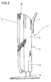
- FIG. 2 is a left side view thereof
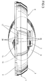
- FIG. 3 is a plan view thereof.
- the liquid crystal display device according to the present embodiment is a liquid crystal television receiver 1.
- the liquid crystal television receiver 1 is composed of a casing 5 including a front cabinet 2, a back cabinet 3 and a back cover 4 that can be separated. In a center front area of the front cabinet 2 is disposed a display unit 6 for displaying images.
- a handle 7 is screwed on the upper portion of the back cabinet 3 for moving the liquid crystal television receiver 1.
- a stand 8 for mounting the liquid crystal television receiver 1 is screwed on the bottom surface of the back cabinet 3 at the longitudinal center thereof.
- manipulation buttons 10 of the liquid crystal display (LCD) for allowing various manipulations of the display unit 6 of the LCD device 13, as illustrated in FIG. 3.
- LCD manipulation buttons 10 are provided so as to protrude upward via through holes 11 provided on the upper portion of the back cabinet 3.
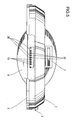
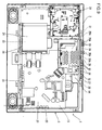
- FIG. 4 is a drawing showing the state in which the back cabinet 3 and back cover 4 are removed to show the interior of the casing 5 of the liquid crystal television receiver 1, and inside the casing 5 is an LCD device 13 equipped with a display unit 6 disposed in the front cabinet 2, the device 13 being fixed to the front cabinet 2 by a mounting cover 14 via a screw or the like.
- a television board 20 and a digital board 23 for controlling the LCD device 13 or the like there are provided a digital board shield 24 covering the digital board 23, and jack mounting plates 25, 25 and 25 for mounting multiple jacks.
- a digital board shield 24 covering the digital board 23, and jack mounting plates 25, 25 and 25 for mounting multiple jacks.
- jack mounting plates 25, 25 and 25 and 25 for mounting multiple jacks.
- through holes 11 on the back cabinet 3 which are positioned to correspond to the LCD manipulation buttons 10, and through the through holes 11, button covers 26 provided to the LCD manipulation buttons 10 are exposed to the exterior.
- the LCD manipulation buttons 10 are integrally mounted to the television control board 27, as shown in FIGS. 3 through 5, and screwed onto mounting holes 28 provided to the mounting cover 14 through the television control board 27.
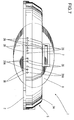
- FIG. 9 shows a state in which a recording/playing device 30 is mounted to the casing 5 of the liquid crystal television receiver 1.
- the arrangement of the liquid crystal television receiver 1 according to this arrangement is substantially the same as that mentioned above, so the same components are denoted with the same reference numbers and detailed descriptions thereof are omitted.
- a recording/playing device 30 When providing a recording/playing device 30 to the casing 5 of the liquid crystal television receiver 1, at least a recording/playing device 30, a recording/playing device board 31 for controlling the recording/playing device 30 and a board shield 32 covering the recording/playing device board 31 are additionally mounted to the interior of the casing 5, as shown in FIG. 9. Further, holes 28A, 28A, 28A and 28A are provided to the mounting cover 14 instead of the mounting holes 28 and 28, as shown in FIG. 9.
- the LCD manipulation buttons 10 and recording/playing device manipulation buttons 33 for manipulating the recording/playing device 30 are secured to holes 28A, 28A, 28A and 28A via screw engagement and the like.
- the LCD manipulation buttons 10 and the recording/playing device buttons 32 are provided integrally on the television control board 27 and the recording/playing device control board 34, respectively, and the buttons are screw engaged to the mounting holes 28A provided on the mounting cover 14 through the television control board 27 and the recording/playing device control board 34.
- the LCD manipulation buttons 10 and the recording/playing device buttons 33 are covered by button covers 26 provided on the LCD manipulation button 10 and button covers 26A provided on the recording/playing device buttons 33, wherein these button covers 26 and 26A are exposed through the openings 35 to the exterior.
- a recording/playing device 30 is mounted inside the casing 5 of the liquid crystal television receiver 1
- a corresponding recording/playing device board 31 is fixed to the interior of the casing 5, and a mounting cover 14 with substantially the same shape but having holes 28A instead of mounting holes 28 is used commonly.
- a rear cabinet 3A having openings 35 corresponding to the location of LCD manipulation buttons 10 and recording/playing device buttons 32 is used as the rear cabinet 3A.
- the rear cabinet 3A when replacing the back cabinet 3 corresponding only to the LCD manipulation button 10 with the rear cabinet 3A corresponding both to the LCD manipulation button 10 and the recording/playing device buttons 32, the rear cabinet 3A can be manufactured at low cost since the rear cabinet 3A can be formed easily using a nesting or the like in a mold (not shown) used to form the back cabinet 3. Furthermore, when mounting a recording/playing device 30 in the casing 5 of the liquid crystal television receiver 1, the rear cabinet 3A is provided with an opening 12 for inserting an optical disk to the recording/playing device 30, as shown in FIG. 6.
- the liquid crystal television receiver 1 as the liquid crystal display device according to the present embodiment is provided with a mounting cover 14 for fixing an LCD device 13 inside the casing 5 of the liquid crystal television receiver 1, the mounting cover 14 equipped with LCD manipulation buttons 10 for controlling the LCD device 13, wherein when mounting a recording/playing device 30 for recording and playing data on an optical disk to the interior of the casing 5, recording/playing device manipulation buttons 33 are also provided on the mounting cover 14.
- the mounting cover 14 is used commonly except that the mounting positions of the recording/playing device manipulation buttons 33 for controlling the recording/playing device 30 are different from the mounting positions of the LCD manipulation buttons 10, so that the number of components constituting the liquid crystal television receiver 1 is reduced and the cost for manufacturing the television receiver 1 can thereby be cut down. Since the LCD manipulation buttons 10 are provided substantially at the longitudinal center of the upper face of the casing 5, the operator of the liquid crystal television receiver 1 can manipulate the LCD device 13 easily from any direction through the LCD manipulation buttons 10, since the LCD manipulation buttons 10 are provided at the upper face of the casing 14 and at substantially the longitudinal center thereof. Thus, the television receiver 1 has superior operability.
- both the LCD manipulation buttons 10 and recording/playing device manipulation buttons 33 are provided at the upper face of the casing 14 at substantially the longitudinal center thereof, so in addition to the LCD device 13, the recording/playing device 30 mounted on the liquid crystal television receiver 1 can be manipulated easily from any direction since the LCD manipulation buttons 10 for manipulating the television to show television broadcasts and the recording/playing device manipulation buttons 33 for manipulating the recording/playing device 30 are provided at the upper face of the casing 14 at substantially the longitudinal center thereof. Therefore, the present television receiver 1 has superior operability.
- the term "recording/playing” used in the above description refers both to recording or playing (reproducing) data and recording and playing data.
- One effect of the present embodiment is that since the LCD manipulation buttons 10 of FIG. 3 or the LCD manipulation buttons 10 and the recording/playing device manipulation buttons 33 of FIG. 7 are provided on the upper area of the stand placed on a floor or the like, so that even if the LCD manipulation buttons 10 or the recording/playing device manipulation buttons 33 are pressed from above with relatively strong force, the liquid crystal television receiver 1 mounted on the stand will not loose balance and tilt over, but can maintain a stable position on the floor.
Landscapes
- Engineering & Computer Science (AREA)
- Multimedia (AREA)
- Signal Processing (AREA)
- Devices For Indicating Variable Information By Combining Individual Elements (AREA)
Applications Claiming Priority (1)
| Application Number | Priority Date | Filing Date | Title |
|---|---|---|---|
| JP2004193520A JP2006019865A (ja) | 2004-06-30 | 2004-06-30 | 液晶画像表示装置 |
Publications (2)
| Publication Number | Publication Date |
|---|---|
| EP1613070A2 true EP1613070A2 (de) | 2006-01-04 |
| EP1613070A3 EP1613070A3 (de) | 2007-10-17 |
Family
ID=35169674
Family Applications (1)
| Application Number | Title | Priority Date | Filing Date |
|---|---|---|---|
| EP05253953A Withdrawn EP1613070A3 (de) | 2004-06-30 | 2005-06-24 | Flüssigkristallanzeigegerät |
Country Status (3)
| Country | Link |
|---|---|
| US (1) | US20060002063A1 (de) |
| EP (1) | EP1613070A3 (de) |
| JP (1) | JP2006019865A (de) |
Cited By (3)
| Publication number | Priority date | Publication date | Assignee | Title |
|---|---|---|---|---|
| EP1577894A3 (de) * | 2004-03-19 | 2008-01-09 | ORION ELECTRIC CO., Ltd. | Flüssigkristall - Anzeigevorrichtung mit integrierter Plattenvorrichtung |
| EP2076107A3 (de) * | 2007-12-28 | 2009-10-07 | Orion Electric Co., Ltd | Anzeigevorrichtung |
| EP1990815A3 (de) * | 2007-05-08 | 2010-04-07 | Funai Electric Co., Ltd. | Anzeigevorrichtung |
Families Citing this family (7)
| Publication number | Priority date | Publication date | Assignee | Title |
|---|---|---|---|---|
| TWM287953U (en) * | 2005-10-05 | 2006-02-21 | Proview Electronics Co Ltd | Modular liquid crystal display monitor |
| CN100443975C (zh) * | 2005-12-21 | 2008-12-17 | 群康科技(深圳)有限公司 | 液晶显示装置 |
| JP4122460B2 (ja) * | 2006-05-24 | 2008-07-23 | 船井電機株式会社 | ディスク装置一体型液晶表示装置 |
| JP4171927B2 (ja) * | 2006-09-19 | 2008-10-29 | 船井電機株式会社 | 液晶パネル、プラズマ表示パネルおよびワイド型液晶テレビジョン |
| ITMO20070272A1 (it) * | 2007-08-29 | 2009-02-28 | Sacmi | Apparato per trasferire oggetti |
| JP2009181038A (ja) * | 2008-01-31 | 2009-08-13 | Sharp Corp | 表示装置 |
| US20100125878A1 (en) * | 2008-11-19 | 2010-05-20 | Sony Corporation | Embedded wireless antenna for network tv |
Family Cites Families (11)
| Publication number | Priority date | Publication date | Assignee | Title |
|---|---|---|---|---|
| FR1194974A (fr) * | 1957-05-31 | 1959-11-13 | Telefunken Gmbh | Dispositif de commande pour récepteurs de télévision |
| US5887837A (en) * | 1996-09-30 | 1999-03-30 | Johns; H. Douglas | Pivotal computer stand |
| AU5069698A (en) * | 1996-11-12 | 1998-06-03 | Carlos Landetta Chombo | Electronic book |
| JPH10222244A (ja) * | 1997-02-07 | 1998-08-21 | Hitachi Ltd | デスクトップ型コンピュータ |
| WO2000041089A1 (en) * | 1999-01-06 | 2000-07-13 | Harrison Robert G | Appliances with multiple modes of operation |
| JP3075808U (ja) * | 2000-08-23 | 2001-03-06 | 船井電機株式会社 | Dvd装置内蔵型テレビジョン |
| US20020149905A1 (en) * | 2001-04-11 | 2002-10-17 | Jackson, Louiss R. | Flat hanging computer |
| US6621691B2 (en) * | 2001-07-10 | 2003-09-16 | Dell Products L.P. | Portable computer with top mounted optical drive |
| TWI247981B (en) * | 2001-11-15 | 2006-01-21 | Wistron Corp | Computer with a detachable liquid crystal display |
| US6822851B2 (en) * | 2001-12-26 | 2004-11-23 | Sony Corporation | Electronic device |
| US7079293B2 (en) * | 2003-04-08 | 2006-07-18 | Tr Marketing, Inc. | Digital album and methods of use |
-
2004
- 2004-06-30 JP JP2004193520A patent/JP2006019865A/ja not_active Withdrawn
-
2005
- 2005-06-24 EP EP05253953A patent/EP1613070A3/de not_active Withdrawn
- 2005-06-28 US US11/167,237 patent/US20060002063A1/en not_active Abandoned
Cited By (4)
| Publication number | Priority date | Publication date | Assignee | Title |
|---|---|---|---|---|
| EP1577894A3 (de) * | 2004-03-19 | 2008-01-09 | ORION ELECTRIC CO., Ltd. | Flüssigkristall - Anzeigevorrichtung mit integrierter Plattenvorrichtung |
| EP1990815A3 (de) * | 2007-05-08 | 2010-04-07 | Funai Electric Co., Ltd. | Anzeigevorrichtung |
| US8144268B2 (en) | 2007-05-08 | 2012-03-27 | Funai Electric Co., Ltd. | Display device |
| EP2076107A3 (de) * | 2007-12-28 | 2009-10-07 | Orion Electric Co., Ltd | Anzeigevorrichtung |
Also Published As
| Publication number | Publication date |
|---|---|
| US20060002063A1 (en) | 2006-01-05 |
| EP1613070A3 (de) | 2007-10-17 |
| JP2006019865A (ja) | 2006-01-19 |
Similar Documents
| Publication | Publication Date | Title |
|---|---|---|
| EP1796384B1 (de) | Bildanzeigevorrichtung | |
| US7948752B2 (en) | Electronic device | |
| US20060002063A1 (en) | Liquid crystal display device | |
| JP2008301117A (ja) | 画像表示装置用スタンド | |
| US7738239B2 (en) | Electronic apparatus | |
| CN101888887B (zh) | 游戏机的界面单元及游戏机 | |
| JP5070451B2 (ja) | 遊技機 | |
| US8400572B2 (en) | Interchangeable switch assembly for media device | |
| US20070133158A1 (en) | Display device | |
| JP2005070969A (ja) | 電子機器および電子機器に用いる操作ユニット | |
| JP2006100671A (ja) | 電子機器 | |
| US20040257490A1 (en) | LCD device having a combined bezel and front housing | |
| JP4952431B2 (ja) | スピーカー装置 | |
| JP2011181127A (ja) | 映像表示装置 | |
| US6133527A (en) | Apparatus for securing cable and electric device comprising the same | |
| US8228447B2 (en) | Image display module | |
| JP5440902B2 (ja) | 画像形成装置 | |
| JPH11184559A (ja) | 携帯形情報機器 | |
| JP2006050602A (ja) | マルチメディアプレーヤ | |
| JP2009181038A (ja) | 表示装置 | |
| JP3162320U (ja) | 表示装置及び表示システム | |
| US20070097082A1 (en) | Electronic device including digital tuner unit | |
| JP3204877B2 (ja) | 資料提示装置 | |
| JP2012129883A (ja) | 電子機器 | |
| JP4116375B2 (ja) | 薄型表示装置 |
Legal Events
| Date | Code | Title | Description |
|---|---|---|---|
| PUAI | Public reference made under article 153(3) epc to a published international application that has entered the european phase |
Free format text: ORIGINAL CODE: 0009012 |
|
| AK | Designated contracting states |
Kind code of ref document: A2 Designated state(s): AT BE BG CH CY CZ DE DK EE ES FI FR GB GR HU IE IS IT LI LT LU MC NL PL PT RO SE SI SK TR |
|
| AX | Request for extension of the european patent |
Extension state: AL BA HR LV MK YU |
|
| PUAL | Search report despatched |
Free format text: ORIGINAL CODE: 0009013 |
|
| AK | Designated contracting states |
Kind code of ref document: A3 Designated state(s): AT BE BG CH CY CZ DE DK EE ES FI FR GB GR HU IE IS IT LI LT LU MC NL PL PT RO SE SI SK TR |
|
| AX | Request for extension of the european patent |
Extension state: AL BA HR LV MK YU |
|
| RIC1 | Information provided on ipc code assigned before grant |
Ipc: H04N 5/64 20060101ALI20070907BHEP Ipc: H04N 5/775 20060101AFI20070907BHEP |
|
| AKX | Designation fees paid | ||
| REG | Reference to a national code |
Ref country code: DE Ref legal event code: 8566 |
|
| STAA | Information on the status of an ep patent application or granted ep patent |
Free format text: STATUS: THE APPLICATION IS DEEMED TO BE WITHDRAWN |
|
| 18D | Application deemed to be withdrawn |
Effective date: 20080418 |