EP1614948B1 - Ventil - Google Patents
Ventil Download PDFInfo
- Publication number
- EP1614948B1 EP1614948B1 EP05014519A EP05014519A EP1614948B1 EP 1614948 B1 EP1614948 B1 EP 1614948B1 EP 05014519 A EP05014519 A EP 05014519A EP 05014519 A EP05014519 A EP 05014519A EP 1614948 B1 EP1614948 B1 EP 1614948B1
- Authority
- EP
- European Patent Office
- Prior art keywords
- valve
- valve according
- arch
- valve body
- section
- Prior art date
- Legal status (The legal status is an assumption and is not a legal conclusion. Google has not performed a legal analysis and makes no representation as to the accuracy of the status listed.)
- Expired - Lifetime
Links
Images



Classifications
-
- F—MECHANICAL ENGINEERING; LIGHTING; HEATING; WEAPONS; BLASTING
- F16—ENGINEERING ELEMENTS AND UNITS; GENERAL MEASURES FOR PRODUCING AND MAINTAINING EFFECTIVE FUNCTIONING OF MACHINES OR INSTALLATIONS; THERMAL INSULATION IN GENERAL
- F16K—VALVES; TAPS; COCKS; ACTUATING-FLOATS; DEVICES FOR VENTING OR AERATING
- F16K1/00—Lift valves or globe valves, i.e. cut-off apparatus with closure members having at least a component of their opening and closing motion perpendicular to the closing faces
- F16K1/32—Details
- F16K1/34—Cutting-off parts, e.g. valve members, seats
- F16K1/36—Valve members
- F16K1/40—Valve members of helical shape
-
- F—MECHANICAL ENGINEERING; LIGHTING; HEATING; WEAPONS; BLASTING
- F16—ENGINEERING ELEMENTS AND UNITS; GENERAL MEASURES FOR PRODUCING AND MAINTAINING EFFECTIVE FUNCTIONING OF MACHINES OR INSTALLATIONS; THERMAL INSULATION IN GENERAL
- F16K—VALVES; TAPS; COCKS; ACTUATING-FLOATS; DEVICES FOR VENTING OR AERATING
- F16K47/00—Means in valves for absorbing fluid energy
- F16K47/08—Means in valves for absorbing fluid energy for decreasing pressure or noise level and having a throttling member separate from the closure member, e.g. screens, slots, labyrinths
- F16K47/12—Means in valves for absorbing fluid energy for decreasing pressure or noise level and having a throttling member separate from the closure member, e.g. screens, slots, labyrinths the throttling channel being of helical form
Definitions
- the invention relates to a valve which is movable from an open position to a closed position and back, with a valve body whose base is adapted to the inner contour of a conduit and having a spirally formed vault.
- a valve of the type mentioned is, for example, from GB 15 970 A AO 1914 known.
- the conical vault can be brought from an open to a closed position by means of a release rod, which can be actuated from the outside.
- a similar valve is in the DE 500 753 C shown here, inter alia, with a spherical segment-like vault of the base body.
- a rod-like triggering element is provided, which, similar to the GB 15 970 A , AO 1914, is operable from the outside.
- the cross section of the spiral strand of the valve body is selected so that superimposed passages of the spiral strand engage in the closed position.
- the valve according to the invention operates effectively in that its cross-section is opened or closed uniformly. Due to the spiral-like cut the passage opening is maximum, so that there is a low flow resistance. Due to the supporting effect of the spiral superimposed segments, large diameters of lines can be bridged. This working principle is comparable to a vaulted cellar.
- the starting behavior of the valve can be adjusted via the cone angle or the pitch of the spiral.
- the design of the profile of the spiral strand of the valve body, the flow resistance and thus the performance of the valve can be adjusted. By selecting the profile, the supporting effect of the superimposed passages of the spiral strand can be improved.
- cross section of the spiral strand means the cutting plane perpendicular to the axis of the rolled spiral strand, as illustrated in connection with FIG.
- the vault may be a conical vault, but it is also advantageous if the vault is a spherical segment-like vault.
- a trigger element is provided, which is preferably attached to the zenith of the vault. This trigger element is intended to bring the valve in the open position.
- the trigger element can be actuated by a spring attached to it. With a separate spring on the trigger element, the valve can be used as a gas flow monitor.
- the spring is arranged in the axis of symmetry of the concavity of the arch.
- valve body itself serves as a spring which controls the triggering directly.
- valve according to the invention In order to use the valve according to the invention as a guard, in particular gas monitor, it must be the appropriate operating conditions, such as pressure, flow rate, etc., adapted.
- the spirally formed vault is made of metal or plastic, for example polypropylene, polyethylene, polyamide or the like. It is possible to add to the plastic fillers, such as glass fiber, carbon black or the like, so that the desired spring properties of the valve body are obtained.
- the cross section of the spiral strand is constant over at least part of its length. But it may also be required that the valve over its axial length has an approximately uniform bending stiffness. In this case it can be provided that the cross section of the spiral strand decreases from the base to the zenith of the arch. The thickness of the spiral strand therefore becomes smaller as the circumference of the valve body decreases.
- the flow-through opening formed in the spiral-shaped vault in the open position remains partially closed in the open position or can be closed. This can be achieved, for example, by already cutting only a portion of the valve body during manufacture in a spiral manner. But it can also be provided to subsequently apply a cover.
- Such a cover may rest more or less closely on the valve body and thus provide an increase in the back pressure.
- the flow resistance can be adjusted, which has an effect on the closing properties of the valve.
- a manufacturing simplification results when the cover is formed asymmetrically with respect to the longitudinal axis of the valve body.
- the cover element possible manufacturing tolerances can be compensated or operating ranges are fine-tuned.
- the asymmetric cover is welded to the valve body.
- the cover can also be used as a closure body.
- FIG. 1 shows an embodiment of a valve according to the present invention, in the open state, in which a valve body 10, which consists of a spirally cut vault 12 with integrally mounted base 14 in the open state.
- the vault 12 is conical in the embodiment shown here, but it is also a hemispherical configuration or a spherical portion-like configuration, a pyramid-like design and the like conceivable.
- the light-off behavior of the valve is adjustable.
- the inventive Valve even if it is used as a gas flow monitor, can be optimized for special applications. Other settings are explained below.
- Figure 2 shows the valve of Figure 1 in a perspective view, it being understood that the cross section of the arch 12 can be uniformly opened or closed. This minimizes the actuation force for the valve.
- FIG. 3 shows the valve in the closed state.
- the superimposed passages of the spiral strand 24 of the arch 12 in the form of a cone cause them to be supported against each other, similar to a type of vaulted cellar.
- FIG. 4 shows how in the closed state of the valve, the spiral of the vault 12 is closed in itself and provides the base 14 for the blocking of the pipe diameter.
- FIG 5 the valve according to the invention in its conical configuration in the installed state in a tube 20 is shown.
- a trigger element 18 on which, for example, an actuator engages.
- the valve can be used as a gas flow monitor. It must be ensured that, as shown in Figure 6, the trigger element 18 engages a force F in the direction indicated by the arrow. It is irrelevant whether this force F is caused by a mounted above the trigger element 18 spring or by a disposed within the cone or vault spring. It is only important that the spirally cut vault 12 is pulled apart so that the spiral passage opening 22 is expanded as evenly as possible.
- the valve body itself can be manufactured in fengnagna and acts depending on the material and design as a spring. An additional spring is thus superfluous in such an embodiment.
- FIG. 7 shows, in the partial image (a), schematically three superimposed passages of the spiral strand 24 of a valve, wherein in this embodiment the cross-sectional area 26 of the spiral strand 24 is rectangular and constant over the axial length of the valve body.
- the cross-sectional area 26 of the spiral strand 24 is rectangular and constant over the axial length of the valve body.
- a further embodiment shows the partial image (c) with a spiral strand 24, a cross section 26 "which is designed in the form of an inverted" V ".
- FIG. 8 shows in the partial image (a) an embodiment of the valve in which, starting at the base 14, the spiral strand 24 has a constant cross section up to the zenith 28, which is illustrated in this illustration by an equally constant thickness d of the spiral strand 24.
- the valve or, more precisely, the valve body 10 should have an approximately constant flexural rigidity over its axial length, this can be achieved by having the spiral strand 24 on the base 14 having a greater thickness d1 than shown in part (b) in the vicinity of the zenith 28, wherein the thickness d1 in the embodiment shown here decreases continuously to the thickness d2.
- the small thickness thus compensates for the smaller circumference of the valve body 10 and thus the lower effective area.
- Figure 9 shows an embodiment of a valve in which the valve body 10 is only partially, namely in the vicinity of the base 14, formed spirally. Manufacturing this can be done by, for example, from the vault 12 only a few courses of the spiral strand 24 are cut out. The upper portion of the arch 12 remains closed. The spiral strand 24 may be formed in other portions of the arch 12, so that it for example It would also be conceivable to keep the vault 12 closed in the vicinity of the base 4, while the spiral strand 24 is cut below the zenith 28.
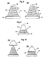
- FIG. 10 shows an embodiment of a valve in which the cover element 30 is placed on the upper area of the valve body 10. It remains, as can be seen better in the partial image (b), a flow gap 32 between cover 30 and valve body 10th
- the cover element 34 shown in Figure 11 is asymmetrical, here in that the pointing to the base 14 edge 36 of the cover member is not parallel to the base 14, but at a preselectable angle. This also corresponds to an asymmetry with respect to the longitudinal axis of the valve body which is perpendicular to the base 14.
- the spiral flow opening 22, which defines a pitch angle can be achieved here by a different angular position of the cover 34, so that the flow-through 22 is more or less closed in partial areas.
- manufacturing tolerances can be compensated. After the optimal position of the cover 34 is found, this is firmly connected to the valve body, for example by gluing or welding with mechanical locking.
- FIG. 12 shows a valve with a cover element 38, into which a seal is introduced, here in the form of a sealing ring 40, which faces the base 14 of the valve.
- the detail view “X” shows how the sealing ring 40 is attached to the cover 38.
Landscapes
- Engineering & Computer Science (AREA)
- General Engineering & Computer Science (AREA)
- Mechanical Engineering (AREA)
- Check Valves (AREA)
- Magnetically Actuated Valves (AREA)
- Electrically Driven Valve-Operating Means (AREA)
- Temperature-Responsive Valves (AREA)
- Valve Housings (AREA)
- Lift Valve (AREA)
Description
- Die Erfindung betrifft ein Ventil, das aus einer Offenstellung in eine Schließstellung und zurück bewegbar ist, mit einem Ventilkörper, dessen Basis an die Innenkontur einer Leitung angepaßt ist und der ein spiralig ausgebildetes Gewölbe aufweist.
- Die Anwendungsweise solcher Ventile ist offensichtlich. Besondere Probleme stellen sich, wenn beispielsweise große Rohrdurchmesser überbrückt werden müssen. Dann ergibt sich auch die Schwierigkeit, daß der Fließwiderstand so groß wird, daß ein definiertes Schließ- und Öffnungsverhalten des Ventils nicht mehr gewährleistet ist.
- Ein Ventil der eingangs genannten Gattung ist beispielsweise aus der
GB 15 970 A - Ein ähnliches Ventil ist in der
DE 500 753 C gezeigt, hier unter anderem mit einem kugelabschnittsartigen Gewölbe des Basiskörpers. Bei einigen Varianten ist ein stangenartiges Auslöseelement vorgesehen, welches, ähnlich wie bei derGB 15 970 A - Weitere Ventile der eingangs genannten Gattung sind in der
US 4 114 816 und in derFR 2 715 208 A - Es ist die Aufgabe der vorliegenden Erfindung, ein Ventil der obengenannten Gattung zur Verfügung zu stellen, mit dem große Rohrdurchmesser sicher geschlossen werden können.
- Diese Aufgabe wird durch ein Ventil nach Anspruch 1 gelöst. Vorteilhafte Ausgestaltungen sind Gegenstand der Unteransprüche.
- Erfindungsgemäß ist vorgesehen, der Querschnitt des Spiralenstranges des Ventilkörpers so gewählt ist, daß übereinanderliegende Gänge des Spiralenstranges in der Schließstellung ineinandergreifen. Das erfindungsgemäße Ventil arbeitet in effektiver Weise dadurch, daß sein Querschnitt gleichmäßig geöffnet oder geschlossen wird. Durch den spiralartigen Schnitt wird die Durchtrittsöffnung maximal, so daß ein geringer Fließwiderstand vorliegt. Durch die Stützwirkung der spiraligen aufeinanderliegenden Segmente sind große Durchmesser von Leitungen überbrückbar. Dieses Wirkprinzip ist mit einem Gewölbekeller vergleichbar. Über den Kegelwinkel bzw. die Steigung der Spirale ist das Anspringverhalten des Ventils einstellbar. Durch die Ausgestaltung des Profils des Spiralenstranges des Ventilkörpers kann der Strömungswiderstand und somit das Betriebsverhalten des Ventils eingestellt werden. Durch Auswahl des Profils kann die Stützwirkung der übereinanderliegenden Gänge des Spiralenstranges verbessert werden. In der Offenstellung wird dann die Durchströmöffnung entsprechend verändert, wobei durch die gewählte Ausformung, beispielsweise mit J-förmigem oder V-förmigem Querschnitt des Spiralenstranges der Strömungswiderstand erhöht wird. "Querschnitt des Spiralenstranges" bedeutet dabei die Schnittebene senkrecht zur Achse des augerollten Spiralenstranges, wie es im Zusammenhang mit Figur 7 veranschaulicht wird.
- Unter "Gewölbe" sollen domartige Strukturen verstanden werden. Nach einer ersten Ausgestaltung kann das Gewölbe ein kegelartiges Gewölbe sein, es ist aber ebenso vorteilhaft, wenn das Gewölbe ein kugelabschnittsartiges Gewölbe ist.
- Weiter vorteilhaft ist ein Auslöseelement vorgesehen, daß bevorzugt am Zenit des Gewölbes angebracht ist. Dieses Auslöseelement soll das Ventil in die Offenstellung bringen.
- Das Auslöseelement kann durch eine an ihm angebrachte Feder betätigbar sein. Mit separater Feder am Auslöseelement ist das Ventil als Gasstromwächter einsetzbar.
- Bevorzugt ist die Feder in der Symmetrieachse der Konkavität des Gewölbes angeordnet.
- Es liegt im Rahmen der Erfindung, daß der Ventilkörper selbst als Feder, welche die Auslösung direkt steuert, dient.
- Um das erfindungsgemäße Ventil als Wächter, insbesondere Gaswächter, nutzen zu können, muß es den entsprechenden Betriebsbedingungen, wie Druck, Fließgeschwindigkeit usw., angepaßt werden.
- Grundsätzlich kann durch den Einsatz unterschiedlicher Materialien bereits Einfluß auf die Steifigkeit genommen werden. So ist vorteilhaft das spiralig ausgebildete Gewölbe aus Metall oder aus Kunststoff, beispielsweise Polypropylen, Polyethylen, Polyamid oder dergleichen, hergestellt. Es ist möglich, dem Kunststoff Füllstoffe, wie Glasfaser, Ruß oder dergleichen, beizufügen, damit die gewünschten Federeigenschaften des Ventilkörpers erhalten werden.
- In einer Ausgestaltung der Erfindung ist der Querschnitt des Spiralenstranges über zumindest ein Teil seiner Länge konstant. Es kann aber auch gefordert sein, daß das Ventil über seine axiale Länge eine etwa gleichförmige Biegesteifigkeit aufweist. In diesem Fall kann vorgesehen werden, daß der Querschnitt des Spiralenstranges von der Basis zum Zenit des Gewölbes abnimmt. Die Dicke des Spiralenstranges wird daher bei abnehmendem Umfang des Ventilkörpers geringer.
- Auch kann vorgesehen sein, daß die im spiralig ausgebildeten Gewölbe in Offenstellung vorhandene Durchströmöffnung in der Offenstellung teilweise verschlossen bleibt oder verschließbar ist. Dies kann beispielsweise erreicht werden, indem bereits bei der Herstellung nur ein Abschnitt des Ventilkörpers spiralig geschnitten wird. Es kann aber auch vorgesehen sein, nachträglich ein Abdeckelement aufzubringen.
- Ein solches Abdeckelement kann mehr oder wenig eng am Ventilkörper anliegen und so für eine Erhöhung des Staudruckes sorgen. Damit kann der Strömungswiderstand eingestellt werden, was sich auf die Schließeigenschaften des Ventils auswirkt.
- Eine herstellungstechnische Vereinfachung ergibt sich, wenn das Abdeckelement bezüglich der Längsachse des Ventilkörpers asymmetrisch ausgebildet ist. Durch Drehen des Abdeckelementes können eventuelle Fertigungstoleranzen ausgeglichen bzw. Betriebsbereiche feinjustiert werden. Anschließend wird das asymmetrische Abdeckelement mit dem Ventilkörper verschweißt.
- Schließlich kann es sinnvoll sein, in das Abdeckelement eine Dichtung einzubringen. Damit kann das Abdeckelement auch als Abschlußkörper genutzt werden.
- Ein weiterer Vorteil der Verwendung von Abdeckelementen ist der Schutz vor Verunreinigungen.
- Im folgenden soll die Erfindung anhand der beigefügten Zeichnung näher erläutert werden. Es zeigt:
- Figur 1
- ein Ventil nach einer bevorzugten Ausführungsform der Erfindung im geöffneten Zustand;
- Figur 2
- eine perspektivische Ansicht des Ventils im geöffneten Zustand;
- Figur 3
- eine Ansicht des Ventils im geschlossenen Zustand;
- Figur 4
- eine perspektivische Ansicht des Ventils nach Figur 3;
- Figur 5
- die Anordnung eines Ventils gemäß der vorliegenden Erfindung in einem Rohr; und
- Figur 6
- das Ventil der Figur 5 in geöffnetem Zustand;
- Figur 7
- in den Teilbildern (a), (b) und (c) verschiedene Ausgestaltungen des Querschnittsprofils des Spiralenstrangs;
- Figur 8
- in Teilbildern (a) und (b) Ausführungsformen von Ventilen, mit denen die Einstellung der Biegesteifigkeit des Ventilkörpers veranschaulicht werden;
- Figur 9
- eine Ausführungsform des erfindungsgemäßen Ventils mit reduzierter Durchströmöffnung;
- Figur 10
- in Teilbildern (a) und (b) eine Ausführungsform eines Ventils mit Abdeckelement;
- Figur 11
- eine Ausführungsform des Ventils mit asymmetrischem Abdeckelement; und
- Figur 12
- eine Ausführungsform eines Ventils mit Abdeckelement, in das eine Dichtung eingebracht ist.
- Figur 1 zeigt eine Ausführungsform eines Ventils gemäß der vorliegenden Erfindung, in geöffnetem Zustand, bei dem ein Ventilkörper 10, der aus einem spiralig geschnittenen Gewölbe 12 mit integriert angebrachter Basis 14 im Öffnungszustand dargestellt. Das Gewölbe 12 ist bei der hier gezeigten Ausführungsform kegelartig, es ist aber auch eine halbkugelartige Ausgestaltung oder eine kugelabschnittsartige Ausgestaltung, eine pyramidenartige Ausgestaltung und dergleichen denkbar. Über den Kegelwinkel und/oder die Steigung der Spirale des Gewölbes 12 ist das Anspringverhalten des Ventils einstellbar. Somit kann das erfindungsgemäße Ventil, auch wenn es als Gasstromwächter eingesetzt wird, für den besonderen Einsatzfall optimiert werden. Andere Einstellmöglichkeiten werden weiter unten erläutert.
- Figur 2 zeigt das Ventil aus Figur 1 in perspektivischer Darstellung, wobei ersichtlich wird, daß der Querschnitt des Gewölbes 12 gleichmäßig geöffnet oder geschlossen werden kann. Dadurch wird die Betätigungskraft für das Ventil minimiert.
- Figur 3 zeigt das Ventil in geschlossenem Zustand. Die aufeinanderliegenden Gänge des Spiralenstranges 24 des Gewölbes 12 in Form eines Kegels bewirken, daß diese sich gegeneinander abstützen, ähnlich einer Bauart eines Gewölbekellers.
- Die perspektivische Ansicht der Figur 4 zeigt, wie im geschlossenen Zustand des Ventils die Spirale des Gewölbes 12 in sich geschlossen liegt und mit der Basis 14 für die Sperrung des Leitungsdurchmessers sorgt.
- In Figur 5 ist das erfindungsgemäße Ventil in seiner kegelartigen Ausgestaltung in Einbauzustand in einem Rohr 20 gezeigt. Schematisch angedeutet am Zenit 28 des Gewölbes 12 ist ein Auslöseelement 18, an dem beispielsweise ein Stellglied angreift. Wenn am Auslöseelement 18 eine separate Feder angreift, ist das Ventil als Gasstromwächter einsetzbar. Es muß gewährleistet sein, daß, wie in Figur 6 dargestellt ist, am Auslöseelement 18 eine Kraft F in der durch den Pfeil angezeigten Richtung angreift. Dabei ist es unerheblich, ob diese Kraft F durch eine oberhalb des Auslöseelementes 18 angebrachte Feder oder durch eine innerhalb des Kegels bzw. Gewölbes angeordnete Feder hervorgerufen wird. Wichtig ist lediglich, daß das spiralig geschnittene Gewölbe 12 so auseinandergezogen wird, daß die spiralige Durchtrittsöffnung 22 möglichst gleichmäßig aufgeweitet wird. Der Ventilkörper selbst kann in fenstellung hergestellt werden und wirkt je nach Material und Ausführung als Feder. Eine zusätzliche Feder ist somit bei einer solchen Ausgestaltung überflüssig.
- Figur 7 zeigt im Teilbild (a) in schematischer Weise drei übereinanderliegende Gänge des Spiralenstranges 24 eines Ventils, wobei bei dieser Ausgestaltung die Querschnittsfläche 26 des Spiralenstranges 24 rechteckig und über die axiale Länge des Ventilkörpers konstant ist. Der Fachmann erkennt, daß bei einer derartigen Ausgestaltung eine Verschiebung der Gänge des Spiralenstranges 24 gegeneinander möglich ist. In vielen Fällen ist dies nicht erwünscht. Daher kann es erfinderisch sein, wie im Teilbild (b) dargestellt, die Querschnittsfläche 26' unregelmäßig zu gestalten, beispielsweise in Form eines liegenden "J", so daß im geschlossenen Zustand des Ventils die Gänge des Spiralstranges 24 ineinandergreifen. In geöffnetem Zustand des Ventils muß das Medium einen Richtungswechsel in der Durchströmöffnung 22 vornehmen, so daß es hier zu einer Erhöhung des Strömungswiderstandes kommt. Eine weitere Ausgestaltung zeigt das Teilbild (c) mit einem Spiralenstrang 24, einen Querschnitt 26" der in Forme eines auf dem Kopf stehenden "V" gestaltet ist.
- Figur 8 zeigt im Teilbild (a) eine Ausgestaltung des Ventils, bei der, beginnend bei der Basis 14, der Spiralenstrang 24 bis zum Zenit 28 einen konstanten Querschnitt aufweist, was in dieser Darstellung durch eine ebenso konstante Dicke d des Spiralenstranges 24 veranschaulicht wird. Wenn nun das Ventil bzw. genauer der Ventilkörper 10 über seine axiale Länge eine etwa konstante Biegesteifigkeit aufweisen soll, kann dies dadurch erreicht werden, daß, wie in Teilbild (b) dargestellt, der Spiralenstrang 24 an der Basis 14 eine größere Dicke d1 aufweist als in der Nähe des Zenits 28, wobei die Dicke d1 bei der hier dargestellten Ausführungsform kontinuierlich auf die Dicke d2 abnimmt. Die geringe Dicke gleicht damit den geringeren Umfang des Ventilkörpers 10 und damit die geringere wirksame Fläche aus.
- Figur 9 zeigt eine Ausführungsform eines Ventils, bei dem der Ventilkörper 10 nur teilweise, nämlich in der Nähe der Basis 14, spiralig ausgebildet ist. Herstellungstechnisch kann dies erfolgen, indem beispielsweise aus dem Gewölbe 12 nur wenige Gänge des Spiralenstranges 24 ausgeschnitten werden. Der obere Bereich des Gewölbes 12 bleibt geschlossen. Der Spiralenstrang 24 kann in anderen Abschnitten des Gewölbes 12 ausgebildet sein, so daß es beispielsweise auch denkbar wäre, in der Nähe der Basis 4 das Gewölbe 12 geschlossen zu halten, während der Spiralenstrang 24 unterhalb des Zenites 28 geschnitten wird.
- Dieselbe Wirkung wird mit einem nachträglich aufgebrachten Abdeckelement erreicht.
- Figur 10 zeigt eine Ausführungsform eines Ventils, bei dem das Abdeckelement 30 auf den oberen Bereich des Ventilkörpers 10 aufgesetzt wird. Dabei verbleibt, wie besser im Teilbild (b) zu erkennen ist, ein Strömungsspalt 32 zwischen Abdeckelement 30 und Ventilkörper 10.
- Das in Figur 11 dargestellte Abdeckelement 34 ist asymmetrisch ausgebildet, hier dadurch, daß die zur Basis 14 weisende Kante 36 des Abdeckelementes nicht parallel zur Basis 14 verläuft, sondern unter einem vorwählbaren Winkel. Dies entspricht auch einer Asymmetrie in bezug auf die Längsachse des Ventilkörpers, die senkrecht zur Basis 14 verläuft. Im Zusammenwirken mit der spiraligen Durchströmöffnung 22, die einen Steigungswinkel definiert, kann hier durch eine unterschiedliche Winkelstellung des Abdeckelementes 34 erreicht werden, so daß die Durchströmöffnung 22 in Teilbereichen mehr oder weniger verschlossen wird. Damit ist eine Feinjustierung der Betriebseigenschaften des Ventils möglich, auch können Fertigungstoleranzen ausgeglichen werden. Nachdem die optimale Position des Abdeckelementes 34 gefunden ist, wird dieses fest mit dem Ventilkörper verbunden, beispielsweise durch Verkleben oder Verschweißen bei mechanischer Verriegelung.
- Figur 12 zeigt ein Ventil mit einem Abdeckelement 38, in das eine Dichtung eingebracht ist, hier in Form eines Dichtringes 40, welche zur Basis 14 des Ventils weist. Die Detailansicht "X" zeigt, wie der Dichtring 40 an das Abdeckelement 38 angesetzt ist.
- Es soll verstanden werden, daß, obwohl die Erfindung mit Bezug auf ein kegelartiges Ventil beschrieben worden ist, auch andere gewölbeartige Ausgestaltungen von Ventilen bzw. deren Ventilkörpern umfaßt sind. Insbesondere können auch andere als kreisförmige Querschnitte, beispielsweise ovale, überbrückbar sein.
- Die in der vorstehenden Beschreibung, in der Zeichnung sowie in den Ansprüchen offenbarten Merkmale der Erfindung können sowohl einzeln als auch in beliebiger Kombination für die Verwirklichung der Erfindung wesentlich sein.
Claims (15)
- Ventil, das aus einer Offenstellung in eine Schließstellung und zurück bewegbar ist, mit einem Ventilkörper (10), dessen Basis (14) an die Innenkontur einer Leitung angepaßt ist und der ein spiralig ausgebildetes Gewölbe aufweist, dadurch gekennzeichnet, daß der Querschnitt (26', 26") des Spiralenstranges (24) des Ventilkörpers (10) so gewählt ist, daß übereinanderliegende Gänge des Spiralenstranges (24) in der Schließstellung des Ventils ineinandergreifen.
- Ventil nach Anspruch 1, dadurch gekennzeichnet, daß das Gewölbe (12) ein kegelartiges Gewölbe ist.
- Ventil nach Anspruch 1, dadurch gekennzeichnet, daß das Gewölbe (12) ein kugelabschnittsartiges Gewölbe ist.
- Ventil nach einem der Anspruch 1 bis 3, dadurch gekennzeichnet, daß am Zenit des Gewölbes (12) ein Auslöseelement (18) angebracht ist, welches das Ventil in die Offenstellung bzw. Schließstellung bringt.
- Ventil nach Anspruch 4, dadurch gekennzeichnet, daß das Auslöseelement (18) durch eine an ihm angebrachte Feder betätigbar ist.
- Ventil nach Anspruch 4, dadurch gekennzeichnet, daß der Ventilkörper die Feder darstellt.
- Ventil nach Anspruch 5, dadurch gekennzeichnet, daß die Feder in der Symmetrieachse der Konkavität des Gewölbes (12) angeordnet ist.
- Ventil nach einem der Ansprüche 1 bis 7, dadurch gekennzeichnet, daß das spiralig ausgebildete Gewölbe (12) aus Metall oder Kunststoff, beispielsweise Polypropylen, Polyethylen, Polyamid oder dergleichen, hergestellt ist.
- Ventil nach Anspruch 8, dadurch gekennzeichnet, daß der Kunststoff Füllstoffe, wie Glasfaser, Ruß oder dergleichen, enthält.
- Ventil nach Anspruch 1, dadurch gekennzeichnet, daß der Querschnitt (26, 26', 26") des Spiralenstranges (24) über zumindest einen Teil seiner Länge konstant ist.
- Ventil nach Anspruch 1, dadurch gekennzeichnet, daß der Querschnitt des Spiralenstranges (24) von der Basis (14) zum Zenit (28) des Gewölbes (12) abnimmt.
- Ventil nach Anspruch 1, dadurch gekennzeichnet, daß die im spiralig ausgebildeten Gewölbe (1) in Offenstellung vorhandene Durchströmöffnung (22) in der Offenstellung des Ventils teilweise verschlossen bleibt oder verschließbar ist.
- Ventil nach einem der vorangehenden Ansprüche, dadurch gekennzeichnet, daß zumindest ein Teil des spiralig ausgebildeten Gewölbes (12) mit einem Abdeckelement (30, 34, 38) versehen ist.
- Ventil nach Anspruch 13, dadurch gekennzeichnet, daß das Abdeckelement (34) bezüglich des Längsachse des Ventilkörpers (10) asymmetrisch ausgebildet ist.
- Ventil nach Anspruch 13, dadurch gekennzeichnet, daß in das Abdeckelement (38) eine Dichtung (40) eingebracht ist.
Applications Claiming Priority (1)
| Application Number | Priority Date | Filing Date | Title |
|---|---|---|---|
| DE102004032584 | 2004-07-05 |
Publications (3)
| Publication Number | Publication Date |
|---|---|
| EP1614948A2 EP1614948A2 (de) | 2006-01-11 |
| EP1614948A3 EP1614948A3 (de) | 2006-02-01 |
| EP1614948B1 true EP1614948B1 (de) | 2007-08-29 |
Family
ID=35045212
Family Applications (1)
| Application Number | Title | Priority Date | Filing Date |
|---|---|---|---|
| EP05014519A Expired - Lifetime EP1614948B1 (de) | 2004-07-05 | 2005-07-05 | Ventil |
Country Status (4)
| Country | Link |
|---|---|
| EP (1) | EP1614948B1 (de) |
| AT (1) | ATE371830T1 (de) |
| DE (1) | DE502005001355D1 (de) |
| ES (1) | ES2293433T3 (de) |
Cited By (1)
| Publication number | Priority date | Publication date | Assignee | Title |
|---|---|---|---|---|
| WO2025029211A1 (en) * | 2023-07-31 | 2025-02-06 | Noztech Petrol Eki̇pmanlari Teknoloji̇ Sanayi̇ Ti̇caret Anoni̇m Şi̇rketi̇ | A fluid filling nozzle with a drip stop element |
Family Cites Families (4)
| Publication number | Priority date | Publication date | Assignee | Title |
|---|---|---|---|---|
| GB191415970A (en) * | 1913-07-08 | 1900-01-01 | L Oxylithe | An Improved Distributing Member for Liquids, Gases or Vapours applicable to Distributing Apparatus of every description. |
| DE500753C (de) * | 1927-04-02 | 1930-06-28 | Adolf Watzinger Dr Ing | Ventil aus schraubenfoermig gewickeltem, elastischem Rundmaterial |
| US4114816A (en) * | 1976-03-29 | 1978-09-19 | Schold George R | Apparatus for dispersing finely divided solid particles in a liquid vehicle |
| FR2715208B1 (fr) * | 1994-01-18 | 1996-05-24 | Eric Vincent | Clapet ressort pour fluide. |
-
2005
- 2005-07-05 DE DE502005001355T patent/DE502005001355D1/de not_active Expired - Lifetime
- 2005-07-05 ES ES05014519T patent/ES2293433T3/es not_active Expired - Lifetime
- 2005-07-05 AT AT05014519T patent/ATE371830T1/de not_active IP Right Cessation
- 2005-07-05 EP EP05014519A patent/EP1614948B1/de not_active Expired - Lifetime
Non-Patent Citations (1)
| Title |
|---|
| None * |
Cited By (1)
| Publication number | Priority date | Publication date | Assignee | Title |
|---|---|---|---|---|
| WO2025029211A1 (en) * | 2023-07-31 | 2025-02-06 | Noztech Petrol Eki̇pmanlari Teknoloji̇ Sanayi̇ Ti̇caret Anoni̇m Şi̇rketi̇ | A fluid filling nozzle with a drip stop element |
Also Published As
| Publication number | Publication date |
|---|---|
| EP1614948A2 (de) | 2006-01-11 |
| DE502005001355D1 (de) | 2007-10-11 |
| ATE371830T1 (de) | 2007-09-15 |
| ES2293433T3 (es) | 2008-03-16 |
| EP1614948A3 (de) | 2006-02-01 |
Similar Documents
| Publication | Publication Date | Title |
|---|---|---|
| EP2873894B1 (de) | Verschlussstopfen | |
| DE60310346T2 (de) | Verschlussstopfen für eine Öffnung in einem Bauteil | |
| DE2241273C2 (de) | Biegsame Dichtung aus Metall | |
| EP2477717B1 (de) | Filter für flüssige oder gasförmige medien | |
| DE20310390U1 (de) | Anschlussdichtung mit Ratschenzähnen | |
| EP1516237B1 (de) | Durchflussmengenregler | |
| DE102016116550B4 (de) | Drehschieberventil mit kompaktem Dichtelement | |
| EP1593898A1 (de) | Dichtelement | |
| EP1564473B1 (de) | Steckfitting mit einem Klemmring | |
| EP1893903A1 (de) | Pressfitting für ein rohr | |
| AT505646B1 (de) | Rohrverbindung mit einem gehäuse einer armatur | |
| DE10207104A1 (de) | Kegelstumpfförmiges Dichtungsanschlussstück | |
| DE3042818A1 (de) | Kugelventil | |
| EP3204561B1 (de) | Füllventil | |
| WO2004083698A1 (de) | Einbauteil zum einsetzen in eine gas- oder flüssigkeitsleitung | |
| EP1614948B1 (de) | Ventil | |
| EP4025812B1 (de) | Metallische abdichtung für ein klappenventil | |
| EP1058033B1 (de) | Nocken für zusammensgesetzte Nockenwelle | |
| DE3505196A1 (de) | Waermetauscher, insbesondere fuer kraftfahrzeuge | |
| DE20103010U1 (de) | Dichtungsvorrichtung, insbesondere zum innenseitigen Abdichten von Rohrleitungen und/oder Gebäudeöffnungen | |
| WO2009071501A1 (de) | ROHR MIT EINER DURCH EIN OBERFLÄCHENPROFIL MODIFIZIERTEN AUßENMANTELFLÄCHE | |
| DE19647257C2 (de) | Manschette zum Abdichten einer Wanddurchbrechung | |
| EP0694143A1 (de) | Rohrleitungsverbindung, rohrleitungsverbinder und hydraulikvorrichtung zur herstellung von rohrleitungsverbindungen | |
| DE9408546U1 (de) | Stützdom für einen Fluidfilter | |
| DE10134831C1 (de) | Verschlusseinrichtung für eine rohrförmige Leitung zur Förderung eines gasförmigen oder flüssigen Mediums |
Legal Events
| Date | Code | Title | Description |
|---|---|---|---|
| PUAI | Public reference made under article 153(3) epc to a published international application that has entered the european phase |
Free format text: ORIGINAL CODE: 0009012 |
|
| PUAL | Search report despatched |
Free format text: ORIGINAL CODE: 0009013 |
|
| AK | Designated contracting states |
Kind code of ref document: A2 Designated state(s): AT BE BG CH CY CZ DE DK EE ES FI FR GB GR HU IE IS IT LI LT LU LV MC NL PL PT RO SE SI SK TR |
|
| AX | Request for extension of the european patent |
Extension state: AL BA HR MK YU |
|
| AK | Designated contracting states |
Kind code of ref document: A3 Designated state(s): AT BE BG CH CY CZ DE DK EE ES FI FR GB GR HU IE IS IT LI LT LU LV MC NL PL PT RO SE SI SK TR |
|
| AX | Request for extension of the european patent |
Extension state: AL BA HR MK YU |
|
| 17P | Request for examination filed |
Effective date: 20060731 |
|
| AKX | Designation fees paid |
Designated state(s): AT BE BG CH CY CZ DE DK EE ES FI FR GB GR HU IE IS IT LI LT LU LV MC NL PL PT RO SE SI SK TR |
|
| 17Q | First examination report despatched |
Effective date: 20060913 |
|
| GRAP | Despatch of communication of intention to grant a patent |
Free format text: ORIGINAL CODE: EPIDOSNIGR1 |
|
| GRAS | Grant fee paid |
Free format text: ORIGINAL CODE: EPIDOSNIGR3 |
|
| GRAA | (expected) grant |
Free format text: ORIGINAL CODE: 0009210 |
|
| AK | Designated contracting states |
Kind code of ref document: B1 Designated state(s): AT BE BG CH CY CZ DE DK EE ES FI FR GB GR HU IE IS IT LI LT LU LV MC NL PL PT RO SE SI SK TR |
|
| REG | Reference to a national code |
Ref country code: GB Ref legal event code: FG4D Free format text: NOT ENGLISH |
|
| REG | Reference to a national code |
Ref country code: CH Ref legal event code: EP |
|
| REG | Reference to a national code |
Ref country code: IE Ref legal event code: FG4D Free format text: LANGUAGE OF EP DOCUMENT: GERMAN |
|
| REF | Corresponds to: |
Ref document number: 502005001355 Country of ref document: DE Date of ref document: 20071011 Kind code of ref document: P |
|
| REG | Reference to a national code |
Ref country code: CH Ref legal event code: NV Representative=s name: BUECHEL, KAMINSKI & PARTNER PATENTANWAELTE ESTABLI |
|
| GBT | Gb: translation of ep patent filed (gb section 77(6)(a)/1977) |
Effective date: 20071205 |
|
| PG25 | Lapsed in a contracting state [announced via postgrant information from national office to epo] |
Ref country code: IS Free format text: LAPSE BECAUSE OF FAILURE TO SUBMIT A TRANSLATION OF THE DESCRIPTION OR TO PAY THE FEE WITHIN THE PRESCRIBED TIME-LIMIT Effective date: 20071229 Ref country code: FI Free format text: LAPSE BECAUSE OF FAILURE TO SUBMIT A TRANSLATION OF THE DESCRIPTION OR TO PAY THE FEE WITHIN THE PRESCRIBED TIME-LIMIT Effective date: 20070829 Ref country code: LT Free format text: LAPSE BECAUSE OF FAILURE TO SUBMIT A TRANSLATION OF THE DESCRIPTION OR TO PAY THE FEE WITHIN THE PRESCRIBED TIME-LIMIT Effective date: 20070829 |
|
| PG25 | Lapsed in a contracting state [announced via postgrant information from national office to epo] |
Ref country code: PL Free format text: LAPSE BECAUSE OF FAILURE TO SUBMIT A TRANSLATION OF THE DESCRIPTION OR TO PAY THE FEE WITHIN THE PRESCRIBED TIME-LIMIT Effective date: 20070829 |
|
| REG | Reference to a national code |
Ref country code: ES Ref legal event code: FG2A Ref document number: 2293433 Country of ref document: ES Kind code of ref document: T3 |
|
| PG25 | Lapsed in a contracting state [announced via postgrant information from national office to epo] |
Ref country code: LV Free format text: LAPSE BECAUSE OF FAILURE TO SUBMIT A TRANSLATION OF THE DESCRIPTION OR TO PAY THE FEE WITHIN THE PRESCRIBED TIME-LIMIT Effective date: 20070829 |
|
| REG | Reference to a national code |
Ref country code: IE Ref legal event code: FD4D |
|
| ET | Fr: translation filed | ||
| PG25 | Lapsed in a contracting state [announced via postgrant information from national office to epo] |
Ref country code: GR Free format text: LAPSE BECAUSE OF FAILURE TO SUBMIT A TRANSLATION OF THE DESCRIPTION OR TO PAY THE FEE WITHIN THE PRESCRIBED TIME-LIMIT Effective date: 20071130 Ref country code: DK Free format text: LAPSE BECAUSE OF FAILURE TO SUBMIT A TRANSLATION OF THE DESCRIPTION OR TO PAY THE FEE WITHIN THE PRESCRIBED TIME-LIMIT Effective date: 20070829 |
|
| PG25 | Lapsed in a contracting state [announced via postgrant information from national office to epo] |
Ref country code: PT Free format text: LAPSE BECAUSE OF FAILURE TO SUBMIT A TRANSLATION OF THE DESCRIPTION OR TO PAY THE FEE WITHIN THE PRESCRIBED TIME-LIMIT Effective date: 20080129 Ref country code: SK Free format text: LAPSE BECAUSE OF FAILURE TO SUBMIT A TRANSLATION OF THE DESCRIPTION OR TO PAY THE FEE WITHIN THE PRESCRIBED TIME-LIMIT Effective date: 20070829 Ref country code: CZ Free format text: LAPSE BECAUSE OF FAILURE TO SUBMIT A TRANSLATION OF THE DESCRIPTION OR TO PAY THE FEE WITHIN THE PRESCRIBED TIME-LIMIT Effective date: 20070829 Ref country code: IE Free format text: LAPSE BECAUSE OF FAILURE TO SUBMIT A TRANSLATION OF THE DESCRIPTION OR TO PAY THE FEE WITHIN THE PRESCRIBED TIME-LIMIT Effective date: 20070829 |
|
| PG25 | Lapsed in a contracting state [announced via postgrant information from national office to epo] |
Ref country code: RO Free format text: LAPSE BECAUSE OF FAILURE TO SUBMIT A TRANSLATION OF THE DESCRIPTION OR TO PAY THE FEE WITHIN THE PRESCRIBED TIME-LIMIT Effective date: 20070829 Ref country code: SE Free format text: LAPSE BECAUSE OF FAILURE TO SUBMIT A TRANSLATION OF THE DESCRIPTION OR TO PAY THE FEE WITHIN THE PRESCRIBED TIME-LIMIT Effective date: 20071129 |
|
| PLBE | No opposition filed within time limit |
Free format text: ORIGINAL CODE: 0009261 |
|
| STAA | Information on the status of an ep patent application or granted ep patent |
Free format text: STATUS: NO OPPOSITION FILED WITHIN TIME LIMIT |
|
| 26N | No opposition filed |
Effective date: 20080530 |
|
| PGFP | Annual fee paid to national office [announced via postgrant information from national office to epo] |
Ref country code: TR Payment date: 20080611 Year of fee payment: 4 |
|
| PGFP | Annual fee paid to national office [announced via postgrant information from national office to epo] |
Ref country code: ES Payment date: 20080821 Year of fee payment: 4 |
|
| PGFP | Annual fee paid to national office [announced via postgrant information from national office to epo] |
Ref country code: AT Payment date: 20080711 Year of fee payment: 4 Ref country code: FR Payment date: 20080718 Year of fee payment: 4 Ref country code: NL Payment date: 20080703 Year of fee payment: 4 |
|
| PG25 | Lapsed in a contracting state [announced via postgrant information from national office to epo] |
Ref country code: MC Free format text: LAPSE BECAUSE OF NON-PAYMENT OF DUE FEES Effective date: 20080731 |
|
| PG25 | Lapsed in a contracting state [announced via postgrant information from national office to epo] |
Ref country code: EE Free format text: LAPSE BECAUSE OF FAILURE TO SUBMIT A TRANSLATION OF THE DESCRIPTION OR TO PAY THE FEE WITHIN THE PRESCRIBED TIME-LIMIT Effective date: 20070829 |
|
| PG25 | Lapsed in a contracting state [announced via postgrant information from national office to epo] |
Ref country code: SI Free format text: LAPSE BECAUSE OF FAILURE TO SUBMIT A TRANSLATION OF THE DESCRIPTION OR TO PAY THE FEE WITHIN THE PRESCRIBED TIME-LIMIT Effective date: 20070829 |
|
| PG25 | Lapsed in a contracting state [announced via postgrant information from national office to epo] |
Ref country code: CY Free format text: LAPSE BECAUSE OF FAILURE TO SUBMIT A TRANSLATION OF THE DESCRIPTION OR TO PAY THE FEE WITHIN THE PRESCRIBED TIME-LIMIT Effective date: 20070829 |
|
| PGFP | Annual fee paid to national office [announced via postgrant information from national office to epo] |
Ref country code: BE Payment date: 20090126 Year of fee payment: 4 |
|
| PG25 | Lapsed in a contracting state [announced via postgrant information from national office to epo] |
Ref country code: BG Free format text: LAPSE BECAUSE OF FAILURE TO SUBMIT A TRANSLATION OF THE DESCRIPTION OR TO PAY THE FEE WITHIN THE PRESCRIBED TIME-LIMIT Effective date: 20071129 |
|
| REG | Reference to a national code |
Ref country code: CH Ref legal event code: PFA Owner name: FRIATEC AKTIENGESELLSCHAFT Free format text: FRIATEC AKTIENGESELLSCHAFT#STEINZEUGSTRASSE 50#68229 MANNHEIM (DE) -TRANSFER TO- FRIATEC AKTIENGESELLSCHAFT#STEINZEUGSTRASSE 50#68229 MANNHEIM (DE) |
|
| BERE | Be: lapsed |
Owner name: FRIATEC A.G. Effective date: 20090731 |
|
| REG | Reference to a national code |
Ref country code: CH Ref legal event code: PL |
|
| GBPC | Gb: european patent ceased through non-payment of renewal fee |
Effective date: 20090705 |
|
| NLV4 | Nl: lapsed or anulled due to non-payment of the annual fee |
Effective date: 20100201 |
|
| REG | Reference to a national code |
Ref country code: FR Ref legal event code: ST Effective date: 20100331 |
|
| PG25 | Lapsed in a contracting state [announced via postgrant information from national office to epo] |
Ref country code: CH Free format text: LAPSE BECAUSE OF NON-PAYMENT OF DUE FEES Effective date: 20090731 Ref country code: FR Free format text: LAPSE BECAUSE OF NON-PAYMENT OF DUE FEES Effective date: 20090731 Ref country code: LI Free format text: LAPSE BECAUSE OF NON-PAYMENT OF DUE FEES Effective date: 20090731 |
|
| PG25 | Lapsed in a contracting state [announced via postgrant information from national office to epo] |
Ref country code: GB Free format text: LAPSE BECAUSE OF NON-PAYMENT OF DUE FEES Effective date: 20090705 |
|
| PG25 | Lapsed in a contracting state [announced via postgrant information from national office to epo] |
Ref country code: BE Free format text: LAPSE BECAUSE OF NON-PAYMENT OF DUE FEES Effective date: 20090731 Ref country code: AT Free format text: LAPSE BECAUSE OF NON-PAYMENT OF DUE FEES Effective date: 20090705 |
|
| PG25 | Lapsed in a contracting state [announced via postgrant information from national office to epo] |
Ref country code: LU Free format text: LAPSE BECAUSE OF NON-PAYMENT OF DUE FEES Effective date: 20080705 Ref country code: HU Free format text: LAPSE BECAUSE OF FAILURE TO SUBMIT A TRANSLATION OF THE DESCRIPTION OR TO PAY THE FEE WITHIN THE PRESCRIBED TIME-LIMIT Effective date: 20080301 |
|
| REG | Reference to a national code |
Ref country code: ES Ref legal event code: FD2A Effective date: 20090706 |
|
| PG25 | Lapsed in a contracting state [announced via postgrant information from national office to epo] |
Ref country code: ES Free format text: LAPSE BECAUSE OF NON-PAYMENT OF DUE FEES Effective date: 20090706 |
|
| PGFP | Annual fee paid to national office [announced via postgrant information from national office to epo] |
Ref country code: IT Payment date: 20080731 Year of fee payment: 4 |
|
| PG25 | Lapsed in a contracting state [announced via postgrant information from national office to epo] |
Ref country code: NL Free format text: LAPSE BECAUSE OF NON-PAYMENT OF DUE FEES Effective date: 20100201 |
|
| PG25 | Lapsed in a contracting state [announced via postgrant information from national office to epo] |
Ref country code: TR Free format text: LAPSE BECAUSE OF NON-PAYMENT OF DUE FEES Effective date: 20090705 |
|
| PGFP | Annual fee paid to national office [announced via postgrant information from national office to epo] |
Ref country code: DE Payment date: 20130729 Year of fee payment: 9 |
|
| REG | Reference to a national code |
Ref country code: DE Ref legal event code: R119 Ref document number: 502005001355 Country of ref document: DE |
|
| PG25 | Lapsed in a contracting state [announced via postgrant information from national office to epo] |
Ref country code: DE Free format text: LAPSE BECAUSE OF NON-PAYMENT OF DUE FEES Effective date: 20150203 |
|
| REG | Reference to a national code |
Ref country code: DE Ref legal event code: R119 Ref document number: 502005001355 Country of ref document: DE Effective date: 20150203 |